
You also want an ePaper? Increase the reach of your titles
YUMPU automatically turns print PDFs into web optimized ePapers that Google loves.
HEAVY-DUTY MILL/<strong>drill</strong><br />
MODEL G1006/G1007<br />
Owner's Manual<br />
Copyright © 2000 By Grizzly Industrial, Inc. Revised August, 2008 (JB)<br />
Warning: No portion of this manual may be reproduced in any shape<br />
or form without the written approval of Grizzly Industrial, inc.<br />
#JB10548 printed in China
Table of Contents<br />
SECTION 1: INTRODUCTION.......................... 2<br />
Foreword........................................................ 2<br />
Contact Info.................................................... 2<br />
Functional Overview....................................... 2<br />
Identification................................................... 3<br />
SECTION 1: SAFETY........................................ 9<br />
Safety Instructions for Machinery................... 9<br />
Additional Safety for Mills............................. 11<br />
SECTION 2: CIRCUIT REQUIREMENTS....... 12<br />
110/220V Operation..................................... 12<br />
SECTION 3: SETUP........................................ 13<br />
Setup Safety................................................. 13<br />
Items Needed for Setup............................... 13<br />
Unpacking..................................................... 13<br />
Inventory....................................................... 13<br />
Clean Up...................................................... 14<br />
Site Considerations...................................... 15<br />
Moving & Placing Machine........................... 15<br />
Mounting....................................................... 16<br />
Assembly...................................................... 16<br />
Power Feed (G1007 Only)........................... 17<br />
Head Crank.................................................. 19<br />
Feed Levers................................................. 20<br />
Collet/Arbor................................................... 20<br />
Drill Chuck/Arbor.......................................... 21<br />
Fly Cutter/Arbor............................................ 22<br />
Test Run....................................................... 22<br />
SECTION 4: OPERATIONS............................ 23<br />
Operation Safety.......................................... 23<br />
Graduated Dials........................................... 23<br />
Spindle Height.............................................. 24<br />
Depth Stop................................................... 25<br />
Head Height................................................. 25<br />
Speed Changes............................................ 26<br />
SECTION 5: ACCESSORIES.......................... 27<br />
SECTION 6: MAINTENANCE......................... 29<br />
Schedule....................................................... 29<br />
Cleaning and Protecting............................... 29<br />
Lubrication.................................................... 30<br />
Table Leadscrews........................................ 32<br />
SECTION 7: SERVICE.................................... 33<br />
Troubleshooting............................................ 33<br />
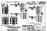
Wiring Diagram............................................. 36<br />
Head Parts Breakdown............................... 37<br />
Head Parts List............................................. 38<br />
Column & Table Parts Breakdown............... 39<br />
Column & Table Parts List........................... 40<br />
Warning Labels Breakdown and List............ 41<br />
WARRANTY AND RETURNS......................... 44
SECTION 1: INTRODUCTION<br />
Foreword<br />
Functional Overview<br />
We are proud to offer the Model G1006/7 Mill/Drill.<br />
This machine is part of a growing Grizzly family of<br />
fine metalworking machinery. When used according<br />
to the guidelines set forth in this manual,<br />
you can expect years of trouble-free, enjoyable<br />
operation and proof of Grizzly’s commitment to<br />
customer satisfaction.<br />
The specifications, drawings, and photographs<br />
illustrated in this manual represent the Model<br />
G1006/7 when the manual was prepared.<br />
However, owing to Grizzly’s policy of continuous<br />
improvement, changes may be made at any time<br />
with no obligation on the part of Grizzly. For your<br />
convenience, we always keep current Grizzly<br />
manuals available on our website at www.grizzly.com.<br />
Any updates to your machine will be<br />
reflected in these manuals as soon as they are<br />
complete. Visit our site often to check for the latest<br />
updates to this manual!<br />
Contact Info<br />
We stand behind our machines. If you have any<br />
service questions, parts requests or general<br />
questions about the machine, please call or write<br />
us at the location listed below.<br />
Grizzly Industrial, Inc.<br />
1203 Lycoming Mall Circle<br />
Muncy, PA 17756<br />
Phone: (570) 546-9663<br />
Fax: (800) 438-5901<br />
E-Mail: techsupport@grizzly.com<br />
The Model G1006/G1007 Mill/Drill is used to<br />
remove material from metal workpieces to form<br />
complex shapes. It can also be used as a traditional<br />
<strong>drill</strong> press.<br />
Tooling attaches to the spindle that, in turn,<br />
attaches to the vertically moveable quill. The quill<br />
position is controlled by the downfeed handles and<br />
the fine micro-downfeed handwheel. The spindle<br />
is driven by the adjustable belt system contained<br />
within the head of the <strong>mill</strong>. The head itself can be<br />
moved across the table in a horizontal arc.<br />
Generally, the tooling rotates in a stationary position<br />
while the table and workpiece move into the<br />
cutter in one of two paths—longitudinal (X-axis)<br />
and cross (Y-axis). Some operations, however,<br />
such as <strong>drill</strong>ing or tapping, are better accomplished<br />
using vertical quill movement.<br />
The Model G1007 includes a powerfeed that provides<br />
powered movement along the X-axis.<br />
To perform <strong>mill</strong>ing tasks, the workpiece positioned<br />
and clamped to the table so that the movement<br />
of the table will bring the workpiece across the<br />
cutting tool to produce the desired cut. The depth<br />
of the quill is adjusted, as are any needed travel<br />
stops. The machine is turned ON and the table is<br />
moved either manually or by the power feed past<br />
the spinning cutting tool.<br />
Once the pass is complete, adjustments may be<br />
made to the position of the quill and the table, and<br />
further passes follow, as necessary.<br />
If you have any comments regarding this manual,<br />
please write to us at the address below:<br />
Grizzly Industrial, Inc.<br />
C<br />
/O Technical Documentation Manager<br />
P.O. Box 2069<br />
Bellingham, WA 98227-2069<br />
Email: manuals@grizzly.com<br />
-2- G1006/7 Heavy Duty Mill/Drill
Identification<br />
C<br />
D<br />
B<br />
A<br />
E<br />
H<br />
I<br />
F<br />
G<br />
J<br />
K<br />
P<br />
Q<br />
O<br />
N<br />
M<br />
L<br />
Figure 1. Identification.<br />
A. Junction Box<br />
B. Headstock Height Crank<br />
C. Return Spring Assembly<br />
D. Quill Lock<br />
E. ON/OFF Swtich<br />
F. Depth Stop<br />
G. Micro-Downfeed Handwheel<br />
H. Motor Pivot Lock<br />
I. Downfeed Handles<br />
J. Pinion Hub Lock Knob<br />
K. X-Axis Handwheels<br />
L. Longitudinal Stops<br />
M. Gib Screws<br />
N. Longitudinal Locks<br />
O. Y-Axis Handwheel<br />
P. Drilling Angle Vise<br />
Q. Power Feed (G1007 Only)<br />
G1006/7 Heavy Duty Mill/Drill -3-
MACHINE DATA<br />
SHEET<br />
Customer service #: (570) 546-9663 · to order Call: (800) 523-4777 · Fax #: (800) 438-5901<br />
Product Dimensions:<br />
MODEL G1006 2 HP MILL/DRILL<br />
Weight.............................................................................................................................................................. 566 lbs.<br />
length/Width/height....................................................................................................................... 50 x 40 x 48-1/2 in.<br />
Foot print (length/Width)............................................................................................................................. 24 x 16 in.<br />
Shipping Dimensions:<br />
Electrical:<br />
Motors:<br />
type........................................................................................................................................................... Wood Crate<br />
Content............................................................................................................................................................ Machine<br />
Weight.............................................................................................................................................................. 674 lbs.<br />
length/Width/height............................................................................................................................. 38 x 30 x 46 in.<br />
switch..................................................................................................push Button with thermal overload protection<br />
switch voltage...................................................................................................................................................... 110v<br />
Cord length............................................................................................................................................................ 6 ft.<br />
Cord gauge....................................................................................................................................................14 gauge<br />
recommended Breaker size................................................................................20 amps at 110v, 15 amps at 220v<br />
plug.........................................................................................................................................................................yes<br />
Main<br />
type.................................................................................................................. teFC Capacitor start induction<br />
horsepower.................................................................................................................................................2 hp<br />
voltage.................................................................................................................................................110/220v<br />
prewired......................................................................................................................................................110v<br />
phase........................................................................................................................................................ single<br />
amps..........................................................................................................................................................18/9a<br />
speed.................................................................................................................................................1725 rpM<br />
Cycle..........................................................................................................................................................60 hz<br />
number of speeds........................................................................................................................................... 1<br />
power transfer ................................................................................................................................... Belt drive<br />
Bearings........................................................................................................ shielded, permanently lubricated<br />
Main Specifications:<br />
Model G1006<br />
Operation Info<br />
spindle travel.............................................................................................................................................. 5 in.<br />
swing................................................................................................................................................... 15-7/8 in.<br />
longitudinal table travel.....................................................................................................................23-1/2 in.<br />
Cross table travel....................................................................................................................................... 7 in.<br />
ram travel.................................................................................................................................................12 in.<br />
head travel............................................................................................................................................5-1/4 in.<br />
head swivel.......................................................................................................................................... 360 deg.<br />
Max. dist spindle to Column.......................................................................................................................8 in.<br />
Max. dist spindle to table........................................................................................................................ 18 in.<br />
<strong>drill</strong>ing Cap For Cast iron.......................................................................................................................1-1/4 in.<br />
<strong>drill</strong>ing Cap For steel............................................................................................................................. 1-1/4 in.<br />
no. of vert. spindle speeds........................................................................................................................... 12<br />
range of vert. spindle speeds......... 150, 225, 255, 350, 400, 500, 850, 1200, 1500, 1600, 2300, 3000 rpM<br />
Quill dia.................................................................................................................................................2.950 in.<br />
The information contained herein is deemed accurate as of 8/6/2008 and represents our most recent product specifications.<br />
Due to our ongoing improvement efforts, this information may not accurately describe items previously purchased. PAGE 1 OF 2<br />
-4- G1006/7 Heavy Duty Mill/Drill
Table Info<br />
table length.............................................................................................................................................. 32 in.<br />
table Width............................................................................................................................................ 9-1/2 in.<br />
table thickness..................................................................................................................................... 1-7/8 in.<br />
no. of t slots....................................................................................................................................................4<br />
t slots Width......................................................................................................................................... 0.625 in.<br />
t slots height............................................................................................................................................7/8 in.<br />
t slots Centers.................................................................................................................................... 2-1/16 in.<br />
stud size................................................................................................................................................... 1/2 in.<br />
Spindle Info<br />
spindle taper................................................................................................................................................ r-8<br />
end Milling Cap......................................................................................................................................... 3/4 in.<br />
Face Milling Cap...........................................................................................................................................3 in.<br />
draw Bar diameter..................................................................................................................................7/16 in.<br />
draw Bar tpi........................................................................................................................................ 7/16 - 20<br />
draw Bar length.................................................................................................................................. 16-1/2 in.<br />
spindle Bearings......................................................................................................................... tapered roller<br />
Lead Screw Info<br />
lead screw diameter............................................................................................................................15/16 in.<br />
lead screw tpi...............................................................................................................................................10<br />
lead screw length.................................................................................................................................... 36 in.<br />
Construction<br />
Other<br />
spindle housing Const......................................................................................................................... Cast iron<br />
table Const............................................................................................................................. ground Cast iron<br />
head Const...........................................................................................................................................Cast iron<br />
Column Const..........................................................................................................................ground Cast iron<br />
Base Const........................................................................................................................................... Cast iron<br />
paint.......................................................................................................................................................... epoxy<br />
Collars Calibrated..................................................................................................................................0.001 in.<br />
Column dia............................................................................................................................................ 4-1/2 in.<br />
optional stand..........................................................................................................................................g5944<br />
Mobile Base..............................................................................................................................................g7314<br />
Other Specifications:<br />
Features:<br />
iso Factory ...................................................................................................................................................iso 9001<br />
Country of origin ................................................................................................................................................China<br />
Warranty ............................................................................................................................................................ 1 year<br />
serial number location ...................................................................................................... id label on head Casting<br />
assembly time .................................................................................................................................................. 1 hour<br />
Clutch-type downfeed Mechanism<br />
graduations in inches<br />
exclusive Fine downfeed is graduated in .001" and is engaged by Clutch-type Mechanism<br />
<strong>heavy</strong>-<strong>duty</strong> 12 speed tapered roller Bearing spindle<br />
top Quality Workmanship throughout<br />
push Button switch with thermal overload protector<br />
Accessories Included:<br />
1/2" <strong>drill</strong> Chuck<br />
3" angle vise<br />
3" Face Mill<br />
Model G1006<br />
The information contained herein is deemed accurate as of 8/6/2008 and represents our most recent product specifications.<br />
Due to our ongoing improvement efforts, this information may not accurately describe items previously purchased. PAGE 2 OF 2<br />
G1006/7 Heavy Duty Mill/Drill -5-
MACHINE DATA<br />
SHEET<br />
Customer service #: (570) 546-9663 · to order Call: (800) 523-4777 · Fax #: (800) 438-5901<br />
MODEL G1007 MILL/DRILL W/ VARIABLE SPEED POWER<br />
FEED<br />
Product Dimensions:<br />
Weight.............................................................................................................................................................. 566 lbs.<br />
length/Width/height....................................................................................................................... 50 x 40 x 48-1/2 in.<br />
Foot print (length/Width)............................................................................................................................. 24 x 16 in.<br />
Shipping Dimensions:<br />
Electrical:<br />
Motors:<br />
type........................................................................................................................................................... Wood Crate<br />
Content............................................................................................................................................................ Machine<br />
Weight.............................................................................................................................................................. 686 lbs.<br />
length/Width/height............................................................................................................................. 38 x 30 x 46 in.<br />
switch..................................................................................................push Button with thermal overload protection<br />
switch voltage...................................................................................................................................................... 110v<br />
Cord length............................................................................................................................................................ 6 ft.<br />
Cord gauge....................................................................................................................................................14 gauge<br />
recommended Breaker size................................................................................20 amps at 110v, 15 amps at 220v<br />
plug.........................................................................................................................................................................yes<br />
Main<br />
type.................................................................................................................. teFC Capacitor start induction<br />
horsepower.................................................................................................................................................2 hp<br />
voltage.................................................................................................................................................110/220v<br />
prewired......................................................................................................................................................110v<br />
phase........................................................................................................................................................ single<br />
amps..........................................................................................................................................................18/9a<br />
speed.................................................................................................................................................1725 rpM<br />
Cycle..........................................................................................................................................................60 hz<br />
number of speeds........................................................................................................................................... 1<br />
power transfer ................................................................................................................................... Belt drive<br />
Bearings........................................................................................................ shielded, permanently lubricated<br />
Model G1007<br />
The information contained herein is deemed accurate as of 8/6/2008 and represents our most recent product specifications.<br />
Due to our ongoing improvement efforts, this information may not accurately describe items previously purchased. PAGE 1 OF 3<br />
-6- G1006/7 Heavy Duty Mill/Drill
Main Specifications:<br />
Operation Info<br />
Table Info<br />
spindle travel.............................................................................................................................................. 5 in.<br />
swing................................................................................................................................................... 15-7/8 in.<br />
longitudinal table travel.....................................................................................................................23-1/2 in.<br />
Cross table travel....................................................................................................................................... 7 in.<br />
ram travel.................................................................................................................................................12 in.<br />
head travel............................................................................................................................................5-1/4 in.<br />
head swivel.......................................................................................................................................... 360 deg.<br />
Max. dist spindle to Column.......................................................................................................................8 in.<br />
Max. dist spindle to table........................................................................................................................ 18 in.<br />
<strong>drill</strong>ing Cap For Cast iron.......................................................................................................................1-1/4 in.<br />
<strong>drill</strong>ing Cap For steel............................................................................................................................. 1-1/4 in.<br />
no. of vert. spindle speeds........................................................................................................................... 12<br />
range of vert. spindle speeds......... 150, 225, 255, 350, 400, 500, 850, 1200, 1500, 1600, 2300, 3000 rpM<br />
no. of longitudinal Feeds..................................................................................................................... variable<br />
Feed rate....................................................................................................................................... 0 - 140 rpM<br />
Quill dia.................................................................................................................................................2.950 in.<br />
table length.............................................................................................................................................. 32 in.<br />
table Width............................................................................................................................................ 9-1/2 in.<br />
table thickness..................................................................................................................................... 1-7/8 in.<br />
no. of t slots....................................................................................................................................................4<br />
t slots Width......................................................................................................................................... 0.625 in.<br />
t slots height............................................................................................................................................7/8 in.<br />
t slots Centers.................................................................................................................................... 2-1/16 in.<br />
stud size................................................................................................................................................... 1/2 in.<br />
Spindle Info<br />
spindle taper................................................................................................................................................ r-8<br />
end Milling Cap......................................................................................................................................... 3/4 in.<br />
Face Milling Cap...........................................................................................................................................3 in.<br />
draw Bar diameter..................................................................................................................................7/16 in.<br />
draw Bar tpi........................................................................................................................................ 7/16 - 20<br />
draw Bar length.................................................................................................................................. 16-1/2 in.<br />
spindle Bearings......................................................................................................................... tapered roller<br />
Lead Screw Info<br />
lead screw diameter............................................................................................................................15/16 in.<br />
lead screw tpi...............................................................................................................................................10<br />
lead screw length.................................................................................................................................... 36 in.<br />
Construction<br />
Other<br />
spindle housing Const......................................................................................................................... Cast iron<br />
table Const............................................................................................................................. ground Cast iron<br />
head Const...........................................................................................................................................Cast iron<br />
Column Const..........................................................................................................................ground Cast iron<br />
Base Const........................................................................................................................................... Cast iron<br />
paint.......................................................................................................................................................... epoxy<br />
Collars Calibrated..................................................................................................................................0.001 in.<br />
Column dia............................................................................................................................................ 4-1/2 in.<br />
optional stand..........................................................................................................................................g5944<br />
Mobile Base..............................................................................................................................................g7314<br />
Model G1007<br />
The information contained herein is deemed accurate as of 8/6/2008 and represents our most recent product specifications.<br />
Due to our ongoing improvement efforts, this information may not accurately describe items previously purchased. PAGE 2 OF 3<br />
G1006/7 Heavy Duty Mill/Drill -7-
Other Specifications:<br />
Features:<br />
iso Factory ...................................................................................................................................................iso 9001<br />
Country of origin ................................................................................................................................................China<br />
Warranty ............................................................................................................................................................ 1 year<br />
serial number location ...................................................................................................... id label on head Casting<br />
assembly time .......................................................................................................................................... 1-1/2 hours<br />
Clutch-type downfeed Mechanism<br />
graduations in inches<br />
exclusive Fine downfeed is graduated in .001" and is engaged by Clutch-type Mechanism<br />
<strong>heavy</strong> <strong>duty</strong> 12 speed tapered roller Bearing spindle<br />
top Quality Workmanship throughout<br />
push Button switch with thermal overload protector<br />
servo-type variable speed power Feed table, Mounted on left side<br />
Accessories Included:<br />
1/2" <strong>drill</strong> Chuck<br />
3" angle vise<br />
3" Face Mill<br />
Model G1007<br />
The information contained herein is deemed accurate as of 8/6/2008 and represents our most recent product specifications.<br />
Due to our ongoing improvement efforts, this information may not accurately describe items previously purchased. PAGE 3 OF 3<br />
-8- G1006/7 Heavy Duty Mill/Drill
Glossary Of Terms<br />
The following is a list of common definitions, terms and phrases used throughout this manual as they relate<br />
to this <strong>mill</strong> and metalworking in general. Become familiar with these terms for assembling, adjusting and<br />
operating this <strong>mill</strong>. Your safety is VERY important to us at Grizzly!<br />
Arbor: A machine shaft that supports a cutting<br />
tool.<br />
Collet: A conical shaped split-sleeve bushing<br />
that holds round tools by pressing against their<br />
outside diameter.<br />
Cutting Speed: The distance a point on a cutter<br />
moves in one minute, expressed in surface<br />
meters or feet per minute.<br />
Dial Indicator: An instrument used in setup and<br />
inspection work that shows the amount of error in<br />
size or alignment of a part.<br />
Dividing Head: A <strong>mill</strong>ing machine accessory<br />
used to divide a circular object into a number of<br />
equal parts.<br />
Down or Climb Milling: Feeding the workpiece<br />
in the same or opposite direction as the cutter<br />
rotation.<br />
End Milling: The operation of machining flat<br />
surfaces either horizontal, vertical, or at an angle<br />
using an end <strong>mill</strong> as a cutter.<br />
Face Milling: The <strong>mill</strong>ed surface in this method<br />
results from the combined action of cutting edges<br />
located on the face or end of the cutting tools.<br />
Feed Rate: Usually measured in inches per minute.<br />
Fixture: A device that securely holds the workpiece<br />
in place during a cutting operation.<br />
Form Milling: The machining of irregular contours<br />
by using form cutters.<br />
Gang Milling: When more than two cutters are<br />
mounted on the arbor to machine surfaces of a<br />
workpiece.<br />
Gib: A tapered wedge located along a sliding<br />
member to take up wear or to ensure a proper fit.<br />
Headstock: The <strong>mill</strong> component that houses the<br />
vertical spindle, motor, and drive system.<br />
Knee: The <strong>mill</strong> device that the saddle and table<br />
are mounted on, which can move along the Z-axis<br />
path.<br />
Lead Screw: The device that moves the table<br />
along the X-axis, Y-axis, and Z-axis paths.<br />
Peripheral Milling: The <strong>mill</strong>ed surface in this<br />
method is produced by cutting teeth located on<br />
the periphery (outer edge) of the cutter body.<br />
Ram: The <strong>mill</strong> component that holds the headstock<br />
and moves in a linear path across the column.<br />
Saddle: The sliding component that holds the<br />
table and moves along the Y-axis path.<br />
Side Milling: The operation of machining a vertical<br />
surface on the side of a workpiece using a<br />
side <strong>mill</strong>ing cutter.<br />
Slitting and Cutting Off: Metal slitting saws are<br />
used for <strong>mill</strong>ing narrow slots and for cutting off<br />
stock.<br />
Spindle: The revolving hollow shaft that holds<br />
and drives the tool holder or arbor.<br />
Turret: The top part of the column that the ram<br />
rotates on.<br />
Ways: The precision machined and flat tracks<br />
on the <strong>mill</strong> on which the table, saddle, and knee<br />
travel.<br />
X, Y, and Z-Axis: The straight path the table<br />
can travel longitudinally, crosswise, or vertically<br />
respectively.<br />
G1006/7 Heavy Duty Mill/Drill -9-
Safety Instructions for Machinery<br />
<br />
<br />
<br />
<br />
<br />
<br />
<br />
<br />
<br />
<br />
<br />
<br />
<br />
<br />
<br />
<br />
<br />
<br />
<br />
<br />
<br />
<br />
<br />
<br />
<br />
<br />
<br />
<br />
<br />
<br />
<br />
<br />
<br />
<br />
<br />
-10- G1006/7 Heavy Duty Mill/Drill
G1006/7 Heavy Duty Mill/Drill -11-
Additional Safety for Mills<br />
1. UNDERSTANDING CONTROLS. Make sure<br />
you understand the use and operation of all<br />
controls.<br />
2. Safety accessories. Always use a<br />
chip guard in addition to your safety glasses<br />
when <strong>mill</strong>ing to prevent bodily injury.<br />
3. WORK HOLDING. Before starting the<br />
machine, be certain the workpiece has been<br />
properly clamped to the table. NEVER hold<br />
the workpiece by hand when using the <strong>mill</strong>.<br />
4. CHUCK KEY SAFETY. Always remove your<br />
chuck key, drawbar wrench, and any service<br />
tools immediately after use.<br />
5. SPINDLE SPEEDS. Select the spindle speed<br />
that is appropriate for the type of work and<br />
material. Allow the <strong>mill</strong>/<strong>drill</strong> to gain full speed<br />
before beginning a cut.<br />
6. POWER DISRUPTION. In the event of a<br />
local power outage during use of the <strong>mill</strong>,<br />
turn OFF all switches to avoid possible sudden<br />
start up once power is restored.<br />
7. SPINDLE DIRECTION CHANGES. Never<br />
reverse spindle direction while the <strong>mill</strong>/<strong>drill</strong> is<br />
in motion.<br />
8. STOPPING SPINDLE. DO NOT stop the<br />
<strong>mill</strong>/<strong>drill</strong> using your hand against the chuck.<br />
9. BE ATTENTIVE. DO NOT leave <strong>mill</strong>/<strong>drill</strong> running<br />
unattended for any reason.<br />
10. MACHINE CARE AND MAINTENANCE.<br />
Never operate the <strong>mill</strong> with damaged or worn<br />
parts. Maintain your <strong>mill</strong> in proper working<br />
condition. Perform routine inspections and<br />
maintenance promptly. Put away adjustment<br />
tools after use.<br />
11. DISCONNECT POWER. Make sure the <strong>mill</strong><br />
is turned off, disconnected from its power<br />
source and all moving parts have come to a<br />
complete stop before starting any inspection,<br />
adjustment, or maintenance procedure.<br />
12. AVOIDING ENTANGLEMENT. Keep loose<br />
clothing articles such as sleeves, belts or jewelry<br />
items away from the <strong>mill</strong> spindle. Never<br />
wear gloves when operating the <strong>mill</strong>.<br />
13. TOOL HOLDING. Always use the proper<br />
tools for the material you are <strong>mill</strong>ing. Make<br />
sure they are held firmly in the proper tool<br />
holder for the job.<br />
14. CLEAN-UP. DO NOT clear chips by hand.<br />
Use a brush, and never clear chips while the<br />
<strong>mill</strong> is turning.<br />
15. CUTTING TOOL INSPECTION. Inspect <strong>drill</strong>s<br />
and end <strong>mill</strong>s for sharpness, chips, or cracks<br />
before each use. Replace dull, chipped, or<br />
cracked cutting tools immediately. Handle<br />
new cutting tools with care. Leading edges<br />
are very sharp and can cause lacerations.<br />
16. EXPERIENCING DIFFICULTIES. If at any<br />
time you are experiencing difficulties performing<br />
the intended operation, stop using<br />
the machine! Contact our Technical Support<br />
at (570) 546-9663.<br />
Like all machinery there is potential danger<br />
when operating this machine. Accidents are<br />
frequently caused by lack of familiarity or<br />
failure to pay attention. Use this machine<br />
with respect and caution to lessen the possibility<br />
of operator injury. If normal safety<br />
precautions are overlooked or ignored, serious<br />
personal injury may occur.<br />
No list of safety guidelines can be complete.<br />
Every shop environment is different. Always<br />
consider safety first, as it applies to your<br />
individual working conditions. Use this and<br />
other machinery with caution and respect.<br />
Failure to do so could result in serious personal<br />
injury, damage to equipment, or poor<br />
work results.<br />
-12- G1006/7 Heavy Duty Mill/Drill
SECTION 2: CIRCUIT REQUIREMENTS<br />
110/220V Operation<br />
Power Connection Device<br />
The Model G1006/7 comes prewired for 110V<br />
and includes a NEMA 5-15 plug. If you rewire the<br />
motor to 220V, we recommend using the plug and<br />
receptacle shown in Figure 2 for 220V.<br />
Serious personal injury could occur if you<br />
connect the machine to power before completing<br />
the setup process. DO NOT connect<br />
the machine to the power until instructed<br />
later in this manual.<br />
<br />
<br />
<br />
5-15 Plug<br />
for 110V<br />
<br />
<br />
<br />
<br />
Electrocution or fire could<br />
result if machine is not<br />
grounded and installed in<br />
compliance with electrical<br />
codes. Compliance MUST<br />
be verified by a qualified<br />
electrician!<br />
NOTICE<br />
The Model G1006/7 is prewired for 110V<br />
operation. If you plan to operate your<br />
machine at 220V, the motor must be rewired<br />
(see Page 37).<br />
Full Load Amperage Draw<br />
Amp Draw at 110V (prewired)................18 Amps<br />
Amp Draw at 220V...................................9 Amps<br />
Power Supply Circuit Requirements<br />
You MUST connect your machine to a grounded<br />
circuit that is rated for the amperage given below.<br />
Never replace a circuit breaker on an existing circuit<br />
with one of higher amperage without consulting<br />
a qualified electrician to ensure compliance<br />
with wiring codes. If you are unsure about the<br />
wiring codes in your area or you plan to connect<br />
your machine to a shared circuit, consult<br />
a qualified electrician.<br />
Extension Cords<br />
6-15 Plug & Outlet<br />
for 220V<br />
Figure 2. Recommended plug types.<br />
Using extension cords may reduce the life of the<br />
motor. Instead, place the machine near a power<br />
source. If you must use an extension cord:<br />
• For 110V, use at least a 10 gauge cord that<br />
does not exceed 50 feet in length.<br />
• For 220V, use at least a 14 gauge cord that<br />
does not exceed 50 feet in length.<br />
• The extension cord must have a ground wire<br />
and plug pin.<br />
Minimum Circuit Size (110V)................. 20 Amps<br />
Minimum Circuit Size (220V)................. 15 Amps<br />
G1006/7 Heavy Duty Mill/Drill -13-
SECTION 3: SETUP<br />
Setup Safety<br />
Unpacking<br />
This machine presents<br />
serious injury hazards<br />
to untrained users. Read<br />
through this entire manual<br />
to become familiar with<br />
the controls and operations<br />
before starting the<br />
machine!<br />
Wear safety glasses during<br />
the entire setup process!<br />
The Model G1006/G1007 is<br />
a <strong>heavy</strong> machine. Serious<br />
personal injury may occur<br />
if safe moving methods<br />
are not used. To be safe,<br />
get assistance and use<br />
power equipment to move<br />
the shipping crate and<br />
remove the machine from<br />
the crate.<br />
Items Needed for<br />
Setup<br />
Your machine was carefully packaged for safe<br />
transportation. Remove the packaging materials<br />
from around your machine and inspect it. If you<br />
discover the machine is damaged, please immediately<br />
call Customer Service at (570) 546-9663<br />
for advice.<br />
Save the containers and all packing materials for<br />
possible inspection by the carrier or its agent.<br />
Otherwise, filing a freight claim can be difficult.<br />
When you are completely satisfied with the condition<br />
of your shipment, inventory the contents.<br />
Inventory<br />
The following is a description of the main components<br />
shipped with your machine.<br />
Crate Contents (Figure 3)<br />
Qty<br />
a. Drilling Angle Vise (Not Shown).................. 1<br />
b. Drill Chuck................................................... 1<br />
c. R8 Arbor..................................................... 1<br />
D.. Feed Levers with Knobs............................. 3<br />
E.. Plastic Handwheels w/Handles................... 3<br />
F.. Lug Wrench 23mm..................................... 1<br />
G.. Head Crank w/Handle................................. 1<br />
H.. Cap Screw M10-1.5 x 25 (Fly Cutter).......... 1<br />
I.. Fender Washer 10mm (Fly Cutter)............. 1<br />
J.. Fly Cutter.................................................... 1<br />
B<br />
C<br />
D<br />
E<br />
F<br />
The following items are needed to complete the<br />
setup process but are not included with your<br />
machine.<br />
J<br />
Description<br />
Qty<br />
• Safety Glasses (for each person).......................1<br />
• Wrench 10, 12, 14, 19mm..........................1 Each<br />
• Hex Wrench 2.5, 3, 4, 5mm......................1 Each<br />
I<br />
H<br />
Figure 3. Inventory.<br />
G<br />
-14- G1006/7 Heavy Duty Mill/Drill
In addition to the parts shown in Figure 3, the<br />
Model G1007 comes with the power feed and its<br />
attachment accessories.<br />
Power Feed (G1007 Only) (Figure 4) Qty<br />
K. Cap Screws ¼-20 x 1-½ (End Stops).......... 2<br />
l. Flat Washers ¼" (End Stops)...................... 2<br />
m. End Stops................................................... 2<br />
N.. End Stop Clamp Plates............................... 2<br />
O.. Hex Bolts M8-1.25 x 25 (Power Feed)........ 2<br />
p. Lock Washers 8mm (Power Feed)............. 2<br />
Q.. Flange Bushings 8mm (Power Feed)......... 2<br />
R.. Powerfeed Mounting Bracket...................... 1<br />
S.. Hex Bolts w/Tapered Tip M8-1.25 x 25<br />
. (Power Feed).............................................. 2<br />
t. Gear Cover................................................. 1<br />
U.. Limit Switch Plate........................................ 1<br />
v. Cap Screws M8-1.25 x 12 (Stop Bracket)... 4<br />
W.. Flat Washers 8mm (Stop Bracket).............. 2<br />
X.. Powerfeed Unit (Not Shown)....................... 1<br />
K<br />
L<br />
M<br />
N<br />
O P Q<br />
R<br />
Clean Up<br />
The unpainted surfaces are coated with a waxy<br />
oil to prevent corrosion during shipment. Remove<br />
this protective coating with a solvent cleaner<br />
or degreaser shown in Figure 5. For thorough<br />
cleaning, some parts must be removed. For optimum<br />
performance from your machine, clean<br />
all moving parts or sliding contact surfaces.<br />
Avoid chlorine-based solvents, such as acetone<br />
or brake parts cleaner that may damage painted<br />
surfaces. Always follow the manufacturer’s instructions<br />
when using any type of cleaning product.<br />
Gasoline and petroleum<br />
products have low flash<br />
points and can explode<br />
or cause fire if used to<br />
clean machinery. DO<br />
NOT use these products<br />
to clean the machinery.<br />
W<br />
V<br />
U<br />
T<br />
S<br />
Many cleaning solvents<br />
are toxic if inhaled.<br />
Minimize your risk by only<br />
using these products in a<br />
well ventilated area.<br />
Figure 4. G1007 Power feed Inventory.<br />
Note: If you can't find an item on these lists, check<br />
the mounting location on the machine or examine<br />
the packaging materials carefully. Occasionally<br />
we pre-install certain components for shipping<br />
purposes.<br />
G2544—Solvent Cleaner & Degreaser<br />
A great product for removing the waxy shipping<br />
grease from your machine during clean up.<br />
If any nonproprietary parts are missing (e.g. a<br />
nut or a washer), we will gladly replace them; or<br />
for the sake of expediency, replacements can be<br />
obtained at your local hardware store.<br />
Figure 5. Cleaner/degreaser available from<br />
Grizzly.<br />
G1006/7 Heavy Duty Mill/Drill -15-
Site Considerations<br />
Floor Load<br />
Refer to the Machine Data Sheet for the weight<br />
and footprint specifications of your machine.<br />
Some workbenches may require additional reinforcement<br />
to support both the machine and the<br />
workpiece.<br />
Placement Location<br />
Consider existing and anticipated needs, size of<br />
material to be processed through each machine,<br />
and space for auxiliary stands, work tables or<br />
other machinery when establishing a location for<br />
your new machine. See Figure 6 for the minimum<br />
working clearances.<br />
50"<br />
Moving & Placing<br />
Machine<br />
When you are ready to move your <strong>mill</strong> to its permanent<br />
position, follow this procedure:<br />
1. Remove the mounting bolts holding the <strong>mill</strong> to<br />
the bottom of the crate.<br />
2. Move the table as close to the column as<br />
possible to help balance the machine during<br />
moving.<br />
3. Place lifting straps under the head of the<br />
machine, as shown in Figure 7, then connect<br />
them to a forklift. Be sure that the straps connect<br />
to the forklift far enough apart that the<br />
straps are not resting on the plastic pulley<br />
cover.<br />
40"<br />
Figure 6. Minimum working clearances.<br />
Figure 7. Proper lifting strap position.<br />
Children and visitors may be<br />
seriously injured if unsupervised<br />
around this machine.<br />
Lock entrances to the shop<br />
or disable start switch or<br />
power connection to prevent<br />
unsupervised use.<br />
When using power lifting equipment, make<br />
sure the equipment is safe, fully operational,<br />
and adequately rated for the weight being<br />
lifted. The operator of the equipment must<br />
be experienced and able to use safe methods<br />
during these processes. Failure to heed<br />
these warnings could result in serious personal<br />
injury or death.<br />
-16- G1006/7 Heavy Duty Mill/Drill
Mounting<br />
Assembly<br />
Once you have determined that the inventory is<br />
complete, mount the machine to a workbench<br />
through the holes in the base. It is recommended<br />
that you cut a hole in your bench top to allow<br />
access to the under side of the base on the Mill/<br />
Drill. This will be necessary for adjusting the<br />
Y-plane leadscrew.<br />
The strongest mounting option is a "Through<br />
Mount" where holes are <strong>drill</strong>ed all the way through<br />
the workbench, and hex bolts, washers, and hex<br />
nuts are used to secure the <strong>drill</strong> press to the<br />
workbench.<br />
<br />
Most of your Model G1006/G1007 has been<br />
assembled at the factory, but some parts must<br />
be assembled or installed after delivery. We<br />
have organized the assembly process into steps.<br />
Please follow along in the order presented here.<br />
Drilling Angle Vise<br />
The <strong>drill</strong>ing angle vise provided with your Mill/Drill<br />
attaches to the table with a table clamping kit.<br />
Table clamping kits are available through the<br />
Grizzly Catalog and must be purchased separately.<br />
See Accessories on Page 28. This table<br />
will accept 1 /2" bolt clamping kits (G1076).<br />
You can mount the <strong>drill</strong>ing angle vise almost anywhere<br />
on the table, and it provides a myriad of<br />
uses when <strong>drill</strong>ing.<br />
<br />
<br />
<br />
<br />
<br />
<br />
Figure 8. Example of a through mount setup.<br />
Another option for mounting is a "Direct Mount"<br />
where the machine is simply secured to the workbench<br />
with a lag screw.<br />
Do not use the angle vise for <strong>mill</strong>ing. It<br />
is made strictly for holding materials to<br />
be <strong>drill</strong>ed. This vise will not adequately<br />
clamp an object safely for a <strong>mill</strong>ing operation.<br />
There is not enough clamping pressure<br />
available and objects may be pulled<br />
out or upset in the vise jaws causing<br />
cutting tools to break and/or parts to be<br />
thrown. Any attempt to perform a <strong>mill</strong>ing<br />
operation using this vise may result in<br />
personal injury.<br />
<br />
<br />
<br />
<br />
Figure 9. Example of a direct mount setup.<br />
G1006/7 Heavy Duty Mill/Drill -17-
Power Feed<br />
(G1007 Only)<br />
Clamping Bracket<br />
The Model G1007 features a 110V auto-feed<br />
mechanism which allows hands-free, side-to-side<br />
passes while <strong>mill</strong>ing. Variable-speed feed control<br />
makes flat surface <strong>mill</strong>ing more consistent.<br />
To install the power feed:<br />
1. Attach the 2 1 /4" diameter drive gear to the left<br />
end of the longitudinal table leadscrew. The<br />
gear couplers on the drive gear and table<br />
leadscrew will lock together (Figure 10).<br />
Drive Gear<br />
Set Screw<br />
Mounting Bolts<br />
Figure 11. Clamping bracket assembly.<br />
3. Attach the power feed body to the clamping<br />
bracket assembly with the hex bolts. Before<br />
tightening completely, position the power feed<br />
body so the gears mesh perfectly. Tighten the<br />
hex bolts when the gears are in mesh (Figure<br />
12).<br />
Hex Bolt<br />
Figure 10. Attaching drive gear.<br />
2. Set the clamping bracket assembly on the left<br />
end of the table. Mark the points on the table<br />
trough where the mounting bolts contact the<br />
table. Remove the clamping bracket assembly<br />
and spot <strong>drill</strong> to give the mounting bolts<br />
a small lip to “bite” without slipping on the<br />
rough cast surface. Set the clamping bracket<br />
assembly back on the end of the table and<br />
tighten down the mounting bolts (Figure 11).<br />
Power Feed Body<br />
Figure 12. Attaching power feed body.<br />
notice<br />
Use care when aligning the table leadscrew<br />
gears with the gearing on the power feed.<br />
The fit is correct when you can just slightly<br />
wiggle one gear without engaging the other.<br />
If there is too much space between the<br />
gears, teeth can be stripped under <strong>heavy</strong><br />
loads. If the teeth mesh too tightly, the supporting<br />
bearings in the power feeder will<br />
wear out quickly.<br />
-18- G1006/7 Heavy Duty Mill/Drill
4. Plug the rapid switch cord into the receptacle<br />
provided on the bottom of the power feed<br />
body.<br />
5. Screw the knob onto the direction handle.<br />
6. Place the plastic gear cover to the bottom of<br />
the power feed to protect the gears.<br />
8. Remove the center travel stop at the front of<br />
the table. Save the mounting bolts.<br />
9. Secure the switch bracket to the front of the<br />
Mill/Drill. Use the mounting bolts saved in<br />
Step 8 (Figure 14).<br />
7. Insert the end stops into the slot on the front<br />
edge of the table, then tighten them (Figure<br />
13).<br />
Switch Bracket<br />
Figure 14. Limit switch bracket.<br />
End Stop<br />
Figure 13. End stop.<br />
NOTICE<br />
Before using the G1007, place the power<br />
feeder cord and the control cord for the<br />
microswitch clear of any movements which<br />
could pinch or crush them. Before using<br />
the power feed, mark the maximum distance<br />
the table can move before the power<br />
feed comes in contact with the machine’s<br />
base. Use that mark as a reference each<br />
time you re-adjust your table stops. This is<br />
the best way to avoid damaging the power<br />
feed and/or causing an unsafe condition.<br />
10. Mount the switch to the switch bracket with<br />
the cap screws provided. When the switch<br />
is depressed, the power feed automatically<br />
turns OFF and table movement stops (Figure<br />
15).<br />
Limit Switch<br />
Figure 15. Limit switch.<br />
G1006/7 Heavy Duty Mill/Drill -19-
Handwheels<br />
Head Crank<br />
There are three handwheels provided with the<br />
machine that control table movement. The Model<br />
G1007 only uses two of the handwheels.<br />
To mount the handwheels to the machine:<br />
1. Turn the lock nut on the handwheel handles<br />
until it is almost against the plastic handle.<br />
2. Screw the handle into the handwheel and<br />
tighten the lock nut against the wheel. This<br />
nut acts as a locknut and a spacer (Figure<br />
16).<br />
The head crank secures to the left side of the<br />
machine and is used to adjust the height of the<br />
headstock.<br />
To mount the head crank to the machine:<br />
1. Assemble the head crank by attaching the<br />
handle in the same method used for the<br />
handwheels. Thread the handle into the<br />
crank body, then tighten the lock nut.<br />
2. Slide the head crank onto the shaft, then<br />
tighten the set screw to secure it in place<br />
(Figure 18).<br />
Head Crank<br />
Handwheel<br />
Lock Nut<br />
Set Screw<br />
Figure 16. Handwheel assembly.<br />
3. Secure one handwheel in each of the locations<br />
shown by sliding the handwheel onto<br />
the leadscrew and tightening the set screw<br />
(Figure 17).<br />
Figure 18. Head crank.<br />
G1006 Only<br />
Figure 17. Handwheel installation.<br />
-20- G1006/7 Heavy Duty Mill/Drill
Feed Levers<br />
Collet/Arbor<br />
The feed levers control the up and down movement<br />
of the spindle<br />
To mount the feed levers to the machine:<br />
1. Screw a black knob onto an end of each of<br />
the three chrome feed levers.<br />
2. Screw the levers with knobs into the threaded<br />
holes on the hub, located on the right side of<br />
the machine (Figure 19).<br />
The Model G1006/G1007 feature an R-8 spindle<br />
which accepts many industrial collets and arbors.<br />
To install a collet or an arbor:<br />
1. Release the latches on the head cover and<br />
open it.<br />
2. Insert the collet or cutting tool’s arbor up into<br />
the spindle housing. Rotate the collet or arbor<br />
to line up the keyway with the matching pin in<br />
the spindle opening (Figure 20).<br />
Vertical<br />
Drawbar<br />
Hub<br />
Lever<br />
Figure 19. Feed levers.<br />
Knob<br />
Arbor<br />
Figure 20. Collet arbor installation.<br />
3. Turn the hex head at the top of the drawbar<br />
(located on the top, front of the head) clockwise<br />
until the threads at the bottom of the<br />
drawbar mesh with the female threads in the<br />
top of the collet or arbor.<br />
4. Insert the cutter in the hole at the bottom of<br />
the collet and continue to tighten the drawbar<br />
until both the collet and cutter are tightly in<br />
place. Do not over-tighten the collet. Grasp<br />
the V-Belt that goes around the front pulley.<br />
Pull gently while tightening.<br />
G1006/7 Heavy Duty Mill/Drill -21-
To remove a collet or an arbor:<br />
1. Loosen the hex head at the top of the<br />
drawbar (2 or 3 turns).<br />
2. Hold the cutter with a shop towel to prevent<br />
it from dropping completely out of the<br />
machine. Tap on the top of the drawbar with<br />
a rubber mallet to loosen the collet from the<br />
spindle (Figure 21).<br />
Vertical<br />
Drawbar<br />
Drill Chuck/Arbor<br />
Your Mill/Drill has been pre-fitted with a <strong>drill</strong> chuck<br />
arbor that has an R-8 shank and a Jacob’s Taper.<br />
It is ready to accept the standard <strong>drill</strong> chuck provided<br />
with this machine.<br />
To install the <strong>drill</strong> chuck:<br />
1. Clean the grease off the <strong>drill</strong> chuck. Pay particular<br />
attention to the bore in the <strong>drill</strong> chuck: it<br />
must be free from all grease, oil and debris.<br />
2. Clean any grease, oil or debris off the Jacob’s<br />
Taper already installed in your Mill/Drill.<br />
3. Retract the <strong>drill</strong> chuck jaws fully by turning the<br />
body of the <strong>drill</strong> chuck clockwise.<br />
Arbor<br />
Figure 21. Collet removal.<br />
3. Continue to turn the drawbar counterclockwise<br />
until it is free from the collet. Once<br />
loose, remove and replace with your desired<br />
collet. Remove cutting tools from spindle<br />
when not in use.<br />
4. Press the <strong>drill</strong> chuck onto the Jacob’s Taper.<br />
Tap lightly with a rubber mallet to get a good<br />
fit.<br />
Note: While it may not seem like there is<br />
anything keeping the <strong>drill</strong> chuck in place, the<br />
Jacob’s Taper fitting provides a strong bond<br />
and will hold the <strong>drill</strong> chuck tightly (Figure<br />
22).<br />
Drill Chuck<br />
Figure 22. Drill chuck.<br />
Arbor w/Jacobs Taper<br />
5. This <strong>drill</strong> chuck installation is permanent.<br />
Do not try to remove the <strong>drill</strong> chuck from the<br />
Jacob’s Taper.<br />
-22- G1006/7 Heavy Duty Mill/Drill
Fly Cutter/Arbor<br />
Test Run<br />
Once the assembly is complete, test run your<br />
machine to make sure it runs properly.<br />
All types of <strong>mill</strong>ing cutters and <strong>drill</strong> bits are<br />
sharp. It is recommended that these not be<br />
handled directly. Use paper towels to hold<br />
sharp tooling to avoid cuts to your hands.<br />
Be careful while handling them and store<br />
them in a child safe location.<br />
Your Mill/Drill comes equipped with a fly cutter<br />
that fits on the 1" stub end of the R-8 arbor.<br />
To install the fly cutter:<br />
1. Clean all grease, oil and debris off the R-8<br />
arbor.<br />
2. Clean all grease, oil and debris off the fly cutter.<br />
3. Fit the fly cutter onto the stub end of the arbor<br />
so the keys on the arbor and the keyways on<br />
the fly cutter come together (Figure 23).<br />
Cap Screw<br />
Flat Washer<br />
Fly Cutter<br />
If, during the test run, you cannot easily locate<br />
the source of an unusual noise or vibration, stop<br />
using the machine immediately, then review the<br />
Troubleshooting on Page 34.<br />
If you still cannot remedy a problem, contact our<br />
Tech Support at (570) 546-9663 for assistance.<br />
To test run the machine:<br />
1. Connect the machine to the power source.<br />
2. Make sure you have read the safety instructions<br />
at the beginning of the manual and that<br />
the machine is setup properly.<br />
3. Make sure all tools and objects used during<br />
setup are cleared away from the machine.<br />
4. Turn the machine ON.<br />
5. Listen to and watch for abnormal noises or<br />
actions. The machine should run smoothly<br />
with little or no vibration or rubbing noises.<br />
— Strange or unusual noises should be investigated<br />
and corrected before operating the<br />
machine further. Always disconnect the<br />
machine from power when investigating or<br />
correcting potential problems.<br />
6. Turn the machine OFF.<br />
Figure 23. Fly cutter.<br />
R-8 Arbor<br />
4. Secure the fly cutter to the arbor with the cap<br />
screw and washer provided.<br />
5. Install the arbor with fly cutter into the Mill/<br />
Drill as described in Collet/Arbor on Page<br />
21.<br />
G1006/7 Heavy Duty Mill/Drill -23-
SECTION 4: OPERATIONS<br />
Operation Safety<br />
Graduated Dials<br />
To reduce the risk of<br />
serious injury when using<br />
this machine, read and<br />
understand this entire<br />
manual before beginning<br />
any operations.<br />
Damage to your eyes and lungs could result<br />
from using this machine without proper protective<br />
gear. Always wear safety glasses and<br />
a respirator when operating this machine.<br />
The graduated dials on the handwheels for the<br />
table and fine feed can be indexed or “zeroed” to<br />
help make accurate and convenient movements.<br />
Each dial can be reset or locked with the setscrew<br />
or thumbscrew provided.<br />
Example:<br />
Suppose you want to <strong>drill</strong> a series of holes in a<br />
workpiece at 0.625" centers. After locating the<br />
first hole’s placement and <strong>drill</strong>ing, you can set<br />
the dial of the appropriate axis to zero while<br />
holding the handwheel. Move the table 0.625".<br />
Drill the next hole and proceed as above<br />
(Figure 24).<br />
Graduated Dial<br />
Set Screw<br />
Loose hair, clothing, or<br />
jewelry could get caught<br />
in machinery and cause<br />
serious personal injury.<br />
Keep these items away<br />
from moving parts at all<br />
times to reduce this risk.<br />
Handwheel<br />
Figure 24. Setting dial indicators to zero.<br />
NOTICE<br />
If you have never used this type of machine<br />
or equipment before, We strongly recommend<br />
that you read books, trade magazines,<br />
or get formal training before beginning<br />
any projects. Regardless of the content<br />
in this section, Grizzly Industrial will<br />
not be held liable for accidents caused by<br />
lack of training.<br />
-24- G1006/7 Heavy Duty Mill/Drill
Spindle Height<br />
You have two options for spindle height adjustment—a<br />
<strong>drill</strong> press style, levered downfeed and<br />
a micro adjustment handwheel. To operate the<br />
downfeed lever, simply pull forward and down on<br />
the lever nearest you. The spindle will go down<br />
until you stop pulling or until it hits the depth<br />
stop.<br />
To operate the micro-adjustment handwheel:<br />
1. Tighten the locking knob located on the<br />
center of the hub for the down-feed levers<br />
(Figure 25).<br />
Note: Locking out the levered downfeed<br />
will transfer control to the handwheel. The<br />
handwheel will not function if the locking knob<br />
is loose.<br />
2. Loosen the setscrew on the rim surface of<br />
the handwheel dial. Turn the dial until the "0"<br />
lines up with the index line. Tighten the setscrew.<br />
3 Turn the handwheel according to the distance<br />
you want to move downward. Each complete<br />
revolution equals 0.100".<br />
To lock the spindle:<br />
1. Tighten the spindle locking lever to lock the<br />
spindle for <strong>mill</strong>ing operations.<br />
Locking Knob<br />
Micro-Adjustment<br />
Handwheel<br />
Figure 25. Micro-adjustment handwheel.<br />
G1006/7 Heavy Duty Mill/Drill -25-
Depth Stop<br />
Head Height<br />
The depth stop is used to control the range of<br />
downward movement by the <strong>drill</strong> bit or cutter.<br />
Maximum depth is 5".<br />
To calibrate the depth stop:<br />
1. Make sure the spindle is drawn all the way up<br />
into the head. Place a piece of paper on the<br />
workpiece. Loosen the headstock bolts and<br />
lower the head until the <strong>drill</strong> bit or cutter just<br />
contacts the paper. Tighten the headstock<br />
bolts.<br />
The head height on this Mill/Drill can be adjusted<br />
for various applications.<br />
To adjust the head height:<br />
1. Loosen the two head locking nuts located on<br />
the right side of the head near the back. Use<br />
the lug wrench provided (Figure 27).<br />
2. Turn the depth stop leadscrew until the top of<br />
the indicator plate is level with your desired<br />
depth as listed on the scale to the left or right.<br />
The depth stop leadscrew is controlled by the<br />
knurled knob under the front of the headstock<br />
(Figure 26).<br />
Knurled Knob<br />
Indicator Plate<br />
Figure 27. Head locking nuts.<br />
2. Use the head crank to move the head up or<br />
down according to your needs.<br />
3. Tighten the two head locking nuts.<br />
Figure 26. Setting depth stop.<br />
-26- G1006/7 Heavy Duty Mill/Drill
Speed Changes<br />
The Model G1006/G1007 is capable of twelve different<br />
speed settings. Different types of cuts and<br />
types of materials require varying speeds. Consult<br />
outside sources for information about appropriate<br />
speeds for different applications.<br />
2. Loosen the two idler pulley bolts that hold the<br />
center pulley system in place, so the pulley<br />
will float (Figure 29).<br />
Idler Pulley Bolts<br />
To change spindle speeds:<br />
1. Loosen the motor locking lever. Pull the<br />
motor inward to move the rear pulley toward<br />
the spindle (Figure 28).<br />
Figure 29. Pulley system.<br />
Motor Locking Lever<br />
Figure 28. Motor locking lever.<br />
3. With the center and rear pulleys loose, move<br />
the V-Belts to the position on the pulleys corresponding<br />
to the desired speed (See chart<br />
below).<br />
4. Push the motor back to tighten the rear V-Belt<br />
and tighten the motor locking lever.<br />
5. Tighten the bolts holding the center pulley in<br />
place.<br />
Figure 30. Spindle speed chart.<br />
G1006/7 Heavy Duty Mill/Drill -27-
ACCESSORIES<br />
SECTION 5: ACCESSORIES<br />
H2689—R-8 Quick Change Collet Set<br />
An affordable quick change collet system with ultra<br />
precision. These spring collets are hardened and<br />
ground to exacting tolerances and offer incredible<br />
holding power. This set includes an R-8 arbor and<br />
nut, spanner wrench, plastic carrying case and<br />
collets sized 1 ⁄8", 1 ⁄4", 3 ⁄8", 1 ⁄2", 5 ⁄8", 3 ⁄4", 7 ⁄8", and 1".<br />
What's more, the nut features a self-ejecting rim!<br />
A set like this will truly speed up any tool changing<br />
process. Drawbar size is 7 ⁄16" x 20.<br />
G1076—52-PC. Clamping Kit<br />
This clamping kit includes 24 studs, six step block<br />
pairs, six T-nuts, six flange nuts, four coupling<br />
nuts, and six end hold-downs. The rack is slotted<br />
so it can be mounted close to the machine for<br />
easy access.<br />
Figure 33. G1076 52-PC. Clamping Kit.<br />
Figure 31. H2689 R-8 Quick Change Collet Set.<br />
G9299—10" Yuasa-Type Rotary Table<br />
This high precision rotary table features extra<br />
deep coolant channels, dual positive action locks,<br />
very low profiles, 10 second vernier scales, gear<br />
drives with oil immersion and satin chrome dials.<br />
See the current Grizzly catalog for full specifications.<br />
Features: 4.330" overall height (horizontal),<br />
6.750" height to center hole (vertical), #3 Morse<br />
Taper, 0.465" T-slot width, and 117 lb. approximate<br />
shipping weight.<br />
G9324—Boring Head Combo Set<br />
Hardened and ground adjusting screws along<br />
with a wide base design guarantee a long life and<br />
trouble-free use. Includes a 3" boring head, R-8<br />
shank with 1 1 /2"-18 TPI, and a 12 piece 3 /4" boring<br />
bar set.<br />
Figure 34. G9324 Boring Head Combo Set.<br />
Figure 32. G9299 10" Yuasa-Type Rotary Table.<br />
-28- G1006/7 Heavy Duty Mill/Drill
G2861—Face Mill<br />
G4051—Carbide Insert for Face Mill<br />
This 2 1 /2" Face Mill accepts four carbide inserts<br />
(not included). Comes with an R-8 arbor.<br />
G5641—1-2-3 Blocks<br />
G9815—Parallel Set<br />
H5556—Edge Finder Set<br />
G5641<br />
H5556<br />
G9815<br />
Figure 35. G2861 Face Mill.<br />
G9760—20-PC. 2 & 4 Flute TiN End Mill Set.<br />
Includes these sizes and styles in two and four<br />
flute styles: 3 /16", 1 /4", 5 /16", 3 /8", 7 /16", 1 /2", 9 /16", 5 /8",<br />
3<br />
/8", 11 /16", and 3 /4".<br />
Figure 37. G5641 1-2-3 Blocks, G9815 Parallel<br />
Set, and H5556 Edge Finder Set.<br />
G9765—9-PC. Ball End Mill Set<br />
Features 2 flute ball nose end <strong>mill</strong>s. Includes the<br />
following sizes: 1 /8", 3 /16", 1 /4", 5 /16", 3 /8", 7 /16", 1 /2", 5 /8"<br />
and 3 /4".<br />
Figure 36. G9760 20-PC End Mill Set.<br />
Figure 38. G9765 9 PC. Ball End Mill Set.<br />
G1006/7 Heavy Duty Mill/Drill -29-
SECTION 6: MAINTENANCE<br />
Always disconnect power<br />
to the machine before<br />
performing maintenance.<br />
Failure to do this may<br />
result in serious personal<br />
injury.<br />
Schedule<br />
For optimum performance from your machine,<br />
follow this maintenance schedule and refer to any<br />
specific instructions given in this section.<br />
Daily Check:<br />
• Loose mounting bolts.<br />
• Damaged cutting tools.<br />
• Worn or damaged wires.<br />
• Any other unsafe condition.<br />
• Clean/Vacuum chip buildup from machine.<br />
Monthly Check:<br />
• V-belt tension, damage, or wear.<br />
Cleaning and<br />
Protecting<br />
Metal chips left on the machine that have been<br />
soaked with water-based coolant will invite oxidation<br />
and a gummy residue build-up around the<br />
moving parts. Use a brush and shop vacuum to<br />
remove chips and debris from the working surfaces<br />
of the <strong>mill</strong>. Never blow the <strong>mill</strong> off with compressed<br />
air, as this will force metal chips deep into<br />
the mechanisms and may cause injury to yourself<br />
or bystanders.<br />
Remove any rust build-up from unpainted cast<br />
iron surfaces of your <strong>mill</strong> and treat with a nonstaining<br />
lubricant after cleaning.<br />
Keep unpainted cast iron surfaces rust-free<br />
with regular applications of products like G96 ®<br />
Gun Treatment, SLIPIT ® , or Boeshield ® T-9 (see<br />
Accessories beginning on Page 28).<br />
gibs<br />
The gibs are pre-adjusted at the factory and will<br />
not need further adjustment by you until after<br />
extended use. If movement seems too tight<br />
at first, make sure that all rust preventative is<br />
removed from the ways, lubricate them with oil,<br />
and work the table back and forth several times<br />
to loosen it up.<br />
The gibs are adjusted by turning the large slotted<br />
screw heads in the front and right side of<br />
the table base until you feel a slight drag when<br />
you turn the handwheels. The screw at the front<br />
of the machine affects movement from front to<br />
back. The screw under the right side of the table<br />
affects longitudinal movement. You can loosen<br />
the screws if your table movement seems excessively<br />
stiff.<br />
-30- G1006/7 Heavy Duty Mill/Drill
Lubrication<br />
V-Belts<br />
Points requiring periodic lubrication are:<br />
• The main column. A light film of oil (SAE 30)<br />
will smooth action and prevent rust and corrosion.<br />
• The quill. A light coating of oil (SAE 30) will<br />
ensure smooth movement.<br />
• The quill return spring. Oil annually with a<br />
light lubricant (SAE 30). Apply with a brush or<br />
squirt can.<br />
• The quill pinion. Lubricate every 90 days<br />
with non-hardening grease.<br />
• The table leadscrews. Lubricate once each<br />
week with several drops of SAE 30.<br />
• The table leadscrew bearings. Lubricate<br />
the bearings located at the ends of the table<br />
and just in front of the Y axis hand crank on<br />
a daily basis. You will find oil ports with a ball.<br />
Apply a small amount of SAE 30 using the oil<br />
can’s tip to push in the ball.<br />
• The table and apron slides. Lubricate the<br />
table slides daily. An oil port with a ball is<br />
located on the operator's side of the table<br />
edge. The apron slide can be oiled directly.<br />
Make sure to carefully clean chips and dirt off<br />
of this slide before oiling.<br />
Inspect regularly for tension and wear. Replace<br />
when necessary with a size B-42 belt for the<br />
spindle pulley to the idler pulley belt and a size<br />
B-34 belt from the idler pulley to the motor pulley<br />
belt. Check pulleys to ensure that they are properly<br />
aligned.<br />
Quill<br />
The internal quill pin is a setscrew and has been<br />
pre-adjusted at the factory. It should not need<br />
adjustment under normal circumstances.<br />
The slotted setscrew on the left side of the head<br />
is used for limiting the amount of rotational play<br />
in the quill body. Loosening the check-nut and<br />
tightening the setscrew will work to eliminate this<br />
play in the quill.<br />
If you are worried that you might have excessive<br />
quill play, spindle looseness or if an accident has<br />
occurred that requires re-adjusting this setscrew,<br />
contact Technical Support for advice.<br />
G1006/7 Heavy Duty Mill/Drill -31-
Return Spring<br />
The spring’s tail is located on the perimeter<br />
of the spring housing. This part may<br />
be sharp! Use leather gloves or a <strong>heavy</strong><br />
shop towel to cover the tail while loading or<br />
unloading return spring pressure. Failure<br />
to use such precautions may result in personal<br />
injury.<br />
The spring tension for automatic quill recoil has<br />
been pre-set at the factory. It should not need<br />
adjustment under most normal circumstances. If<br />
it does need adjustment, the spring housing is<br />
located on the left side of the head.<br />
Do not completely remove the cover! If<br />
you remove the spring cover, the spring<br />
will uncoil rapidly and create a great risk<br />
of injury.<br />
2. Put on gloves and pull the spring cover out<br />
until the notches just clear the roll pin. Hold<br />
the spring cover tightly or the force of the<br />
spring will make it spin out of control.<br />
3. Rotate the cover to adjust the tension. Push<br />
the cover back in to engage the roll pin in one<br />
of the notches (Figure 40).<br />
Notch<br />
To adjust the spring tension:<br />
1. Loosen black thumb knob two or three turns<br />
(Figure 39).<br />
Spring Cover<br />
Roll Pin<br />
Figure 40. Adjusting spring tension.<br />
Thumb Knob<br />
4. Tighten the black thumb knob.<br />
Figure 39. Spring cover.<br />
-32- G1006/7 Heavy Duty Mill/Drill
Table Leadscrews<br />
When you turn the handwheels to adjust the position<br />
of the table, you will notice slight play in the<br />
handwheel before the table begins to move. If this<br />
play exceeds 0.010" (measured with the dial at<br />
the base of each handwheel), then you will need<br />
to adjust the leadscrews.<br />
These adjusters may require you to fabricate<br />
extensions for your hex wrenches. Make adjustments<br />
in small increments. Over-tightening can<br />
add unnecessary wear to both the leadscrews<br />
and the adjusters.<br />
To adjust the X-plane leadscrew:<br />
1. Locate the X-plane leadscrew adjuster under<br />
the middle of the table. The head on the<br />
adjustment screw faces to the right (Figure<br />
41).<br />
2. Tighten the adjustment screw.<br />
3. Test the adjustment by turning one of the side<br />
handwheels. You should detect less than<br />
0.010" of play.<br />
To adjust the Y-plane leadscrew:<br />
1. Access the underside of the base through the<br />
hole in the bench under the base.<br />
2. Locate the adjuster midway along the<br />
leadscrew, inside the base.<br />
3. Tighten the set screw on the adjuster.<br />
4. Test the adjustment by turning the front<br />
handwheel. You should detect less than<br />
0.010" of play.<br />
Leadscrew Adjuster<br />
Figure 41. X-plane leadscrew adjuster.<br />
G1006/7 Heavy Duty Mill/Drill -33-
Troubleshooting<br />
SECTION 7: SERVICE<br />
Review the troubleshooting and procedures in this section to fix or adjust your machine if a problem develops.<br />
If you need replacement parts or you are unsure of your repair skills, then feel free to call our Technical<br />
Support at (570) 546-9663.<br />
Troubleshooting<br />
Motor & Electrical<br />
Symptom Possible Cause Possible Solution<br />
Machine does not<br />
start or a breaker<br />
trips.<br />
1. Test for good contacts; correct the wiring.<br />
Machine stalls or is<br />
underpowered.<br />
1. Plug/receptacle is at fault or wired incorrectly.<br />
2. Motor connection wired incorrectly.<br />
3. Wall fuse/circuit breaker is blown/tripped.<br />
4. Overload relay has tripped.<br />
5. Power supply switched OFF or is at fault.<br />
6. Wiring is open/has high resistance.<br />
7. Main power switch is at fault.<br />
8. Motor is at fault.<br />
1. Feed rate/cutting speed too fast for task.<br />
2. Workpiece alignment is poor.<br />
3. Wrong workpiece material.<br />
4. Motor connection is wired incorrectly.<br />
5. V-belt(s) slipping.<br />
6. Plug/receptacle is at fault.<br />
7. Motor bearings are at fault.<br />
8. Machine is undersized for the task.<br />
9. Motor has overheated.<br />
10. Contactor not getting energized or has<br />
poor contacts.<br />
11. Spindle rotation switch at fault.<br />
12. Motor is at fault.<br />
2. Correct motor wiring connections.<br />
3. Ensure circuit size is suitable for this machine;<br />
replace weak breaker.<br />
4. Reset overload relay.<br />
5. Ensure power supply is switch on; ensure power<br />
supply has the correct voltage.<br />
6. Check for broken wires or disconnected/corroded<br />
connections, and repair/replace as necessary.<br />
7. Replace faulty ON/OFF switch.<br />
8. Test/repair/replace.<br />
1. Decrease feed rate/cutting speed.<br />
2. Eliminate workpiece binding; use jig or clamps and<br />
position table properly for workpiece alignment control.<br />
3. Use metal with correct properties for your type of<br />
machining.<br />
4. Correct motor wiring connections.<br />
5. Replace bad V-belt(s).<br />
6. Test for good contacts; correct the wiring.<br />
7. Test by rotating shaft; rotational grinding/loose shaft<br />
requires bearing replacement.<br />
8. Use smaller sharp cutters/<strong>drill</strong> bits; reduce the feed<br />
rate; reduce the spindle RPM; use cutting fluid if<br />
possible.<br />
9. Clean off motor, let cool, and reduce workload.<br />
10. Test for power on all legs and contactor operation.<br />
Replace if faulty.<br />
11. Test/repair/replace switch.<br />
12. Test/repair/replace motor.<br />
-34- G1006/7 Heavy Duty Mill/Drill
Motor & Electrical (Continued)<br />
Symptom Possible Cause Possible Solution<br />
Machine has<br />
vibration or noisy<br />
operation.<br />
1. Motor or component is loose.<br />
2. V-belts are slapping belt cover; are worn or<br />
loose.<br />
3. Belt pulley is loose.<br />
4. Motor mount loose/broken.<br />
5. Machine is incorrectly mounted or sits<br />
unevenly.<br />
6. Workpiece is loose.<br />
7. Motor fan is rubbing on fan cover.<br />
8. Cutter is at fault.<br />
9. Bit is chattering.<br />
10. Motor bearings are at fault.<br />
1. Inspect/replace stripped or damaged bolts/nuts,<br />
and re-tighten with thread locking fluid.<br />
2. Replace/re-tension V-belts.<br />
3. Replace shaft, pulley, setscrew, and key as<br />
required.<br />
4. Tighten/replace.<br />
5. Tighten/replace anchor studs in floor; relocate/shim<br />
machine.<br />
6. Use the correct holding fixture and re-clamp<br />
workpiece.<br />
7. Replace dented fan cover; replace loose/damaged<br />
fan.<br />
8. Replace out-of-round cutter; replace/resharpen cutter;<br />
use appropriate feed rate and cutting RPM.<br />
9. Replace/sharpen bit; index bit to workpiece; use<br />
appropriate feed rate and cutting RPM.<br />
10. Test by rotating shaft; rotational grinding/loose shaft<br />
requires bearing replacement.<br />
G1006/7 Heavy Duty Mill/Drill -35-
Operation and Work Results<br />
Symptom Possible Cause Possible Solution<br />
Tool slips in collet. 1. Collet is not fully drawn up into<br />
spindle taper.<br />
2. Wrong size collet.<br />
3. Debris in collet or in spindle taper.<br />
4. Taking too big of a cut.<br />
1. Snug up draw bar.<br />
2. Measure tool shank diameter and match with<br />
appropriate diameter collet.<br />
3. Remove all oil and debris from collet and spindle<br />
taper.<br />
4. Lessen depth of cut and allow chips to clear.<br />
Breaking tools or cutters.<br />
Machine is loud when<br />
cutting. Overheats or bogs<br />
down in the cut.<br />
Workpiece vibrates or<br />
chatters during operation.<br />
Table is hard to move.<br />
Bad surface finish.<br />
1. RPM and or feed rate is too fast.<br />
2. Cutting tool getting too hot.<br />
3. Taking too big of a cut.<br />
1. Excessive depth of cut.<br />
2. Dull cutting tools.<br />
1. Table locks not tight.<br />
2. Quill lock not tight.<br />
3. Workpiece not securely clamped to<br />
table or into <strong>mill</strong> vice.<br />
4. RPM and feed rate too high.<br />
1. Table locks are tightened down.<br />
2. Chips have loaded up on ways.<br />
3. Ways are dry and in need of lubrication.<br />
4. Limit stops are interfering.<br />
5. Gibs are too tight.<br />
1. Wrong RPM or feed rate.<br />
2. Dull cutting tool or poor cutting tool<br />
selection.<br />
3. Wrong rotation of cutting tool.<br />
4. Workpiece not securely clamped.<br />
1. Set correct RPM and feed rates.<br />
2. Use coolant fluid or oil for appropriate application.<br />
3. Lessen depth of cut and allow chips to clear.<br />
1. Decrease depth of cut.<br />
2. Use sharp cutting tools.<br />
1. Tighten down table locks.<br />
2. Tighten quill lock.<br />
3. Check that clamping is tight and sufficient for the<br />
job. Make sure <strong>mill</strong> vice is tight to the table.<br />
4. Use appropriate RPM and feed for the job.<br />
1. Make sure table locks are fully released.<br />
2. Frequently clean away chips that load up during<br />
<strong>mill</strong>ing operations.<br />
3. Lubricate ways and handles.<br />
4. Check to make sure that all limit stops are floating<br />
and not hitting the limit switch.<br />
5. Adjust gibs (see Page 30).<br />
1. Adjust for appropriate RPM and feed rate.<br />
2. Sharpen cutting tool or select a better cutting tool for<br />
the intended operation.<br />
3. Check for proper cutting rotation for cutting tool.<br />
4. Secure properly.<br />
-36- G1006/7 Heavy Duty Mill/Drill
Wiring Diagram<br />
<br />
Reset Button<br />
1<br />
3<br />
5<br />
Cord to Switch<br />
2<br />
4<br />
6<br />
Green Ground<br />
Motor Connection Box<br />
Power Cord<br />
<br />
Reset Button<br />
1<br />
Cord to Switch<br />
4<br />
6<br />
2<br />
3<br />
5<br />
Green Ground<br />
Motor Connection Box<br />
Power Cord<br />
NOTE: For clockwise rotation (facing the end of the shaft) wire as shown above.<br />
For counter clockwise rotation, interchange leads 5 and 6.<br />
© Grizzly Industrial, Inc. 1999<br />
G1006/7 Heavy Duty Mill/Drill -37-
Head Parts Breakdown<br />
101-1<br />
154<br />
333<br />
360<br />
361<br />
346<br />
148<br />
335<br />
347<br />
101<br />
154<br />
346<br />
133<br />
358<br />
322 155<br />
305<br />
374A<br />
301<br />
85V2**<br />
306A<br />
392<br />
302<br />
85* 352<br />
101A<br />
701<br />
102 359<br />
156 303<br />
702<br />
309<br />
329<br />
352<br />
379<br />
160<br />
311<br />
138 139<br />
161<br />
330<br />
362 363 377<br />
376<br />
141<br />
151<br />
327<br />
150 350<br />
131<br />
324 132<br />
324-1325 151<br />
150<br />
134<br />
150<br />
351<br />
142<br />
340 692<br />
326<br />
333A<br />
164<br />
162<br />
313<br />
143<br />
393A<br />
703<br />
705<br />
135<br />
331<br />
339<br />
331-1<br />
304A<br />
312<br />
704<br />
662<br />
163<br />
139<br />
332A<br />
337-1<br />
345 334<br />
304-1<br />
343-1<br />
356<br />
157<br />
344<br />
159<br />
136<br />
316A<br />
386<br />
366<br />
150<br />
310A<br />
371A<br />
370-1<br />
132<br />
706<br />
132<br />
156<br />
320-1 321<br />
713<br />
158<br />
157<br />
367<br />
318<br />
314<br />
314<br />
317-1<br />
315<br />
367-1<br />
367-2<br />
367-3<br />
367-4<br />
367-5<br />
367-6<br />
316<br />
317<br />
* This part appears on machines produced prior to 07/08.<br />
**This part appears on machines produced after 07/08.<br />
319<br />
-38- G1006/7 Heavy Duty Mill/Drill
Head Parts List<br />
REF PART # DESCRIPTION REF PART # DESCRIPTION<br />
85 PSW03-1 KNOB 325 P1006325 CLAMP COLLAR<br />
85V2 PSB01 CAP SCREW 1/4-20 X 5/8 326 P1006326 CLAMP NUT 3/8-16<br />
101 P1006101 CRANK BRACKET 327 P1006327 SPECIAL SCREW 3/8-16 X 38<br />
101-1 P1006101-1 OIL CUP 329 P11261103 SPRING COVER ASSY<br />
101A P1006101A CRANK BRACKET ASSEMBLY 330 P1006330 SPRING BASE 76 X 76 X 19<br />
102 P1006102 WORM SHAFT BUSHING 331 P1006331 PINION SHAFT<br />
131 PB07 HEX BOLT 5/16-18 X 3/4 331-1 PS01 PHLP HD SCR 10-24 X 1/2<br />
132 PW07 FLAT WASHER 5/16 332A P1006332A FINE FEED CLUTCH ASSEMBLY<br />
133 PS04 PHLP HD SCR 1/4-20 X 1/2 333 P1006333 FINE FEED HOUSING<br />
134 PB10 HEX BOLT 1/4-20 X 2 333A P1006333-1 FINE FEED ASSEMBLY<br />
135 PN05 HEX NUT 1/4"-20 334 P1006334 SPRING 27 X 17.5 X 17.5<br />
136 P1006136 GRADUATED ROD ASSY 335 P1006335 BEARING SPACER 34 X 28<br />
138 P1014116 FENDER WASHER 1/4 337-1 P1006337-1 HANDLE BASE ASSY<br />
139 PS01 PHLP HD SCR 10-24 X 1/2 339 P1006339 HANDLE ROD<br />
141 PN08 HEX NUT 3/8"-16 340 P1006340 ROUND KNOB<br />
142 PK25M KEY 7 X 7 X 20 343-1 P1006343-1 HANDWHEEL ASSY<br />
143 PSB07 CAP SCREW 5/16-18 X 3/4 344 P1006344 GRADUATED DIAL<br />
148 PR05M EXT RETAINING RING 15MM 345 P1006345 SLEEVE<br />
150 PN04 HEX NUT 5/8"-11 346 P6202 BALL BEARING 6202ZZ<br />
151 PLW06 LOCK WASHER 5/8 347 P1006347 WORM SHAFT<br />
154 PR02M EXT RETAINING RING 14MM 350 P1006350 HEAD WRENCH<br />
155 PSB05 CAP SCREW 1/4-20 X 3/4 351 P1006351 THUMB SCREW 3/8-16<br />
156 PB03 HEX BOLT 5/16-18 X 1 352 PB46 HEX BOLT 5/8-11 X 6<br />
157 PB38 HEX BOLT 7/16-14 X 2 356 P1006356 ON/OFF SWITCH<br />
158 PN02 HEX NUT 5/16"-18 358 P1006358 ELEVATION CRANK<br />
159 P1006159 KEY 7 X 7 X 37 359 P1006359 WORM GEAR SHAFT<br />
160 PB11 HEX BOLT 5/16-18 X 1-1/2 360 P1006360 PINION GEAR<br />
161 PW07 FLAT WASHER 5/16 361 P1006361 GEAR AXLE<br />
162 PB12 HEX BOLT 5/16-18 X 1-1/4 362 P1006362 COMPRESSION SPRING 13 X 83<br />
163 PS04 PHLP HD SCR 1/4-20 X 1/2 363 P1006363 MOTOR POSITION PIN<br />
164 P1006164 FRONT COVER PLATE ASSEMBLY 366 P1006366 MOTOR BASE<br />
301 P1126102 DRAWBAR 7/16-20 x 442L 367 P1006367 2HP MOTOR 110/220V SINGLE PHASE<br />
302 P1006302 SPINDLE NUT 42-16 V1.08.97 367-1 P1006367-1 MOTOR FAN COVER<br />
303 P1006303 SPINDLE PULLEY 367-2 P1006367-2 MOTOR FAN<br />
304-1 P1006304-1 SPEED CHART LABEL 367-3 P1006367-3 CIRCUIT BREAKER BUTTON<br />
304A P1006304A BOTTOM BELT COVER 367-4 P1006367-4 JUNCTION BOX<br />
305 P1006305 OUTER BEARING COVER 367-5 PC150D S CAPACITOR 150M 250V 1-3/8 X 2-3/4<br />
306A P1006306A TAPERED SPINDLE SLEEVE LH V2.12.98 367-6 P1006367-6 CAPACITOR COVER<br />
309 PR52M EXT RETAINING RING 80MM 370-1 P1006370-1 MOTOR PULLEY SET<br />
310A P1006310A IDLER PULLEY ASSEMBLY 371A PVB34 V-BELT B-34 5L340<br />
311 P1006311 HEAD CASTING 374A PVB42 V-BELT B-42 5L420<br />
312 P1006312 RUBBER RING 376 P1006376 PULLEY SWING BASE<br />
313 P1006313 QUILL COLLAR 377 P1006377 CLIP PLATE<br />
314 P1006314 TAKE UP NUT 379 P1006379 RUBBER COLLAR<br />
315 P30206 TAPERED ROLLER BEARING 30206 386 P1006386 FACE CUTTER<br />
316 P1006316 QUILL 392 P1006392 POSITION SET BRACKET<br />
316A P1006316A QUILL ASSEMBLY 393A P1006393A FIXED NUT<br />
317 P1006317 SPINDLE SHAFT 662 P1006662 DRAW BOLT COVER 75 X 54 X 42.5<br />
317-1 P1006317-1 SPECIAL STAR WASHER 692 P1006692 BELT COVER LID<br />
318 P1006318 BEARING 30207J 701 PLW02 LOCK WASHER 1/4<br />
319 P1006319 BEARING CAP 702 PW06 FLAT WASHER 1/4<br />
320-1 P1006320-1 CUTTER ARBOR ASSY 703 P1006703 LIMIT PLATE<br />
321 P1006321 CHUCK ARBOR 704 P1006704 FLAT WASHER 1/8<br />
322 P1006322 HANDLE BOLT 3/8-16 705 P1006705 PHLP HD SCR 5-40 X 3/8<br />
324 P1006324 QUILL LOCK HANDLE 706 P1006706 CHUCK 1/2"-JT6<br />
324-1 PW01 FLAT WASHER 1/2 713 P1006713 CHUCK KEY<br />
G1006/7 Heavy Duty Mill/Drill -39-
Column & Table Parts Breakdown<br />
401V2**<br />
401*<br />
168<br />
436<br />
420<br />
143<br />
401V2**<br />
428-1<br />
166<br />
422<br />
428<br />
423<br />
168<br />
401*<br />
143<br />
711<br />
131<br />
430<br />
176<br />
424<br />
429<br />
168<br />
709<br />
708<br />
707<br />
143<br />
436<br />
416<br />
417<br />
700<br />
414<br />
143<br />
710<br />
711<br />
412<br />
407<br />
143<br />
415-1<br />
412<br />
427<br />
418-1<br />
710<br />
413<br />
709<br />
707 708<br />
168<br />
405-1<br />
411<br />
409<br />
401V2**<br />
401*<br />
143<br />
406<br />
410<br />
408<br />
172<br />
436<br />
173<br />
712<br />
131<br />
* This part appears on machines produced prior to 07/08.<br />
**This part appears on machines produced after 07/08.<br />
-40- G1006/7 Heavy Duty Mill/Drill
Column & Table Parts List<br />
REF PART # DESCRIPTION REF PART # DESCRIPTION<br />
131 PB07 HEX BOLT 5/16-18 X 3/4 416 P1006416 SADDLE<br />
143 PSB07 CAP SCREW 5/16-18 X 3/4 417 P1006417 BOTTOM WAY COVER CLAMP<br />
166 PRP10M ROLL PIN 5 X 36 418-1 P1006418-1 WAY COVER ASSEMBLY<br />
168 P1006168 OIL CUP 420 P1006420 LEADSCREW COLLAR<br />
172 PB64 HEX BOLT 5/8-11 X 2-1/2 422 P1006422 LEFT FLANGE<br />
173 PLW06 LOCK WASHER 5/8 423 P1005613 LONGITUDINAL LEADSCREW NUT<br />
176 PSB04 CAP SCREW 1/4-20 X 1/2 424 P1126224 LONGITUDINAL LEADSCREW<br />
401 P1126201 HANDWHEEL W/HANDLE 427 P1006427 TABLE GIB<br />
401V2 P1006401V2 PLASTIC HANDWHEEL W/HANDLE V2.07.08 428 P1006428 TABLE<br />
405-1 P1006405-1 ACME SCREW ASSY 428-1 P1006428-1 TABLE PLUG<br />
406 P1006406 BASE 429 P1006429 STOP BLOCK T-NUT 1/4-20<br />
407 P1006407 SADDLE GIB 430 P1006430 SPACER<br />
408 P1006408 COLUMN 436 P1006436 HANDLE<br />
409 P1006409 COLUMN FLANGE RING 700 P1006700 LOCK HANDLE<br />
410 P1006410 RACK 707 P1006707 KNURLED THUMB SCREW 1/4-20 X 3/8<br />
411 P1006411 COLUMN CAP 708 P1006708 SCALE<br />
412 P1006412 GIB SCREW 5/16-18 X 35 709 P1006709 RIVET<br />
413 P1006413 TABLE LOCK 710 P1006710 LOCK HANDLE BUSHING<br />
414 P1006414 TABLE STOP 711 PLW01 LOCK WASHER 5/16<br />
415-1 P1006415-1 CROSS LEADSCREW NUT ASSY 712 P1006712 ANGLE VISE<br />
G1006/7 Heavy Duty Mill/Drill -41-
Warning Labels Breakdown and List<br />
807<br />
808<br />
802<br />
801<br />
805<br />
803<br />
806<br />
804<br />
REF PART # DESCRIPTION REF PART # DESCRIPTION<br />
801 P1006801 MACHINE ID LABEL 805 P1006805 READ MANUAL LABEL<br />
802 PLABEL-14 ELECTRICITY LABEL 806 PPAINT-1 GRIZZLY GREEN TOUCH UP PAINT<br />
803 P1006803 WEAR GLASSES LABEL 807 G9987 GRIZZLY NAMEPLATE-MINI<br />
804 P1006804 ROTATING CUTTER LABEL 808 P1006808 SPINDLE SPEEDS LABEL<br />
Safety labels warn about machine hazards and ways to prevent injury. The owner of this machine<br />
MUST maintain the original location and readability of the labels on the machine. If any label is<br />
removed or becomes unreadable, REPLACE that label before using the machine again. Contact<br />
Grizzly at (800) 523-4777 or www.grizzly.com to order new labels.<br />
-42- G1006/7 Heavy Duty Mill/Drill
WARRANTY AND RETURNS
WARRANTY AND RETURNS