IELR Series - Airpax - Sensata
IELR Series - Airpax - Sensata
IELR Series - Airpax - Sensata

Create successful ePaper yourself
Turn your PDF publications into a flip-book with our unique Google optimized e-Paper software.
<strong>IELR</strong> <strong>Series</strong><br />
Rail-Mount Magnetic Circuit Protectors<br />
Introduction<br />
Poles<br />
Specifications<br />
Operating Characteristics<br />
Delay Curves<br />
Approvals<br />
Decision Tables<br />
• 161<br />
• 162<br />
• 163<br />
• 164<br />
• 165<br />
• 169<br />
• 170
<strong>IELR</strong> <strong>Series</strong><br />
Rail-Mount Hydraulic Magnetic Circuit Protectors<br />
INTRODUCTION<br />
Designed specifically for the 35mm symmetrical DIN rail, <strong>Airpax</strong><br />
IALHR, IULHR and IELHR series Rail-Mount Magnetic circuit<br />
protectors offer the advantages of quick and easy mounting or<br />
removal which results in efficient and economical wiring, while<br />
conserving space.<br />
These circuit protectors are available in 1, 2, 3 and 4 pole<br />
models, with a choice of handle colors with on/off and<br />
international I/O markings. These protectors comply with<br />
UL and CSA standards and meet IEC and VDE spacing<br />
requirements. Typical applications include computers and<br />
peripherals, telecommunications, medical equipment, machine<br />
tools and process control instrumentation. They provide<br />
the reliable performance associated with magnetic circuit<br />
protection.<br />
Mounting - These circuit protectors are designed to mount<br />
on standard 35mm DIN rails, such as 35x7.5 or 35x15 per DIN<br />
EN50022. Other specialty rails are available from suppliers that<br />
provide a means of mounting non DIN mount components by<br />
means of special captive jam nuts.<br />
161<br />
<strong>IELR</strong> <strong>Series</strong> - Introduction<br />
http://airpax.sensata.com
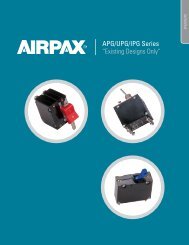
Single Pole<br />
<strong>IELR</strong> (Rail-Mount)<br />
.236<br />
[5.99]<br />
1.929<br />
[49.00]<br />
.138<br />
[3.51]<br />
DIM.ìAî<br />
.689<br />
[17.50]<br />
.689<br />
[17.50]<br />
.183<br />
[4.65]<br />
3.622<br />
[92.00]<br />
1.680<br />
[42.67] 1.122<br />
[28.50]<br />
1.417<br />
[35.99]<br />
2.500<br />
[63.50]<br />
ON<br />
OFF<br />
I<br />
O<br />
1.437<br />
[36.50]<br />
2.059<br />
[52.30]<br />
MOUNTING CLIP<br />
2 X 6-32 THREAD<br />
M3 X 0.5-6H THREAD OPTIONAL<br />
.142 [3.6] DEEP (TYP.)<br />
1.240<br />
[31.50]<br />
M5 SCREW<br />
Two Pole<br />
.236<br />
[5.99]<br />
1.929<br />
[49.00]<br />
.138<br />
[3.51]<br />
DIM.ìAî<br />
.689<br />
[17.50]<br />
.689<br />
[17.50]<br />
.183<br />
[4.65]<br />
3.622<br />
[92.00]<br />
1.680<br />
[42.67] 1.122<br />
[28.50]<br />
1.417<br />
[35.99]<br />
2.500<br />
[63.50]<br />
ON I ON I<br />
OFF O OFF O<br />
1.437<br />
[36.50]<br />
2.059<br />
[52.30]<br />
ALL MULTI-POLE CONFIGURATIONS<br />
USE TWO MOUNTING CLIPS<br />
1.240<br />
[31.50]<br />
4 X 6-32 THREAD<br />
M3 X 0.5-6H THREAD OPTIONAL<br />
.142 [3.6] DEEP (TYP.)<br />
.748<br />
[19.00]<br />
MULTI-POLE DIMENSIONS - DIM “A”<br />
Note: Tolerance ± .015 [.38] unless noted.<br />
Dimensions in brackets [ ] are millimeters.<br />
1 pole .750 ± .02 [19.05 ± .5] max<br />
2 pole 1.515 [38.48] max<br />
3 pole 2.265 [57.53] max<br />
4 pole 3.015 [76.58] max<br />
Note: Dimension “A” varies with # of poles<br />
<strong>IELR</strong> <strong>Series</strong> - Poles<br />
162
<strong>IELR</strong> SPECIFICATIONS<br />
<strong>Series</strong> Trip<br />
The most popular configuration for magnetic protectors is the<br />
series trip where the sensing coil and contacts are in series with<br />
the load being protected. The handle position conveniently<br />
indicates circuit status. In addition to providing conventional<br />
overcurrent protection, it’s simultaneously used as an on-off<br />
switch.<br />
Switch Only<br />
In the event that over-current protection is not desired, the coil<br />
mechanism can be deleted, providing an excellent low cost,<br />
single or multi-pole power switch.<br />
Insulation Resistance<br />
100 megohm minimum at 500Vdc between all electrically isolated<br />
terminals.<br />
Dielectric Strength<br />
3750Vac (3750V~) shall withstand AC voltages 50/60Hz for 60<br />
seconds between all electrically isolated terminals.<br />
Endurance<br />
Circuit breakers shall operate a minimum of 10,000 operations;<br />
6,000 with rated current and voltage and 4,000 with no load.<br />
Operating Temperature<br />
–40°C to +85°C.<br />
IEC 144 Classification<br />
Type handle spacings–IP40. Terminals–IP00.<br />
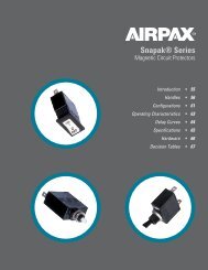
<strong>Series</strong><br />
Switch Only<br />
LINE<br />
LOAD<br />
Moisture Resistance<br />
10 days, 95 percent relative humidity at 40°C in accordance with<br />
IEC68-2-3, test C.<br />
Three Pole Schematic Diagram<br />
Salt Spray<br />
Five percent solution at 35°C in accordance with IEC68-2-11, test<br />
K, 48 hours.<br />
Shock<br />
50g, 11m sec, half sine with rated current, except no current with<br />
handle down. Instantaneous units use 80 percent rated current.<br />
Test in accordance with IEC68-2-27, test Ea. This assumes that<br />
adequate end stops are used to prevent longitudinal movement<br />
of the circuit protector.<br />
Vibration<br />
4g, 5–500Hz (maximum double amplitude displacement 1.5mm)<br />
with rated current except no current with handle down.<br />
Instantaneous units use 80 percent rated current, in accordance<br />
with IEC68-2-6, test F, method A, one hour per plane. This<br />
assumes that adequate end stops will be used to prevent<br />
longitudinal movement of the circuit protector.<br />
t=f (I)<br />
163<br />
<strong>IELR</strong> <strong>Series</strong> - Specifications<br />
http://airpax.sensata.com
<strong>IELR</strong> OPERATING CHARACTERISTICS<br />
<strong>IELR</strong> (Rail-Mount)<br />
APL/UPL - NOMINAL DCR / IMPEDANCE<br />
Current<br />
Ratings<br />
(Amps)<br />
Resistance (ohms) Impedance (ohms) Impedance (ohms)<br />
DC Delays AC, 50/60Hz Delays AC, 400Hz Delays<br />
51, 52, 53, 59 61, 62, 63, 69 41, 42, 43, 49<br />
0.20 45.8 28.5 71.94<br />
1.0 1.38 1.10 2.85<br />
5.0 .371 .29 .76<br />
10.0 .055 .051 .12<br />
15.0 .017 .016 .032<br />
20.0 .006 .006 .010<br />
30.0 .003 .004 .006<br />
50.0 .0019 .0018 .0019<br />
60.0 .00157 .00134 —<br />
70.0 .00147 .00133 —<br />
Notes: DCR and impedance based on 100% rated current applied and<br />
stabilized for a minimum of one hour. Tolerance .05-2.5 amperes ± 20%; 2.6-20<br />
amperes ± 25%; 21-70 amperes ± 50%. Consult factory for special values and<br />
for coil impedance of delays not shown.<br />
Inrush Pulse Tolerance<br />
Pulse tolerance is defined as a single pulse of half sine<br />
wave 50/60Hz peak current amplitude of 8 milliseconds<br />
duration that will not trip the circuit breaker.<br />
PULSE TOLERANCES<br />
Delay<br />
Pulse Tolerance<br />
61, 62, 63 (.1 to 70 amps) 12 times (approx.) rated current<br />
61F, 62F, 63F (.1 to 25 amps) 20 times (approx.) rated current<br />
61F, 62F, 63F (25.1 to 70 amps) 18 times (approx.) rated current<br />
PERCENTAGE OF RATED CURRENT VS TRIP TIME IN SECONDS AT +25°C<br />
Delay 100% 125% (Note A) 150% 200% 400% 600% 800% 1000%<br />
41 No Trip May trip .5 to 8 .15 to 1.9 .02 to 4 .006 to .25 .004 to .1 .004 to .05<br />
42 No Trip May trip 5 to 70 2.2 to 25 .40 to 5 .012 to 2 .006 to .2 .006 to .15<br />
43 No Trip May trip 35 to 350 12 to 120 1.5 to 20 .012 to 2.2 .01 to .22 .01 to .1<br />
49 No Trip May trip .100 max. .050 max. .020 max. .020 max. .020 max. .020 max.<br />
51 No Trip .5 to 6.5 .3 to 3 .1 to 1.2 .031 to .5 .011 to .25 .004 to .1 .004 to .08<br />
52 No Trip 2 to 60 1.8 to 30 1 to 10 .15 to 2 .04 to 1 .008 to .5 .006 to .1<br />
53 No Trip 80 to 700 40 to 400 15 to 150 2 to 20 .015 to 9 .015 to .55 .012 to .2<br />
59 No Trip .120 max. .100 max. .050 max. .022 max. .017 max. .017 max. .017 max.<br />
61 No Trip .7 to 12 .35 to 7 .130 to 3 .030 to 1 .015 to .3 .01 to .15 .008 to .1<br />
62 No Trip 10 to 120 6 to 60 2 to 20 .2 to 3 .02 to 2 .015 to .8 .01 to .25<br />
63 No Trip 50 to 700 30 to 400 10 to 150 1.5 to 20 .4 to 10 .013 to .85 .013 to .5<br />
69 No Trip .120 max. .100 max. .050 max. .022 max. .017 max. .017 max. .017 max.<br />
71 No Trip .44 to 10 .3 to 7 .1 to 3 .03 to 1 .012 to .3 .004 to .15 .004 to .1<br />
72 No Trip 1.8 to 100 1.7 to 60 1 to 20 .15 to 3 .015 to 2 .008 to .79 .006 to .28<br />
73 No Trip 50 to 600 30 to 400 10 to 150 1.8 to 20 .015 to 10 .015 to .88 .011 to .5<br />
79 No Trip .120 max. .100 max. .050 max. .023 max. .016 max. .015 max. .015 max.<br />
Notes: All trip times and trip currents are specified with the protector mounted in the normal vertical position at ambient temperature of 25 C.<br />
Protectors do not carry current prior to application of overload.<br />
A: 135% for delays 71, 72, 73 and 79.<br />
<strong>IELR</strong> <strong>Series</strong> - Operating Characteristics<br />
164
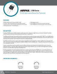
<strong>IELR</strong> DELAY CURVES<br />
400Hz, DC, 50/60Hz Delay Curves (typ)<br />
A choice of delays is offered for DC, 50/60Hz, 400Hz, or combined<br />
DC/50/60Hz applications. Delays 49, 59, 69 and 79 provide fast<br />
acting, instantaneous tripping and are often used to protect<br />
sensitive electronic equipment (not recommended where a<br />
known inrush exists). Delays 41, 51, 61 and 71 have a short delay<br />
for general purpose applications. Delays 42, 52, 62 and 72 are<br />
long enough for most transformers and capacitor loads. Delays<br />
43, 53, 63 and 73 are extra long for special motor applications.<br />
50/60Hz Delay Curves (typ)<br />
10000<br />
10000<br />
1000<br />
DELAY 61<br />
1000<br />
MAY TRIP<br />
DELAY 63<br />
TIME IN SECONDS<br />
100<br />
10<br />
1<br />
MAY TRIP<br />
TIME IN SECONDS<br />
100<br />
10<br />
1<br />
.1<br />
.1<br />
.01<br />
.01<br />
.001<br />
0 100<br />
125<br />
150 200 300 400 500 600 700 800<br />
900 1000<br />
.001<br />
0 100<br />
125<br />
150 200 300 400 500 600 700 800<br />
900 1000<br />
PERCENT OF RATED CURRENT<br />
PERCENT OF RATED CURRENT<br />
10000<br />
10000<br />
1000<br />
DELAY 62 1000<br />
DELAY 69<br />
TIME IN SECONDS<br />
100<br />
10<br />
1<br />
MAY TRIP<br />
TIME IN SECONDS<br />
100<br />
10<br />
1<br />
MAY TRIP<br />
.1<br />
.1<br />
.01<br />
.01<br />
.001<br />
0 100<br />
125<br />
150 200 300 400 500 600 700 800<br />
900 1000<br />
.001<br />
0 100<br />
125<br />
150 200 300 400 500 600 700 800<br />
900 1000<br />
PERCENT OF RATED CURRENT<br />
PERCENT OF RATED CURRENT<br />
165<br />
<strong>IELR</strong> <strong>Series</strong> - Delay Curves<br />
http://airpax.sensata.com
10000<br />
10000<br />
1000<br />
1000<br />
MAY TRIP<br />
<strong>IELR</strong> (Rail-Mount)<br />
DC Delay Curves (typ)<br />
DELAY 51<br />
DELAY 53<br />
TIME IN SECONDS<br />
100<br />
10<br />
1<br />
MAY TRIP<br />
TIME IN SECONDS<br />
100<br />
10<br />
1<br />
.1<br />
.1<br />
.01<br />
.01<br />
.001<br />
0 100<br />
125<br />
150 200 300 400 500 600 700 800<br />
900 1000<br />
.001<br />
0 100<br />
125<br />
150 200 300 400 500 600 700 800<br />
900 1000<br />
PERCENT OF RATED CURRENT<br />
PERCENT OF RATED CURRENT<br />
10000<br />
10000<br />
TIME IN SECONDS<br />
1000<br />
100<br />
10<br />
1<br />
MAY TRIP<br />
DELAY 52<br />
TIME IN SECONDS<br />
1000<br />
100<br />
10<br />
1<br />
MAY TRIP<br />
DELAY 59<br />
.1<br />
.1<br />
.01<br />
.01<br />
.001<br />
0 100<br />
125<br />
150 200 300 400 500 600 700 800<br />
900 1000<br />
.001<br />
0 100<br />
125<br />
150 200 300 400 500 600 700 800<br />
900 1000<br />
PERCENT OF RATED CURRENT<br />
PERCENT OF RATED CURRENT<br />
<strong>IELR</strong> <strong>Series</strong> - Delay Curves<br />
166
DC/50/60Hz Delay Curves (typ)<br />
(Multi-Frequency)<br />
10000<br />
10000<br />
1000<br />
100<br />
MAY TRIP<br />
DELAY 71<br />
DC/50/60 Hz<br />
Short Delay<br />
1000<br />
100<br />
MAY TRIP<br />
DELAY 73<br />
DC/50/60 Hz<br />
Motor Start Delay<br />
TIME IN SECONDS<br />
10<br />
1<br />
TIME IN SECONDS<br />
10<br />
1<br />
.1<br />
.1<br />
.01<br />
.01<br />
.001<br />
0 100<br />
135<br />
150 200 300 400 500 600 700 800<br />
900 1000<br />
.001<br />
0 100<br />
135<br />
150 200 300 400 500 600 700 800<br />
900 1000<br />
PERCENT OF RATED CURRENT<br />
PERCENT OF RATED CURRENT<br />
10000<br />
10000<br />
1000<br />
100<br />
MAY TRIP<br />
DELAY 72<br />
DC/50/60 Hz<br />
Long Delay<br />
1000<br />
100<br />
DELAY 79<br />
DC/50/50 Hz<br />
135% Instant Trip<br />
TIME IN SECONDS<br />
10<br />
1<br />
TIME IN SECONDS<br />
10<br />
1<br />
MAY TRIP<br />
.1<br />
.1<br />
.01<br />
.01<br />
.001<br />
0 100<br />
135<br />
150 200 300 400 500 600 700 800<br />
900 1000<br />
.001<br />
0 100<br />
135<br />
150 200 300 400 500 600 700 800<br />
900 1000<br />
PERCENT OF RATED CURRENT<br />
PERCENT OF RATED CURRENT<br />
167<br />
<strong>IELR</strong> <strong>Series</strong> - Delay Curves<br />
http://airpax.sensata.com
10000<br />
10000<br />
1000<br />
DELAY 41<br />
1000<br />
MAY TRIP<br />
DELAY 43<br />
100<br />
MAY TRIP<br />
100<br />
TIME IN SECONDS<br />
<strong>IELR</strong> (Rail-Mount)<br />
400Hz Delay Curves (typ)<br />
10<br />
1<br />
TIME IN SECONDS<br />
10<br />
1<br />
.1<br />
.1<br />
.01<br />
.01<br />
.001<br />
0 100<br />
125<br />
150 200 300 400 500 600 700 800<br />
900 1000<br />
.001<br />
0 100<br />
125<br />
150200 300 400 500 600 700 800<br />
900 1000<br />
PERCENT OF RATED CURRENT<br />
PERCENT OF RATED CURRENT<br />
10000<br />
10000<br />
1000<br />
100<br />
MAY TRIP<br />
DELAY 42 1000<br />
DELAY 49<br />
100<br />
TIME IN SECONDS<br />
10<br />
1<br />
TIME IN SECONDS<br />
10<br />
1<br />
MAY TRIP<br />
.1<br />
.1<br />
.01<br />
.01<br />
.001<br />
0 100<br />
125<br />
150 200 300 400 500 600 700 800<br />
900 1000<br />
.001<br />
0 100<br />
125<br />
150 200 300 400 500 600 700 800<br />
900 1000<br />
PERCENT OF RATED CURRENT<br />
PERCENT OF RATED CURRENT<br />
<strong>IELR</strong> <strong>Series</strong> - Delay Curves<br />
168
AGENCY APPROVALS<br />
Voltage (Volts) Rated Current (Amps) Interrupting Capacity, Amps<br />
Max Voltage Frequency (Hz) Phase Min Poles UL/CSA VDE UL1077 & CSA VDE<br />
80 DC — 1 .05 to 50 .10 - 50 u2, 1000 4000<br />
80 DC — 1 .05 to 100 — u2, 5000 —<br />
250 50/60 1 & 3 1 .05 to 50 .10 - 50 3500 2000<br />
250 50/60 1 & 3 1 .05 to 70 — 2000 —<br />
250 50/60 1 & 3 1 .05 to 50 — 5000 (1) —<br />
250 50/60 1 & 3 1 .05 to 70 — 5000 (1) —<br />
277 50/60 1 1 .05 to 50 — 2000 —<br />
277 50/60 1 1 .05 to 50 — 5000 (1) —<br />
240/415 50/60 1 & 3 2 .05 to 50 .10 - 30 2000 2000<br />
240/415 50/60 1 & 3 2 .05 to 50 — 5000 (1) —<br />
277/480 50/60 3 2 .05 to 30 — 2000 —<br />
250 400 1 & 3 1 .05 to 50 — 1750 —<br />
Note: (1) with 125A max series fuse.<br />
<strong>IELR</strong> DECISION TABLES<br />
How to Order<br />
The ordering code for <strong>IELR</strong> circuit protectors may be determined by<br />
following the steps in the decision tables shown here.<br />
The coding given permits a self-assigning part number, but with<br />
limitations. Using the illustrated coding system, it will<br />
automatically be assumed that all poles are identical. When all<br />
poles of a multi-pole protector are not identical, please contact<br />
an <strong>Airpax</strong> sales representative or the factory for a part number.<br />
One great virtue of magnetic circuit protectors is their adaptability<br />
to complex circuits. Thus, variations from pole to pole can<br />
become the rule rather than the exception. Descriptive drawings<br />
are recommended to avoid confusion.<br />
Notes:<br />
When poles are not identical, each pole is to be described and a<br />
special <strong>Airpax</strong> number will be assigned.<br />
Thomas & Betts (T&B) Narrow Tongue Lug P/N 54108NT is<br />
recommended for units rated above 50A. The T&B lug or an<br />
equivalent must be used on units rated 70A and above.<br />
When specifying a protector for AC motor start or high inrush<br />
applications, it is helpful to know the peak amplitude and surge<br />
duration for proper protector selection.<br />
169<br />
<strong>IELR</strong> <strong>Series</strong> - Approvals & Decision Tables<br />
http://airpax.sensata.com
1<br />
IALHR<br />
First Decision<br />
Type<br />
One handle per pole<br />
(multi-pole only)<br />
5<br />
Fifth Decision<br />
Rated Current<br />
Standard ratings listed. For other ratings,<br />
please contact the factory.<br />
<strong>IELR</strong> (Rail-Mount)<br />
IULHR<br />
One handle per pole<br />
(multi-pole only)<br />
UL Recognized, CSA Certified<br />
and VDE Approved ratings<br />
.100<br />
.250<br />
.500<br />
10.0<br />
15.0<br />
20.0<br />
IELHR<br />
IALR<br />
IULR<br />
<strong>IELR</strong><br />
One handle per pole<br />
(multi-pole only)<br />
UL Recognized, CSA Certified<br />
and VDE Approved ratings<br />
One handle per unit<br />
One handle per unit<br />
UL Recognized<br />
and CSA Certified ratings<br />
One handle per unit<br />
UL Recognized, CSA Certified<br />
and VDE Approved ratings<br />
Example:<br />
<strong>IELR</strong> 1 - 1 - 61 - 20.0 - 01 - V<br />
1 2 3 4 5 7<br />
.750<br />
1.0<br />
2.5<br />
5.0<br />
7.5<br />
30.0<br />
35.0<br />
40.0<br />
50.0<br />
60.0<br />
70.0<br />
Use three numbers to print required value<br />
between .050 amperes minimum and<br />
70.0 amperes maximum.<br />
IMLR<br />
IMLHR<br />
Mid-trip indication,<br />
One handle per unit<br />
Mid-trip indication,<br />
One handle per pole<br />
6<br />
Sixth Decision<br />
Optional<br />
Standard hardware.<br />
No designation necessary.<br />
2<br />
Second Decision<br />
-A<br />
Metric thread mounting<br />
inserts<br />
Poles<br />
-C<br />
277V (50/60Hz only)<br />
1<br />
Single pole<br />
-D<br />
240/415V (50/60Hz only)<br />
11<br />
111<br />
1111<br />
3<br />
-0<br />
-1<br />
Two pole<br />
Three pole<br />
Four pole<br />
Third Decision<br />
Configuration<br />
Switch only<br />
(Omit 4th decision)<br />
<strong>Series</strong><br />
V = VDE Approved<br />
The shaded areas denote VDE Approval options. This<br />
approval requires the addition of a V at the end of the<br />
part number. The V will be added to any part number<br />
formed entirely from shaded decisions. If non-shaded<br />
areas are selected, the unit will not be VDE approved,<br />
but other approvals still apply.<br />
4<br />
SW<br />
-41<br />
-42<br />
-43<br />
-49<br />
-51<br />
-52<br />
-53<br />
-59<br />
-61<br />
-62<br />
-63<br />
-69<br />
-71<br />
-72<br />
-73<br />
-79<br />
Fourth Decision<br />
Frequency & Delay<br />
Switch Only<br />
400Hz short delay<br />
400Hz long delay<br />
400Hz motor start<br />
400Hz 150% instant trip<br />
DC short delay<br />
DC long delay<br />
DC motor start<br />
DC 125% instant trip<br />
50/60Hz short delay<br />
50/60Hz long delay<br />
50/60Hz motor start<br />
50/60Hz 125% instant trip<br />
DC/50/60 Hz short delay<br />
DC/50/60 Hz long delay<br />
DC/50/60 Hz motor start<br />
DC/50/60 Hz 135% instant trip<br />
For addition of inertial delay, add an “F” to any<br />
delay numeral.<br />
7<br />
-00<br />
-10<br />
-20<br />
-30<br />
-40<br />
-60<br />
-90<br />
-01<br />
-11<br />
-21<br />
-31<br />
-41<br />
-61<br />
-91<br />
(Std.)<br />
Seventh Decision<br />
Handle Color Selection<br />
Unmarked<br />
Black<br />
Yellow<br />
Red<br />
Blue<br />
Green<br />
Orange<br />
White<br />
Marked (Combination On - Off / I-O)<br />
Black with white markings<br />
Yellow with black markings<br />
Red with white markings<br />
Blue with white markings<br />
Green with white markings<br />
Orange with black markings<br />
White with black markings
©2013 <strong>Sensata</strong> Technologies, Inc. All rights reserved worldwide. The following data sheet is an excerpt from our <strong>Airpax</strong> Power<br />
Protection Catalog, Literature # 2455005000, printed in the USA, May 9th, 2013.<br />
Important Notice: <strong>Sensata</strong> Technologies reserves the right to make changes to, or to discontinue, any product or service identified in<br />
this publication without notice. Before placing orders, users should obtain the latest version of the relevant information to verify that<br />
the information being relied upon is current.<br />
<strong>Sensata</strong> Technologies assumes no responsibility for customers’ product designs or applications. Users must determine the suitability<br />
of the <strong>Sensata</strong> device described in this publication for their application, including the level of reliability required. Many factors beyond<br />
<strong>Sensata</strong>’s control can affect the use and performance of a <strong>Sensata</strong> product in a particular application, including the conditions under<br />
which the product is used and the time and environmental conditions in which the product is expected to perform. As these factors<br />
are uniquely within the user’s knowledge and control, it is essential that the user evaluate the <strong>Sensata</strong> product to determine whether it<br />
is fit for a particular purpose and suitable for the user’s application.<br />
<strong>Sensata</strong> Technologies products are sold subject to <strong>Sensata</strong>’s Terms and Conditions of Sale which can be found at:<br />
www.sensata.com/terms.htm<br />
<strong>Sensata</strong> Technologies Inc.<br />
529 Pleasant Street<br />
Attleboro, MA 02703, USA<br />
Phone: +1 508-236-3287<br />
http://airpax.sensata.com/