250 Series DIN Rail and Wall Mounted Relays - Crompton Western ...
250 Series DIN Rail and Wall Mounted Relays - Crompton Western ...
250 Series DIN Rail and Wall Mounted Relays - Crompton Western ...

Create successful ePaper yourself
Turn your PDF publications into a flip-book with our unique Google optimized e-Paper software.
<strong>250</strong> <strong>Series</strong> <strong>DIN</strong> <strong>Rail</strong> <strong>and</strong> <strong>Wall</strong> <strong>Mounted</strong> <strong>Relays</strong><br />
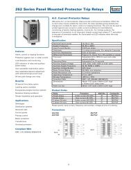
Reverse Power (Current)<br />
The reverse power protector provides continuous surveillance for A.C. generators<br />
operating in parallel or for boosting mains supplies. On site adjustment of the trip<br />
point <strong>and</strong> time delay ensures accurate protection against ‘motoring’ in the event of<br />
engine failure <strong>and</strong> prevents tripping from surges during synchronizing.<br />
Features<br />
Three phase, 3 or 4 wire<br />
Adjustable setpoint<br />
Adjustable time delay<br />
Internal differential<br />
LED trip indication<br />
Double pole relay contacts<br />
Automatic reset<br />
Benefits<br />
Current <strong>and</strong> power factor measurement<br />
Protects generators againsts ‘motoring’<br />
Detects reverse power under fault<br />
conditions<br />
Customized options<br />
Nuisance tripping avoidance<br />
Applications<br />
Marine panels<br />
Switchgear<br />
Distribution systems<br />
Generator sets<br />
Control panels<br />
Process control<br />
Motor protection<br />
Transformers<br />
Overload protection<br />
Approvals<br />
UL, CSA, BV <strong>and</strong> ABS<br />
Operation<br />
Reverse power protectors provide continuous surveillance of AC generators against<br />
motoring. Reverse power relays are used to detect the failure of the prime mover<br />
(engine) when active energy (Watts) flows into the generator causing rotation - the<br />
set will operate like an electric motor, which can cause significant mechanical<br />
damage. This relay offers an adjustable reverse power setpoint between 2% <strong>and</strong> 20%<br />
of nominal power, <strong>and</strong> time delay adjustment range of 0 to 20 seconds.<br />
As soon as the reverse power level increases above the setpoint limit, the time delay<br />
is activated, after which a trip will occur. The time delay prevents the relay from<br />
tripping for a predetermined period to prevent nuisance tripping. The products also<br />
feature an internal differential (hysteresis) setting of 1% to reduce nuisance tripping if<br />
the measured signal is noisy or unstable. These units are powered from the<br />
measuring supply.<br />
The protector relay approximates the power level in the system by measuring<br />
current <strong>and</strong> power factor, but does not actually measure the system voltage. When<br />
the reverse power level exceeds the setpoint, the time delay is started. When the<br />
time has elapsed, the relay will energize <strong>and</strong> the red LED will illuminate to indicate<br />
the trip condition. The relay will automatically reset once the power level falls<br />
below the setpoint minus the differential, the LED will extinguish <strong>and</strong> the relay<br />
de-energizes. The time delay is not active when resetting. The reverse power level<br />
will trip as expected at the calibrated point for unity power factor, however, the<br />
system power factor does affect the trip point calibration. The relay becomes more<br />
sensitive at lagging power factors, as almost all systems exhibit inductance.<br />
At leading power factors, this relay is less sensitive.<br />
Setting Up<br />
The “% set” potentiometer trimmer on the front label is calibrated as a percentage of<br />
the input current rating e.g. of 5A, <strong>and</strong> not of the forward kW. Adjust the “% set”<br />
trimmer to the required tripping value, 7.5% to 10% is normal. Setting accuracy can<br />
be checked by reversing the current lead connections <strong>and</strong>, with forward power,<br />
measuring the trip point value on a suitable ammeter (reconnect leads on<br />
completion). Adjust the ‘Delay’ to the required time delay, 10 seconds is<br />
normally adequate.<br />
Options<br />
<strong>250</strong> series protector relays offer various customized options to suit individual<br />
requirements. Please consult factory.<br />
• Adjustment ranges - different adjustment ranges are possible for the setpoint<br />
<strong>and</strong> time delay controls.<br />
• Relay operation - st<strong>and</strong>ard models are fail safe, but the relays can be customized<br />
to de-energize on trip.<br />
Product Codes<br />
Relay Protection ANSI No. Catalog No.<br />
Single phase or Reverse power 2 – 20% 32 256-PAS<br />
3 phase 4 wire<br />
Single phase or 3 phase Reverse power 2 – 20% 32 256-PAQ<br />
4 wire push to test<br />
3 phase 3 wire push Reverse power 2 – 20% 32 256-PAR<br />
to test<br />
3 phase 3 wire Reverse power 2 – 20% 32 256-PAT<br />
Specify system voltage, frequency <strong>and</strong> required options at time of ordering.<br />
34