prEN 1996-1-1 51_e_stf.pdf - Confined Masonry Network
prEN 1996-1-1 51_e_stf.pdf - Confined Masonry Network
prEN 1996-1-1 51_e_stf.pdf - Confined Masonry Network

You also want an ePaper? Increase the reach of your titles
YUMPU automatically turns print PDFs into web optimized ePapers that Google loves.
EUROPEAN STANDARD<br />
NORME EUROPÉENNE<br />
EUROPÄISCHE NORM<br />
FINAL DRAFT<br />
<strong>prEN</strong> <strong>1996</strong>-1-1<br />
April 2004<br />
ICS 91.010.30 Will supersede ENV <strong>1996</strong>-1-1:1995<br />
English version<br />
Eurocode 6: Design of masonry structures - Part 1-1: Common<br />
rules for reinforced and unreinforced masonry structures<br />
Eurocode 6: Calcul des ouvrages en maçonnerie - Partie 1-<br />
1 : Règles communes pour ouvrages en maçonnerie<br />
armée et non armée<br />
Eurocode 6: Bemessung und Konstruktion von<br />
Mauerwerksbauten - Teil 1-1: Allgemeine Regeln für<br />
bewehrtes und unbewehrtes Mauerwerk<br />
This draft European Standard is submitted to CEN members for formal vote. It has been drawn up by the Technical Committee CEN/TC<br />
250.<br />
If this draft becomes a European Standard, CEN members are bound to comply with the CEN/CENELEC Internal Regulations which<br />
stipulate the conditions for giving this European Standard the status of a national standard without any alteration.<br />
This draft European Standard was established by CEN in three official versions (English, French, German). A version in any other<br />
language made by translation under the responsibility of a CEN member into its own language and notified to the Management Centre has<br />
the same status as the official versions.<br />
CEN members are the national standards bodies of Austria, Belgium, Cyprus, Czech Republic, Denmark, Estonia, Finland, France,<br />
Germany, Greece, Hungary, Iceland, Ireland, Italy, Latvia, Lithuania, Luxembourg, Malta, Netherlands, Norway, Poland, Portugal, Slovakia,<br />
Slovenia, Spain, Sweden, Switzerland and United Kingdom.<br />
Warning : This document is not a European Standard. It is distributed for review and comments. It is subject to change without notice and<br />
shall not be referred to as a European Standard.<br />
EUROPEAN COMMITTEE FOR STANDARDIZATION<br />
COMITÉ EUROPÉEN DE NORMALISATION<br />
EUROPÄISCHES KOMITEE FÜR NORMUNG<br />
Management Centre: rue de Stassart, 36<br />
B-1050 Brussels<br />
© 2004 CEN All rights of exploitation in any form and by any means reserved<br />
worldwide for CEN national Members.<br />
Ref. No. <strong>prEN</strong> <strong>1996</strong>-1-1:2004: E
<strong>prEN</strong> <strong>1996</strong>-1-1:2003 (E)<br />
Contents<br />
Page<br />
Background to the Eurocode programme......................................................................................... 7<br />
Status and field of application of Eurocodes..................................................................................... 8<br />
National Standards implementing Eurocodes .................................................................................. 9<br />
Links between Eurocodes and harmonised technical specifications (ENs and ETAs) for<br />
products .................................................................................................................................... 9<br />
National Annex for EN <strong>1996</strong>-1-1 ...................................................................................................... 10<br />
1 General ................................................................................................................................... 11<br />
1.1 Scope ....................................................................................................................................... 11<br />
1.1.1 Scope of Eurocode 6 .............................................................................................................. 11<br />
1.1.2 Scope of Part 1-1 of Eurocode 6 ...........................................................................................11<br />
1.1.3 Further Parts of Eurocode 6................................................................................................. 12<br />
1.2 Normative references ............................................................................................................ 13<br />
1.2.1 General ................................................................................................................................... 13<br />
1.2.2 Reference standards .............................................................................................................. 13<br />
1.3 Assumptions ........................................................................................................................... 14<br />
1.4 Distinction between principles and application rules......................................................... 14<br />
1.5 Terms and Definitions........................................................................................................... 14<br />
1.5.1 General ................................................................................................................................... 14<br />
1.5.2 Terms relating to masonry.................................................................................................... 15<br />
1.5.3 Terms relating to strength of masonry................................................................................ 15<br />
1.5.4 Terms relating to masonry units .......................................................................................... 16<br />
1.5.5 Terms relating to mortar ...................................................................................................... 17<br />
1.5.6 Terms relating to concrete infill ........................................................................................... 18<br />
1.5.7 Terms relating to reinforcement .......................................................................................... 18<br />
1.5.8 Terms relating to ancillary components.............................................................................. 18<br />
1.5.9 Terms relating to mortar joints............................................................................................ 19<br />
1.5.10 Terms relating to wall types ................................................................................................. 19<br />
1.5.11 Miscellaneous terms .............................................................................................................. 20<br />
1.6 Symbols................................................................................................................................... 21<br />
2 Basis of design ........................................................................................................................ 27<br />
2.1 Basic requirements ................................................................................................................ 27<br />
2.1.1 General ................................................................................................................................... 27<br />
2.1.2 Reliability ............................................................................................................................... 27<br />
2.1.3 Design working life and durability....................................................................................... 27<br />
2.2 Principles of limit state design.............................................................................................. 27<br />
2.3 Basic variables........................................................................................................................ 28<br />
2.3.1 Actions .................................................................................................................................... 28<br />
2.3.2 Design values of actions......................................................................................................... 28<br />
2.3.3 Material and product properties.......................................................................................... 28<br />
2.4 Verification by the partial factor method............................................................................ 28<br />
2.4.1 Design values of material properties.................................................................................... 28<br />
2
<strong>prEN</strong> <strong>1996</strong>-1-1:2003 (E)<br />
2.4.2 Combination of actions ..........................................................................................................28<br />
2.4.3 Ultimate limit states ...............................................................................................................28<br />
2.4.4 Serviceability limit states.......................................................................................................29<br />
2.5 Design assisted by testing.......................................................................................................29<br />
3 Materials .................................................................................................................................30<br />
3.1 <strong>Masonry</strong> Units ........................................................................................................................30<br />
3.1.1 Types and grouping of masonry units..................................................................................30<br />
3.1.2 Properties of masonry units –compressive strength ...........................................................32<br />
3.2 Mortar .....................................................................................................................................32<br />
3.2.1 Types of masonry mortar ......................................................................................................32<br />
3.2.2 Specification of masonry mortar ..........................................................................................32<br />
3.2.3 Properties of mortar...............................................................................................................33<br />
3.3 Concrete infill .........................................................................................................................33<br />
3.3.1 General ....................................................................................................................................33<br />
3.3.2 Specification for concrete infill .............................................................................................33<br />
3.3.3 Properties of concrete infill ...................................................................................................33<br />
3.4 Reinforcing steel .....................................................................................................................34<br />
3.4.1 General ....................................................................................................................................34<br />
3.4.2 Properties of reinforcing steel bars.......................................................................................34<br />
3.4.3 Properties of prefabricated bed joint reinforcement ..........................................................34<br />
3.5 Prestressing steel ....................................................................................................................35<br />
3.6 Mechanical properties of masonry .......................................................................................35<br />
3.6.1 Characteristic compressive strength of masonry ................................................................35<br />
3.6.2 Characteristic shear strength of masonry............................................................................38<br />
3.6.3 Characteristic flexural strength of masonry........................................................................40<br />
3.6.4 Characteristic anchorage strength of reinforcement..........................................................42<br />
3.7 Deformation properties of masonry .....................................................................................43<br />
3.7.1 Stress-strain relationship.......................................................................................................43<br />
3.7.2 Modulus of elasticity ..............................................................................................................44<br />
3.7.3 Shear modulus ........................................................................................................................44<br />
3.7.4 Creep, moisture expansion or shrinkage and thermal expansion .....................................45<br />
3.8 Ancillary components ............................................................................................................45<br />
3.8.1 Damp proof courses ...............................................................................................................45<br />
3.8.2 Wall ties...................................................................................................................................45<br />
3.8.3 Straps, hangers and brackets ................................................................................................46<br />
3.8.4 Prefabricated lintels ...............................................................................................................46<br />
3.8.5 Prestressing devices................................................................................................................46<br />
4 Durability ................................................................................................................................46<br />
4.1 General ....................................................................................................................................46<br />
4.2 Classification of environmental conditions..........................................................................46<br />
4.3 Durability of masonry............................................................................................................46<br />
4.3.1 <strong>Masonry</strong> units .........................................................................................................................46<br />
4.3.2 Mortar .....................................................................................................................................46<br />
4.3.3 Reinforcing steel .....................................................................................................................46<br />
4.3.4 Prestressing steel ....................................................................................................................48<br />
4.3.5 Prestressing devices................................................................................................................48<br />
4.3.6 Ancillary components and support angles...........................................................................49<br />
4.4 <strong>Masonry</strong> below ground ..........................................................................................................49<br />
3
<strong>prEN</strong> <strong>1996</strong>-1-1:2003 (E)<br />
5 Structural analysis................................................................................................................. 49<br />
5.1 General ................................................................................................................................... 49<br />
5.2 Structural behaviour in accidental situations (other than earthquakes and fire)........... 50<br />
5.3 Imperfections ......................................................................................................................... 50<br />
5.4 Second order effects............................................................................................................... <strong>51</strong><br />
5.5 Analysis of structural members............................................................................................ <strong>51</strong><br />
5.5.1 <strong>Masonry</strong> walls subjected to vertical loading ....................................................................... <strong>51</strong><br />
5.5.2 Reinforced masonry members subjected to vertical loading............................................. 57<br />
5.5.3 <strong>Masonry</strong> shear walls subjected to shear loading ................................................................ 60<br />
5.5.4 Reinforced masonry members subjected to shear loading ................................................ 62<br />
5.5.5 <strong>Masonry</strong> walls subjected to lateral loading......................................................................... 62<br />
6 Ultimate Limit State .............................................................................................................. 64<br />
6.1 Unreinforced masonry walls subjected to mainly vertical loading................................... 64<br />
6.1.1 General ................................................................................................................................... 64<br />
6.1.2 Verification of unreinforced masonry walls subjected to mainly vertical loading.......... 64<br />
6.1.3 Walls subjected to concentrated loads................................................................................. 67<br />
6.2 Unreinforced masonry walls subjected to shear loading ................................................... 70<br />
6.3 Unreinforced masonry walls subjected to lateral loading ................................................. 70<br />
6.3.1 General ................................................................................................................................... 70<br />
6.3.2 Walls arching between supports .......................................................................................... 72<br />
6.3.3 Walls subjected to wind loading...........................................................................................73<br />
6.3.4 Walls subjected to lateral loading from earth and water .................................................. 73<br />
6.3.5 Walls subjected to lateral loading from accidental situations........................................... 73<br />
6.4 Unreinforced masonry walls subjected to combined vertical and lateral loading .......... 74<br />
6.4.1 General ................................................................................................................................... 74<br />
6.4.2 Method using Φ factor........................................................................................................... 74<br />
6.4.3 Method using apparent flexural strength............................................................................ 74<br />
6.4.4 Method using equivalent bending coefficients .................................................................... 74<br />
6.5 Ties .......................................................................................................................................... 74<br />
6.6 Reinforced masonry members subjected to bending, bending and axial loading, or<br />
axial loading ........................................................................................................................... 75<br />
6.6.1 General ................................................................................................................................... 75<br />
6.6.2 Verification of reinforced masonry members subjected to bending and/or axial<br />
loading..................................................................................................................................... 76<br />
6.6.3 Flanged Reinforced Members .............................................................................................. 78<br />
6.6.4 Deep beams............................................................................................................................. 80<br />
6.6.5 Composite lintels.................................................................................................................... 82<br />
6.7 Reinforced masonry members subjected to shear loading ................................................ 82<br />
6.7.1 General ................................................................................................................................... 82<br />
6.7.2 Verification of reinforced masonry walls subjected to horizontal loads in the plane<br />
of the wall ............................................................................................................................... 83<br />
6.7.3 Verification of reinforced masonry beams subjected to shear loading ............................ 84<br />
6.7.4 Verification of deep beams subjected to shear loading ...................................................... 85<br />
6.8 Prestressed masonry.............................................................................................................. 85<br />
6.8.1 General ................................................................................................................................... 85<br />
6.8.2 Verification of Members ....................................................................................................... 86<br />
6.9 <strong>Confined</strong> masonry.................................................................................................................. 87<br />
6.9.1 General ................................................................................................................................... 87<br />
6.9.2 Verification of members........................................................................................................ 87<br />
4
<strong>prEN</strong> <strong>1996</strong>-1-1:2003 (E)<br />
7 Serviceability Limit State ......................................................................................................87<br />
7.1 General ....................................................................................................................................87<br />
7.2 Unreinforced masonry walls .................................................................................................88<br />
7.3 Reinforced masonry members ..............................................................................................88<br />
7.4 Prestressed masonry members..............................................................................................88<br />
7.5 <strong>Confined</strong> masonry members .................................................................................................89<br />
7.6 Walls subjected to concentrated loads .................................................................................89<br />
8 Detailing ..................................................................................................................................89<br />
8.1 <strong>Masonry</strong> details ......................................................................................................................89<br />
8.1.1 <strong>Masonry</strong> materials..................................................................................................................89<br />
8.1.2 Minimum thickness of wall....................................................................................................89<br />
8.1.3 Minimum area of wall............................................................................................................90<br />
8.1.4 Bonding of masonry ...............................................................................................................90<br />
8.1.5 Mortar joints...........................................................................................................................91<br />
8.1.6 Bearings under concentrated loads ......................................................................................91<br />
8.2 Reinforcement details ............................................................................................................91<br />
8.2.1 General ....................................................................................................................................91<br />
8.2.2 Cover to reinforcing steel ......................................................................................................92<br />
8.2.3 Minimum area of reinforcement...........................................................................................92<br />
8.2.4 Size of reinforcing steel..........................................................................................................93<br />
8.2.5 Anchorage and laps................................................................................................................93<br />
8.2.6 Restraint of compression reinforcing steel...........................................................................97<br />
8.2.7 Spacing of reinforcing steel ...................................................................................................97<br />
8.3 Prestressing details.................................................................................................................98<br />
8.4 <strong>Confined</strong> masonry details ......................................................................................................98<br />
8.5 Connection of walls ................................................................................................................98<br />
8.5.1 Connection of walls to floors and roofs ................................................................................98<br />
8.5.2 Connection between walls......................................................................................................99<br />
8.6 Chases and recesses on walls ...............................................................................................100<br />
8.6.1 General ..................................................................................................................................100<br />
8.6.2 Vertical chases and recesses ................................................................................................101<br />
8.6.3 Horizontal and inclined chases............................................................................................101<br />
8.7 Damp proof courses .............................................................................................................102<br />
8.8 Thermal and long term movement .....................................................................................102<br />
9 Execution...............................................................................................................................102<br />
9.1 General ..................................................................................................................................102<br />
9.2 Design of structural members .............................................................................................103<br />
9.3 Loading of masonry .............................................................................................................103<br />
Annex A (informative) Consideration of partial factors relating to Execution.........................104<br />
Annex B (informative) Method for calculating the eccentricity of a stability core...................105<br />
Annex C (informative) A simplified method for calculating the out-of-plane eccentricity<br />
of loading on walls................................................................................................................107<br />
Annex D (informative) Determination of ρ 3 and ρ 4 .....................................................................111<br />
Annex E (informative) Bending moment coefficients, α 1 , in single leaf laterally loaded<br />
wall panels of thickness less than or equal to 250 mm......................................................112<br />
5
<strong>prEN</strong> <strong>1996</strong>-1-1:2003 (E)<br />
Annex F (informative) Limiting height and length to thickness ratios for walls under the<br />
serviceability limit state....................................................................................................... 117<br />
Annex G (informative) Reduction factor for slenderness and eccentricity............................... 119<br />
Annex H (informative) Enhancement factor as given in 6.1.3.................................................... 121<br />
Annex I (informative) Adjustment of lateral load for walls supported on three or four<br />
edges subjected to out-of-plane horizontal loading and vertical loading ....................... 122<br />
Annex J (informative) Reinforced masonry members subjected to shear loading:<br />
enhancement of f vd .............................................................................................................. 123<br />
6
<strong>prEN</strong> <strong>1996</strong>-1-1:2003 (E)<br />
Foreword<br />
This document (EN <strong>1996</strong>-1-1:2004) has been prepared by Technical Committee CEN/TC 250<br />
“Structural Eurocodes”, the secretariat of which is held by BSI.<br />
This document supersedes ENV <strong>1996</strong>-1-1:1995 and ENV <strong>1996</strong>-1-3:1998<br />
This European Standard shall be given the status of a national standard, either by publication of an<br />
identical text or by endorsement, at the latest by (date to be inserted after vote), and conflicting<br />
national standards shall be withdrawn at the latest by (date to be inserted after the vote).<br />
Background to the Eurocode programme<br />
In 1975, the Commission of the European Community decided on an action programme in the field<br />
of construction, based on article 95 of the Treaty. The objective of the programme was the<br />
elimination of technical obstacles to trade and the harmonisation of technical specifications.<br />
Within this action programme, the Commission took the initiative to establish a set of harmonised<br />
technical rules for the design of construction works which, in a first stage, would serve as an<br />
alternative to the national rules in force in the Member States and, ultimately, would replace them.<br />
For fifteen years, the Commission, with the help of a Steering Committee with Representatives of<br />
Member States, conducted the development of the Eurocodes programme, which led to the first<br />
generation of European codes in the 1980’s.<br />
In 1989, the Commission and the Member States of the EU and EFTA decided, on the basis of an<br />
agreement 1) between the Commission and CEN, to transfer the preparation and the publication of the<br />
Eurocodes to the CEN through a series of Mandates, in order to provide them with a future status of<br />
European Standard (EN). This links de facto the Eurocodes with the provisions of all the Council’s<br />
Directives and/or Commission’s Decisions dealing with European standards (e. g. the Council<br />
Directive 89/106/EEC on construction products - CPD - and Council Directives 93/37/EEC,<br />
92/50/EEC and 89/440/EEC on public works and services and equivalent EFTA Directives initiated<br />
in pursuit of setting up the internal market).<br />
The Structural Eurocode programme comprises the following standards generally consisting of a<br />
number of Parts:<br />
EN 1990, Eurocode: Basis of design for structural Eurocodesl<br />
EN 1991, Eurocode 1: Actions on structures.<br />
EN 1992, Eurocode 2: Design of concrete structures.<br />
1) Agreement between the Commission of the European Communities and the European Committee for Standardisation (CEN)<br />
concerning the work on EUROCODES for the design of building and civil engineering works (BC/CEN/03/89).<br />
7
<strong>prEN</strong> <strong>1996</strong>-1-1:2003 (E)<br />
EN 1993, Eurocode 3: Design of steel structures.<br />
EN 1994, Eurocode 4: Design of composite steel and concrete structures.<br />
EN 1995, Eurocode 5: Design of timber structures.<br />
EN <strong>1996</strong>, Eurocode 6: Design of masonry structures.<br />
EN 1997, Eurocode 7: Geotechnical design.<br />
EN 1998, Eurocode 8: Design of structures for earthquake resistance.<br />
EN 1999, Eurocode 9: Design of aluminium structures.<br />
Eurocode standards recognise the responsibility of regulatory authorities in each Member State and<br />
have safeguarded their right to determine values related to regulatory safety matters at national level<br />
where these continue to vary from State to State.<br />
Status and field of application of Eurocodes<br />
The Member States of the EU and EFTA recognise that Eurocodes serve as reference documents for<br />
the following purposes:<br />
⎯ as a means to prove compliance of building and civil engineering works with the essential<br />
requirements of Council Directive 89/106/EEC, particularly Essential Requirement N°1 ⎯<br />
Mechanical resistance and stability ⎯ and Essential Requirement N°2 ⎯ Safety in case of fire;<br />
⎯ as a basis for specifying contracts for construction works and related engineering services;<br />
⎯ as a framework for drawing up harmonised technical specifications for construction products<br />
(ENs and ETAs).<br />
The Eurocodes, as far as they concern the construction works themselves, have a direct relationship<br />
with the Interpretative Documents 2) referred to in Article 12 of the CPD, although they are of a<br />
different nature from harmonised product standards 3) . Therefore, technical aspects arising from the<br />
Eurocodes work need to be adequately considered by CEN Technical Committees and/or EOTA<br />
Working Groups working on product standards with a view to achieving full compatibility of these<br />
technical specifications with the Eurocodes.<br />
2) According to Article 3.3 of the CPD, the essential requirements (ERs) shall be given concrete form in interpretative documents for<br />
the creation of the necessary links between the essential requirements and the mandates for harmonised ENs and ETAGs/ETAs.<br />
3) According to Article 12 of the CPD the interpretative documents shall :<br />
a) give concrete form to the essential requirements by harmonising the terminology and the technical bases and indicating classes or<br />
levels for each requirement where necessary ;<br />
b) indicate methods of correlating these classes or levels of requirement with the technical specifications, e. g. methods of calculation<br />
and of proof, technical rules for project design, etc. ;<br />
c) serve as a reference for the establishment of harmonised standards and guidelines for European technical approvals.<br />
The Eurocodes, de facto, play a similar role in the field of the ER 1 and a part of ER 2.<br />
8
<strong>prEN</strong> <strong>1996</strong>-1-1:2003 (E)<br />
The Eurocode standards provide common structural design rules for everyday use for the design of<br />
whole structures and component products of both a traditional and an innovative nature. Unusual<br />
forms of construction or design conditions are not specifically covered and additional expert<br />
consideration will be required by the designer in such cases.<br />
National Standards implementing Eurocodes<br />
The National Standards implementing Eurocodes will comprise the full text of the<br />
Eurocode (including any annexes), as published by CEN, which may be preceded by a National title<br />
page and National foreword, and may be followed by a National Annex (informative).<br />
The National Annex may only contain information on those parameters which are left open in the<br />
Eurocode for national choice, known as Nationally Determined Parameters, to be used for the design<br />
of buildings and civil engineering works to be constructed in the country concerned, i. e.:<br />
⎯ values and/or classes where alternatives are given in the Eurocode,<br />
⎯ values to be used where a symbol only is given in the Eurocode,<br />
⎯ country specific data (geographical, climatic etc), e.g. snow map,<br />
⎯ the procedure to be used where alternative procedures are given in the Eurocode<br />
and it may also contain:<br />
⎯ decisions on the application of informative annexes,<br />
⎯ references to non-contradictory complementary information to assist the user to apply the<br />
Eurocode.<br />
Links between Eurocodes and harmonised technical specifications (ENs and<br />
ETAs) for products<br />
There is a need for consistency between the harmonised technical specifications for construction<br />
products and the technical rules for works 4) . Furthermore, all the information accompanying the CE<br />
Marking of the construction products, which refer to Eurocodes, shall clearly mention which<br />
Nationally Determined Parameters have been taken into account.<br />
This European Standard is Part of EN <strong>1996</strong> which comprises the following Parts:<br />
EN <strong>1996</strong>-1-1: General- Rules for reinforced and unreinforced masonry<br />
NOTE This Part combines ENV <strong>1996</strong>-1-1 and ENV <strong>1996</strong>-1-3.<br />
EN <strong>1996</strong>-1-2: General-Structural fire design.<br />
4) see Article 3.3 and Article 12 of the CPD, as well as clauses 4.2, 4.3.1, 4.3.2 and 5.2 of ID 1.<br />
9
<strong>prEN</strong> <strong>1996</strong>-1-1:2003 (E)<br />
EN <strong>1996</strong>-2: Selection of materials and execution of masonry.<br />
EN <strong>1996</strong>-3: Simplified calculation methods<br />
EN <strong>1996</strong>-1-1 describes the Principles and requirements for safety, serviceability and durability of<br />
masonry structures. It is based on the limit state concept used in conjunction with a partial factor<br />
method.<br />
For the design of new structures, EN <strong>1996</strong>-1-1 is intended to be used, for direct application, together<br />
with ENs 1990, 1991, 1992, 1993, 1994, 1995, 1997, 1998 and 1999.<br />
EN <strong>1996</strong>-1-1 is intended for use by:<br />
⎯ committees drafting standards for structural design and related products, testing and execution<br />
standards;<br />
⎯ clients (e. g. for the formulation of their specific requirements on reliability levels and<br />
durability);<br />
⎯ designers and contractors;<br />
⎯ relevant authorities.<br />
National Annex for EN <strong>1996</strong>-1-1<br />
This standard gives some symbols and some alternative methods for which a National value or<br />
choice needs to be given; notes under the relevant clauses indicate where national choices may have<br />
to be made. The National Standard implementing EN <strong>1996</strong>-1-1 in a particular country should have a<br />
National Annex containing all Nationally Determined Parameters to be used for the design of<br />
buildings and civil engineering works to be constructed in that country.<br />
National choice is allowed in EN <strong>1996</strong>-1-1 through clauses:<br />
⎯ 2.4.3(1)P Ultimate limit states;<br />
⎯ 2.4.4(1) Design value of material properties;<br />
⎯ 3.2.2(1) Specification of masonry mortar;<br />
⎯ 3.6.1.2(1) Characteristic compressive strength of masonry other than shell bedded;<br />
⎯ 3.6.2(3), (4) and (6) Characteristic shear strength of masonry;<br />
⎯ 3.6.3(3) Characteristic flexural strength of masonry;<br />
⎯ 3.7.2(2) Modulus of elasticity;<br />
⎯ 3.7.4(2) Creep, moisture expansion or shrinkage and thermal expansion;<br />
⎯ 4.3.3(3) and (4) Reinforcing steel;<br />
10
<strong>prEN</strong> <strong>1996</strong>-1-1:2003 (E)<br />
⎯ 5.5.1.3(3) Effective thickness of masonry walls;<br />
⎯ 6.1.2.2(2) Slenderness ratio λ c ;<br />
⎯ 8.5.2.2(2) Cavity walls;<br />
⎯ 8.5.2.3(2) Double-leaf walls.<br />
1 General<br />
1.1 Scope<br />
1.1.1 Scope of Eurocode 6<br />
(1)P Eurocode 6 applies to the design of buildings and civil engineering works, or parts thereof, in<br />
unreinforced, reinforced, prestressed and confined masonry.<br />
(2)P Eurocode 6 deals only with the requirements for resistance, serviceability and durability of<br />
structures. Other requirements, for example, concerning thermal or sound insulation, are not<br />
considered.<br />
(3)P Execution is covered to the extent that is necessary to indicate the quality of the construction<br />
materials and products that should be used and the standard of workmanship on site needed to<br />
comply with the assumptions made in the design rules.<br />
(4)P Eurocode 6 does not cover the special requirements of seismic design. Provisions related to such<br />
requirements are given in Eurocode 8 "Design of structures in seismic regions" which complements,<br />
and is consistent with, Eurocode 6.<br />
(5)P Numerical values of the actions on buildings and civil engineering works to be taken into<br />
account in the design are not given in Eurocode 6. They are provided in Eurocode 1 "Actions on<br />
structures".<br />
1.1.2 Scope of Part 1-1 of Eurocode 6<br />
(1)P The basis for the design of buildings and civil engineering works in masonry is given in this<br />
Part 1-1 of Eurocode 6, which deals with unreinforced masonry and reinforced masonry where the<br />
reinforcement is added to provide ductility, strength or improve serviceability. The principles of the<br />
design of prestressed masonry and confined masonry are given, but application rules are not provided.<br />
This Part is not valid for masonry with a plan area of less than 0,04 m 2 .<br />
(2) For those types of structures not covered entirely, for new structural uses for established materials,<br />
for new materials, or where actions and other influences outside normal experience have to be<br />
resisted, the principles and application rules given in this EN may be applicable, but may need to be<br />
supplemented.<br />
(3) Part 1-1 gives detailed rules which are mainly applicable to ordinary buildings. The applicability<br />
of these rules may be limited, for practical reasons or due to simplifications; any limits of<br />
applicability are given in the text where necessary.<br />
11
<strong>prEN</strong> <strong>1996</strong>-1-1:2003 (E)<br />
(4)P The following subjects are dealt with in Part 1-1:<br />
⎯ section 1 : General.<br />
⎯ section 2 : Basis of design.<br />
⎯ section 3 : Materials.<br />
⎯ section 4 : Durability.<br />
⎯ section 5 : Structural analysis.<br />
⎯ section 6 : Ultimate Limit States.<br />
⎯ section 7 : Serviceability Limit States.<br />
⎯ section 8 : Detailing.<br />
⎯ section 9 : Execution.<br />
(5)P Part 1-1 does not cover:<br />
⎯ resistance to fire (which is dealt with in EN <strong>1996</strong>-1-2);<br />
⎯ particular aspects of special types of building (for example, dynamic effects on tall buildings);<br />
⎯ particular aspects of special types of civil engineering works (such as masonry bridges, dams,<br />
chimneys or liquid-retaining structures);<br />
⎯ particular aspects of special types of structures (such as arches or domes);<br />
⎯ masonry where gypsum, with or without cement, mortars are used;<br />
⎯ masonry where the units are not laid in a regular pattern of courses (rubble masonry);<br />
⎯ masonry reinforced with other materials than steel.<br />
1.1.3 Further Parts of Eurocode 6<br />
(1) Part 1-1 of Eurocode 6 will be supplemented by further Parts as follows:<br />
⎯ Part 1-2: Structural fire design.<br />
⎯ Part 2: Selection of materials and execution of masonry.<br />
⎯ Part 3: Simplified calculation methods.<br />
12
<strong>prEN</strong> <strong>1996</strong>-1-1:2003 (E)<br />
1.2 Normative references<br />
1.2.1 General<br />
(1)P This European standard incorporates by dated or undated reference, provisions from other<br />
publications. These normative references are cited at the appropriate places in the text and the<br />
publications are listed hereafter. For dated references, subsequent amendments to, or revisions of,<br />
any of these publications apply to this European standard only when incorporated in it by<br />
amendment or revision. For undated references the latest edition of the publication referred to applies<br />
(including amendments).<br />
1.2.2 Reference standards<br />
The following standards are referenced in this EN <strong>1996</strong>-1-1:<br />
⎯ EN 206-1, Concrete ⎯ Part 1: Specification, performance, production and conformity.<br />
⎯ EN 771-1, Specification for masonry units ⎯ Part 1: Clay masonry units.<br />
⎯ EN 771-2, Specification for masonry units ⎯ Part 2: Calcium silicate masonry units.<br />
⎯ EN 771-3, Specification for masonry units ⎯ Part 3: Aggregate concrete masonry units (Dense<br />
and light-weight aggregates).<br />
⎯ EN 771-4, Specification for masonry units ⎯ Part 4: Autoclaved aerated concrete masonry units.<br />
⎯ EN 771-5, Specification for masonry units ⎯ Part 5: Manufactured stone masonry units.<br />
⎯ <strong>prEN</strong> 771-6, Specification for masonry units ⎯ Part 6: Natural stone masonry units.<br />
⎯ EN 772-1, Methods of test for masonry units ⎯ Part 1: Determination of compressive strength.<br />
⎯ EN 845-1, Specification for ancillary components for masonry ⎯ Part 1: Ties, tension straps,<br />
hangers and brackets.<br />
⎯ EN 845-2, Specification for ancillary components for masonry ⎯ Part 2: Lintels.<br />
⎯ EN 845-3, Specification for ancillary components for masonry ⎯ Part 3: Bed joint<br />
reinforcement of steel meshwork.<br />
⎯ EN 846-2, Methods of test for ancillary components for masonry ⎯ Part 2: Determination of<br />
bond strength of prefabricated bed joint reinforcement in mortar joints.<br />
⎯ EN 998-1, Specification for mortar for masonry ⎯ Part 1: Rendering and plastering mortar.<br />
⎯ EN 998-2, Specification for mortar for masonry ⎯ Part 2: <strong>Masonry</strong> mortar.<br />
⎯ EN 1015-11, Methods of test for mortar for masonry ⎯ Part 11: Determination of flexural and<br />
compressive strength of hardened mortar.<br />
⎯ EN 1052-1, Methods of test for masonry ⎯ Part 1: Determination of compressive strength.<br />
13
<strong>prEN</strong> <strong>1996</strong>-1-1:2003 (E)<br />
⎯ EN 1052-2, Methods of test for masonry ⎯ Part 2: Determination of flexural strength.<br />
⎯ EN 1052-3, Methods of test for masonry ⎯ Part 3: Determination of initial shear strength.<br />
⎯ EN 1052-4, Methods of test for masonry ⎯ Part 4: Determination of shear strength including<br />
damp proof course.<br />
⎯ <strong>prEN</strong> 1052-5, Methods of test for masonry ⎯ Part 5: Determination of bond strength by bond<br />
wrench method.<br />
⎯ EN 1990, Basis of design for structural Eurocodes<br />
⎯ EN 1991, Actions on structures.<br />
⎯ EN 1992, Design of concrete structures.<br />
⎯ EN 1993, Design of steel structures.<br />
⎯ EN 1994, Design of composite steel and concrete structures.<br />
⎯ EN 1995, Design of timber structures.<br />
⎯ EN <strong>1996</strong>-2, Selection of materials and execution of masonry.<br />
⎯ EN 1997, Geotechnical design.<br />
⎯ EN 1999, Design of aluminium structures.<br />
⎯ EN 10080, Steel for the reinforcement of concrete<br />
⎯ <strong>prEN</strong> 10088, Stainless steels<br />
⎯ <strong>prEN</strong> 10138, Prestressing steel.<br />
⎯ EN ISO 1461, Hot dip galvanized coatings on fabricated iron and steel articles ⎯ Specifications<br />
and test methods.<br />
1.3 Assumptions<br />
(1)P The assumptions given in 1.3 of EN 1990 apply to this EN <strong>1996</strong>-1-1.<br />
1.4 Distinction between principles and application rules<br />
(1)P The rules in 1.4 of EN 1990 apply to this EN <strong>1996</strong>-1-1.<br />
1.5 Terms and Definitions<br />
1.5.1 General<br />
(1) The terms and definitions given in EN 1990:2002, Clause 1.5, apply to this EN <strong>1996</strong>-1-1.<br />
14
<strong>prEN</strong> <strong>1996</strong>-1-1:2003 (E)<br />
(2) The terms and definitions used in this EN <strong>1996</strong>-1-1 are given the meanings contained in clauses<br />
1.5.2 to 1.5.11, inclusive.<br />
1.5.2 Terms relating to masonry<br />
1.5.2.1<br />
masonry<br />
an assemblage of masonry units laid in a specified pattern and joined together with mortar<br />
1.5.2.2<br />
unreinforced masonry<br />
masonry not containing sufficient reinforcement so as to be considered as reinforced masonry<br />
1.5.2.3<br />
reinforced masonry<br />
masonry in which bars or mesh are embedded in mortar or concrete so that all the materials act together<br />
in resisting action effects<br />
1.5.2.4<br />
prestressed masonry<br />
masonry in which internal compressive stresses have been intentionally induced by tensioned<br />
reinforcement<br />
1.5.2.5<br />
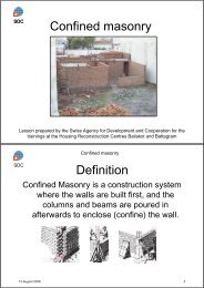
confined masonry<br />
masonry provided with reinforced concrete or reinforced masonry confining elements in the vertical and<br />
horizontal direction<br />
1.5.2.6<br />
masonry bond<br />
disposition of units in masonry in a regular pattern to achieve common action<br />
1.5.3 Terms relating to strength of masonry<br />
1.5.3.1<br />
characteristic strength of masonry<br />
value of the strength of masonry having a prescribed probability of 5% of not being attained in a<br />
hypothetically unlimited test series. This value generally corresponds to a specified fractile of the<br />
assumed statistical distribution of the particular property of the material or product in a test series. A<br />
nominal value is used as the characteristic value in some circumstances<br />
1.5.3.2<br />
compressive strength of masonry<br />
the strength of masonry in compression without the effects of platen restraint, slenderness or eccentricity<br />
of loading<br />
1.5.3.3<br />
shear strength of masonry<br />
the strength of masonry subjected to shear forces<br />
15
<strong>prEN</strong> <strong>1996</strong>-1-1:2003 (E)<br />
1.5.3.4<br />
flexural strength of masonry<br />
the strength of masonry in bending<br />
1.5.3.5<br />
anchorage bond strength<br />
the bond strength, per unit surface area, between reinforcement and concrete or mortar, when the<br />
reinforcement is subjected to tensile or compressive forces<br />
1.5.3.6<br />
adhesion<br />
the effect of mortar developing a tensile or shear resistance at the contact surface of masonry units<br />
1.5.4 Terms relating to masonry units<br />
1.5.4.1<br />
masonry unit<br />
a preformed component, intended for use in masonry construction<br />
1.5.4.2<br />
groups 1, 2, 3 and 4 masonry units<br />
group designations for masonry units, according to the percentage size and orientation of holes in the<br />
units when laid<br />
1.5.4.3<br />
bed face<br />
the top or bottom surface of a masonry unit when laid as intended<br />
1.5.4.4<br />
frog<br />
a depression, formed during manufacture, in one or both bed faces of a masonry unit<br />
1.5.4.5<br />
hole<br />
a formed void which may or may not pass completely through a masonry unit<br />
1.5.4.6<br />
griphole<br />
a formed void in a masonry unit to enable it to be more readily grasped and lifted with one or both hands<br />
or by machine<br />
1.5.4.7<br />
web<br />
the solid material between the holes in a masonry unit<br />
1.5.4.8<br />
shell<br />
the peripheral material between a hole and the face of a masonry unit<br />
16
<strong>prEN</strong> <strong>1996</strong>-1-1:2003 (E)<br />
1.5.4.9<br />
gross area<br />
the area of a cross-section through the unit without reduction for the area of holes, voids and re-entrants<br />
1.5.4.10<br />
compressive strength of masonry units<br />
the mean compressive strength of a specified number of masonry units (see EN 771-1 to EN 771-6)<br />
1.5.4.11<br />
normalized compressive strength of masonry units<br />
the compressive strength of masonry units converted to the air dried compressive strength of an<br />
equivalent 100 mm wide x 100 mm high masonry unit (see EN 771-1 to EN 771-6)<br />
1.5.5 Terms relating to mortar<br />
1.5.5.1<br />
masonry mortar<br />
mixture of one or more inorganic binders, aggregates and water, and sometimes additions and/or<br />
admixtures, for bedding, jointing and pointing of masonry<br />
1.5.5.2<br />
general purpose masonry mortar<br />
masonry mortar without special characteristics<br />
1.5.5.3<br />
thin layer masonry mortar<br />
designed masonry mortar with a maximum aggregate size less than or equal to a prescribed figure<br />
NOTE see note in 3.6.1.2 (2)<br />
1.5.5.4<br />
lightweight masonry mortar<br />
designed masonry mortar with a dry hardened density below a prescribed figure<br />
1.5.5.5<br />
designed masonry mortar<br />
a mortar whose composition and manufacturing method is chosen in order to achieve specified<br />
properties (performance concept)<br />
1.5.5.6<br />
prescribed masonry mortar<br />
mortar made in predetermined proportions, the properties of which are assumed from the stated<br />
proportions of the constituents (recipe concept)<br />
1.5.5.7<br />
factory made masonry mortar<br />
mortar batched and mixed in a factory<br />
1.5.5.8<br />
semi-finished factory made masonry mortar<br />
prebatched masonry mortar or a premixed lime and sand masonry mortar<br />
17
<strong>prEN</strong> <strong>1996</strong>-1-1:2003 (E)<br />
1.5.5.9<br />
prebatched masonry mortar<br />
mortar whose constituents are wholly batched in a factory, supplied to the building site and mixed there<br />
according to the manufacturers' specification and conditions<br />
1.5.5.10<br />
premixed lime and sand masonry mortar<br />
mortar whose constituents are wholly batched and mixed in a factory, supplied to the building site,<br />
where further constituents specified or provided by the factory are added (e. g. cement) and mixed with<br />
the lime and sand<br />
1.5.5.11<br />
site-made mortar<br />
a mortar composed of individual constituents batched and mixed on the building site<br />
1.5.5.12<br />
compressive strength of mortar<br />
the mean compressive strength of a specified number of mortar specimens after curing for 28 days<br />
1.5.6 Terms relating to concrete infill<br />
1.5.6.1<br />
concrete infill<br />
a concrete used to fill pre-formed cavities or voids in masonry<br />
1.5.7 Terms relating to reinforcement<br />
1.5.7.1<br />
reinforcing steel<br />
steel reinforcement for use in masonry<br />
1.5.7.2<br />
bed joint reinforcement<br />
reinforcing steel that is prefabricated for building into a bed joint<br />
1.5.7.3<br />
prestressing steel<br />
steel wires, bars or strands for use in masonry<br />
1.5.8 Terms relating to ancillary components<br />
1.5.8.1<br />
damp proof course<br />
a layer of sheeting, masonry units or other material used in masonry to resist the passage of water<br />
1.5.8.2<br />
wall tie<br />
a device for connecting one leaf of a cavity wall across a cavity to another leaf or to a framed structure<br />
or backing wall<br />
18
<strong>prEN</strong> <strong>1996</strong>-1-1:2003 (E)<br />
1.5.8.3<br />
strap<br />
a device for connecting masonry members to other adjacent components, such as floors and roofs<br />
1.5.9 Terms relating to mortar joints<br />
1.5.9.1<br />
bed joint<br />
a mortar layer between the bed faces of masonry units<br />
1.5.9.2<br />
perpend joint (head joint)<br />
a mortar joint perpendicular to the bed joint and to the face of wall<br />
1.5.9.3<br />
longitudinal joint<br />
a vertical mortar joint within the thickness of a wall, parallel to the face of the wall<br />
1.5.9.4<br />
thin layer joint<br />
a joint made with thin layer mortar<br />
1.5.9.5<br />
jointing<br />
the process of finishing a mortar joint as the work proceeds<br />
1.5.9.6<br />
pointing<br />
the process of filling and finishing mortar joints where the surface of the joint has been raked out or left<br />
open for pointing<br />
1.5.10 Terms relating to wall types<br />
1.5.10.1<br />
load-bearing wall<br />
a wall primarily designed to carry an imposed load in addition to its own weight<br />
1.5.10.2<br />
single-leaf wall<br />
a wall without a cavity or continuous vertical joint in its plane<br />
1.5.10.3<br />
cavity wall<br />
a wall consisting of two parallel single-leaf walls, effectively tied together with wall ties or bed joint<br />
reinforcement. The space between the leaves is left as a continuous cavity or filled or partially filled<br />
with non-loadbearing thermal insulating material<br />
NOTE A wall consisting of two leaves separated by a cavity, where one of the leaves is not contributing to the<br />
strength or stiffness of the other (possibly loadbearing) leaf, is to be regarded as a veneer wall.<br />
19
<strong>prEN</strong> <strong>1996</strong>-1-1:2003 (E)<br />
1.5.10.4<br />
double-leaf wall<br />
a wall consisting of two parallel leaves with the longitudinal joint between filled solidly with mortar and<br />
securely tied together with wall ties so as to result in common action under load<br />
1.5.10.5<br />
grouted cavity wall<br />
a wall consisting of two parallel leaves with the cavity filled with concrete or grout and securely tied<br />
together with wall ties or bed joint reinforcement so as to result in common action under load<br />
1.5.10.6<br />
faced wall<br />
a wall with facing units bonded to backing units so as to result in common action under load<br />
1.5.10.7<br />
shell bedded wall<br />
a wall in which the masonry units are bedded on two or more strips of mortar at the outside edges of the<br />
bed face of the units<br />
1.5.10.8<br />
veneer wall<br />
a wall used as a facing but not bonded or contributing to the strength of the backing wall or framed<br />
structure<br />
1.5.10.9<br />
shear wall<br />
a wall to resist lateral forces in its plane<br />
1.5.10.10<br />
stiffening wall<br />
a wall set perpendicular to another wall to give it support against lateral forces or to resist buckling and<br />
so to provide stability to the building<br />
1.5.10.11<br />
non-loadbearing wall<br />
a wall not considered to resist forces such that it can be removed without prejudicing the remaining<br />
integrity of the structure<br />
1.5.11 Miscellaneous terms<br />
1.5.11.1<br />
chase<br />
channel formed in masonry<br />
1.5.11.2<br />
recess<br />
indentation formed in the face of a wall<br />
1.5.11.3<br />
grout<br />
a pourable mixture of cement, sand and water for filling small voids or spaces<br />
20
<strong>prEN</strong> <strong>1996</strong>-1-1:2003 (E)<br />
1.5.11.4<br />
movement joint<br />
a joint permitting free movement in the plane of the wall<br />
1.6 Symbols<br />
(1) Material-independent symbols are given in 1.6 of EN 1990.<br />
(2) Material-dependent symbols used in this EN <strong>1996</strong>-1-1 are:<br />
Latin letters<br />
a 1<br />
a x<br />
A<br />
A<br />
A ef<br />
A s<br />
A sw<br />
b<br />
b c<br />
b ef<br />
b ef.l<br />
b ef.t<br />
c nom<br />
d<br />
d a<br />
d c<br />
e c<br />
e e<br />
e he<br />
distance from the end of a wall to the nearest edge of a loaded area;<br />
distance from the face of a support to the cross-section being considered;<br />
loaded horizontal gross cross-sectional area of a wall;<br />
loaded area;<br />
effective area of bearing;<br />
cross-sectional area of steel reinforcement;<br />
area of shear reinforcement;<br />
width of a section;<br />
width of the compression face midway between restraints;<br />
effective width of a flanged member;<br />
effective width of a flanged member;<br />
effective thickness of a flanged member;<br />
nominal concrete cover;<br />
effective depth of a beam;<br />
deflection of an arch under the design lateral load;<br />
largest dimension of the cross section of a core in the direction of bending;<br />
additional eccentricity;<br />
eccentricity at the top or the bottom of a wall;<br />
eccentricity at the top or bottom of a wall, resulting from horizontal loads;<br />
21
<strong>prEN</strong> <strong>1996</strong>-1-1:2003 (E)<br />
e hm<br />
e i<br />
e k<br />
e m<br />
e mk<br />
E<br />
E longterm<br />
eccentricity at the middle of a wall, resulting from horizontal loads;<br />
initial eccentricity;<br />
eccentricity due to creep;<br />
eccentricity due to loads;<br />
eccentricity at the middle of the wall;<br />
short term secant modulus of elasticity of masonry;<br />
long term modulus of elasticity of masonry;<br />
E n modulus of elasticity of member n;<br />
f b<br />
f bod<br />
f bok<br />
f ck<br />
f cvk<br />
f d<br />
f k<br />
f m<br />
f vd<br />
f vk<br />
f vko<br />
normalised mean compressive strength of a masonry unit;<br />
design anchorage strength of reinforcing steel;<br />
characteristic anchorage strength;<br />
characteristic compressive strength of concrete infill;<br />
characteristic shear strength of concrete infill;<br />
design compressive strength of masonry in the direction being considered;<br />
characteristic compressive strength of masonry;<br />
compressive strength of masonry mortar;<br />
design shear strength of masonry;<br />
characteristic shear strength of masonry;<br />
characteristic initial shear strength of masonry, under zero compressive stress;<br />
f vlt limit to the value of f vk ;<br />
f xd<br />
f xd1<br />
f xd1,app<br />
design flexural strength appropriate to the plane of bending;<br />
design flexural strength of masonry having the plane of failure parallel to the bed<br />
joints;<br />
apparent design flexural strength of masonry having the plane of failure parallel to the<br />
bed joints;<br />
22
<strong>prEN</strong> <strong>1996</strong>-1-1:2003 (E)<br />
f xk1<br />
f xd2<br />
f xd2,app<br />
f xk2<br />
f yd<br />
f yk<br />
F d<br />
g<br />
G<br />
h<br />
characteristic flexural strength of masonry having a plane of failure parallel to the bed<br />
joints;<br />
design flexural strength of masonry having the plane of failure perpendicular to the<br />
bed joints;<br />
apparent design flexural strength of masonry having the plane of failure perpendicular<br />
to the bed joints;<br />
characteristic flexural strength of masonry having a plane of failure perpendicular to<br />
the bed joints;<br />
design strength of reinforcing steel;<br />
characteristic strength of reinforcing steel<br />
design compressive or tensile resistance of a wall tie;<br />
total width of mortar strips;<br />
shear modulus of masonry;<br />
clear height of a masonry wall;<br />
h i clear height of masonry wall, i;<br />
h ef<br />
h tot<br />
h c<br />
effective height of a wall;<br />
total height of a structure from the top of the foundation, or a wall, or a core;<br />
height of a wall to the level of the load;<br />
I j second moment of area of member, j ;<br />
k<br />
k m<br />
k r<br />
K<br />
l<br />
l b<br />
l c<br />
ratio of the lateral load capacity of a vertically spanning wall to the lateral load<br />
capacity of the actual wall area, taking possible edge restraint into account;<br />
ratio of slab stiffness to wall stiffness<br />
rotational stiffness of a restraint;<br />
constant used in the calculation of the compressive strength of masonry;<br />
length of a wall (between other walls, between a wall and an opening, or between<br />
openings);<br />
straight anchorage length;<br />
length of the compressed part of a wall;<br />
23
<strong>prEN</strong> <strong>1996</strong>-1-1:2003 (E)<br />
l cl<br />
l ef<br />
l efm<br />
l r<br />
l a<br />
M<br />
ad<br />
clear length of an opening<br />
effective span of a masonry beam;<br />
effective length of a bearing at mid height of a wall;<br />
clear distance between lateral restraints;<br />
the length or the height of the wall between supports capable of resisting an arch<br />
thrust;<br />
additional design moment;<br />
M d<br />
design bending moment at the bottom of a core;<br />
M i end moment at node, i;<br />
M id<br />
M md<br />
M Rd<br />
M Ed<br />
M Edu<br />
M Edf<br />
n<br />
n i<br />
n t<br />
n tmin<br />
N<br />
N ad<br />
N id<br />
N md<br />
N Rd<br />
N Rdc<br />
design value of the bending moment at the top or the bottom of the wall;<br />
design value of the greatest moment at the middle of the height of the wall;<br />
design value of the moment of resistance;<br />
design value of the moment applied;<br />
design value of the moment above a floor;<br />
design value of the moment below a floor;<br />
number of storeys;<br />
stiffness factor of members;<br />
number of wall ties or connectors per m 2 of wall;<br />
minimum number of wall ties or connectors per m 2 of wall;<br />
sum of the design vertical actions on a building;<br />
the maximum design arch thrust per unit length of wall;<br />
design value of the vertical load at the top or bottom of a wall or column;<br />
design value of the vertical load at the middle of the height of a wall or column;<br />
design value of the vertical resistance of a masonry wall or column;<br />
design value of the vertical concentrated load resistance of a wall;<br />
24
<strong>prEN</strong> <strong>1996</strong>-1-1:2003 (E)<br />
N Ed<br />
N Edf<br />
N Edu<br />
N El<br />
N Edc<br />
q lat,d<br />
Q d<br />
r<br />
R e<br />
s<br />
E d<br />
t<br />
design value of the vertical load;<br />
design value of the load out of a floor;<br />
design value of the load above the floor;<br />
load applied by a floor;<br />
design value of a concentrated vertical load;<br />
design lateral strength per unit area of wall;<br />
design value of the total vertical load, in the part of a building stabilised by a core;<br />
arch rise;<br />
yield stress of steel;<br />
spacing of shear reinforcement;<br />
design value of the load applied to a reinforced masonry member;<br />
thickness of a wall;<br />
t i thickness of wall, i;<br />
t ef<br />
t f<br />
effective thickness of a wall;<br />
thickness of a flange;<br />
t ri thickness of the rib, i;<br />
V Ed<br />
V Rd<br />
design value of a shear load;<br />
design value of the shear resistance;<br />
w i uniformly distributed design load, i;<br />
W Ed<br />
x<br />
z<br />
Z<br />
design lateral load per unit area;<br />
depth to the neutral axis;<br />
lever arm;<br />
elastic section modulus of a unit height or length of the wall;<br />
Greek letters<br />
25
<strong>prEN</strong> <strong>1996</strong>-1-1:2003 (E)<br />
α<br />
angle of shear reinforcement to the axis of the beam;<br />
α t coefficient of thermal expansion of masonry ;<br />
α 1,2<br />
β<br />
bending moment coefficients;<br />
enhancement factor for concentrated loads;<br />
χ<br />
δ<br />
ε c∞<br />
ε el<br />
ε mu<br />
φ<br />
φ ∞<br />
Φ<br />
Φ fl<br />
Φ i<br />
Φ m<br />
γ M<br />
η<br />
λx<br />
λ c<br />
magnification factor for the shear resistance of reinforced walls;<br />
factor used in the determination of the normalised mean compressive strength of<br />
masonry units;<br />
final creep strain of masonry;<br />
elastic strain of masonry;<br />
limiting compressive strain in masonry;<br />
effective diameter of the reinforcing steel;<br />
final creep coefficient of masonry;<br />
reduction factor;<br />
reduction factor, taking the influence of the flexural strength into account;<br />
reduction factor at the top or bottom of the wall;<br />
reduction factor within the middle height of the wall;<br />
partial factor for materials, including uncertainties about geometry and modelling;<br />
factor for use in calculating the out-of-plane eccentricity of loading on walls;<br />
depth of the compressed zone in a beam, when using a rectangular stress block;<br />
value of the slenderness ratio up to which eccentricities due to creep can be neglected;<br />
µ orthogonal ratio of the flexural strengths of masonry;<br />
ξ<br />
ρ d<br />
ρ n<br />
magnification factor for the rotational stiffness of the restraint of the structural<br />
element being considered;<br />
dry density;<br />
reduction factor;<br />
26
<strong>prEN</strong> <strong>1996</strong>-1-1:2003 (E)<br />
ρ t<br />
stiffness coefficient;<br />
σ d design compressive stress ;<br />
υ<br />
angle of inclination to the vertical of the structure.<br />
2 Basis of design<br />
2.1 Basic requirements<br />
2.1.1 General<br />
(1)P The design of masonry structures shall be in accordance with the general rules given in EN 1990.<br />
(2)P Specific provisions for masonry structures are given in this section and shall be applied.<br />
(3) The basic requirements of EN 1990 Section 2 are deemed to be satisfied for masonry structures<br />
when the following are applied:<br />
⎯ limit state design in conjunction with the partial factor method described in EN 1990;<br />
⎯ actions given in EN 1991;<br />
⎯ combination rules given in EN 1990;<br />
⎯ the principles and rules of application given in this EN <strong>1996</strong>-1-1.<br />
2.1.2 Reliability<br />
(1)P The reliability required for masonry structures will be obtained by carrying out design according<br />
to this EN <strong>1996</strong>-1-1.<br />
2.1.3 Design working life and durability<br />
(1) For the consideration of durability reference should be made to Section 4.<br />
2.2 Principles of limit state design<br />
(1)P Limit states may concern only the masonry, or such other materials as are used for parts of the<br />
structure, for which reference shall be made to relevant Parts of EN 1992, EN 1993, EN 1994,<br />
EN 1995 and EN 1999.<br />
(2)P For masonry structures, the ultimate limit state and serviceability limit state shall be considered<br />
for all aspects of the structure including ancillary components in the masonry.<br />
(3)P For masonry structures, all relevant design solutions including relevant stages in the sequence of<br />
construction shall be considered.<br />
27
<strong>prEN</strong> <strong>1996</strong>-1-1:2003 (E)<br />
2.3 Basic variables<br />
2.3.1 Actions<br />
(1)P Actions shall be obtained from the relevant Parts of EN 1991.<br />
2.3.2 Design values of actions<br />
(1)P Partial factors for actions should be obtained from EN 1990.<br />
(2) Partial factors for creep and shrinkage of concrete elements in masonry structures should be<br />
obtained from EN 1992-1-1.<br />
(3) For serviceability limit states, imposed deformations should be introduced as estimated (mean)<br />
values.<br />
2.3.3 Material and product properties<br />
(1) Properties of materials and construction products and geometrical data to be used for design<br />
should be those specified in the relevant ENs, hENs or ETAs, unless otherwise indicated in this<br />
EN <strong>1996</strong>-1-1.<br />
2.4 Verification by the partial factor method<br />
2.4.1 Design values of material properties<br />
(1)P The design value for a material property is obtained by dividing its characteristic value by the<br />
relevant partial factor for materials, γ M .<br />
2.4.2 Combination of actions<br />
(1)P Combination of actions shall be in accordance with the general rules given in EN 1990.<br />
NOTE 1<br />
EN 1990.<br />
In residential and office structures, it will usually be possible to simplify the load combinations given in<br />
NOTE 2 In normal residential and office structures the imposed loads, as given in the EN 1991-1 series, may be<br />
treated as one fixed variable action (that is, equal loading on all spans, or zero, when appropriate) for which reduction<br />
factors are given in the EN 1991-1 series..<br />
2.4.3 Ultimate limit states<br />
(1)P The relevant values of the partial factor for materials γ M shall be used for the ultimate limit state<br />
for ordinary and accidental situations. When analysing the structure for accidental actions, the<br />
probability of the accidental action being present shall be taken into account.<br />
28
<strong>prEN</strong> <strong>1996</strong>-1-1:2003 (E)<br />
NOTE The numerical values to be ascribed to the symbol γ M for use in a country may be found in its National<br />
Annex. Recommended values, given as classes that may be related to execution control (see also Annex A) according to<br />
national choice, are given in the table below.<br />
Material<br />
Class<br />
1 2 3 4 5<br />
<strong>Masonry</strong> made with:<br />
A Units of Category I, designed mortar a 1,5 1,7 2,0 2,2 2,5<br />
B Units of Category I, prescribed mortar b 1,7 2,0 2,2 2,5 2,7<br />
C Units of Category II, any mortar a, b , e<br />
2,0 2,2 2,5 2,7 3,0<br />
D Anchorage of reinforcing steel 1,7 2,0 2,2 2,5 2,7<br />
E Reinforcing steel and prestressing steel 1,15<br />
F Ancillary components c, d<br />
1,7 2,0 2,2 2,5 2,7<br />
G Lintels according to EN 845-2 1,5 to 2,5<br />
a Requirements for designed mortars are given in EN 998-2 and EN <strong>1996</strong>-2.<br />
b Requirements for prescribed mortars are given in EN 998-2 and EN <strong>1996</strong>-2.<br />
γ M<br />
c<br />
Declared values are mean values.<br />
d Damp proof courses are assumed to be covered by masonry γ M .<br />
e When the coefficient of variation for Category II units is not greater than 25 %.<br />
END OF NOTE<br />
2.4.4 Serviceability limit states<br />
(1) Where simplified rules are given in the relevant clauses dealing with serviceability limit states,<br />
detailed calculations using combinations of actions are not required. When needed, the partial factor<br />
for materials, for the serviceability limit state, is γ M .<br />
NOTE The value to be ascribed to the symbol γ M for use in a country may be found in its National Annex. The<br />
recommended value for γ M , for all material properties for serviceability limit states is 1,0.<br />
2.5 Design assisted by testing<br />
(1) Structural properties of masonry may be determined by testing.<br />
NOTE<br />
Annex D (informative) of EN 1990 gives recommendations for design assisted by testing.<br />
29
<strong>prEN</strong> <strong>1996</strong>-1-1:2003 (E)<br />
3 Materials<br />
3.1 <strong>Masonry</strong> Units<br />
3.1.1 Types and grouping of masonry units<br />
(1)P <strong>Masonry</strong> units shall comply with any of the following types:<br />
⎯ clay units in accordance with EN 771-1.<br />
⎯ calcium silicate units in accordance with EN 771-2.<br />
⎯ aggregate concrete units (dense and lightweight aggregate) in accordance with EN 771-3.<br />
⎯ autoclaved aerated concrete units in accordance with EN 771-4.<br />
⎯ manufactured stone units in accordance with <strong>prEN</strong> 771-5.<br />
⎯ dimensioned natural stone units in accordance with <strong>prEN</strong> 771-6.<br />
(2) <strong>Masonry</strong> units may be Category I or Category II.<br />
NOTE The definitions of Category I and II units are given in EN 771-1 to 6.<br />
(3) <strong>Masonry</strong> units should be grouped as Group 1, Group 2, Group 3 or Group 4, for the purposes of<br />
using the equations and other numerical values given in 3.6.1.2 (2), (3), (4), (5) and (6), and 3.6.1.3<br />
and where grouping is referred to in other clauses.<br />
NOTE<br />
Normally the manufacturer will state the grouping of his units.<br />
(4) Autoclaved aerated concrete, manufactured stone and dimensioned natural stone units are<br />
considered to be Group 1. The geometrical requirements for grouping of clay, calcium silicate and<br />
aggregate concrete units are given in table 3.1.<br />
30
<strong>prEN</strong> <strong>1996</strong>-1-1:2003 (E)<br />
Volume of all<br />
holes<br />
(% of the<br />
gross volume)<br />
Volume of any<br />
hole<br />
(% of the<br />
gross volume)<br />
Declared<br />
values of<br />
thickness of<br />
webs and<br />
shells (mm)<br />
Declared value<br />
of combined<br />
thickness a of<br />
webs and<br />
shells (% of<br />
the overall<br />
width)<br />
Table 3.1 — Geometrical requirements for Grouping of <strong>Masonry</strong> Units<br />
Materials and limits for <strong>Masonry</strong> Units<br />
Group 1<br />
(all<br />
materials) Units Vertical holes<br />
≤ 25<br />
≤ 12,5<br />
No<br />
requirement<br />
No<br />
requirement<br />
Group 2 Group 3 Group 4<br />
Horizontal<br />
holes<br />
clay > 25; ≤ 55 ≥ 25; ≤ 70 > 25; ≤ 70<br />
calcium<br />
silicate<br />
> 25; ≤ 55 not used not used<br />
concrete b > 25; ≤ 60 > 25; ≤ 70 > 25; ≤ 50<br />
clay<br />
calcium<br />
silicate<br />
concrete b<br />
each of multiple<br />
holes ≤ 2<br />
gripholes up to a<br />
total of 12,5<br />
each of multiple<br />
holes ≤ 15<br />
gripholes up to a<br />
total of 30<br />
each of multiple<br />
holes ≤ 30<br />
gripholes up to a<br />
total of 30<br />
each of multiple<br />
holes ≤ 2<br />
gripholes up to a<br />
total of 12,5<br />
not used<br />
each of multiple<br />
holes ≤ 30<br />
gripholes up to a<br />
total of 30<br />
each of<br />
multiple holes<br />
≤ 30<br />
not used<br />
each of<br />
multiple holes<br />
≤ 25<br />
web shell web shell web shell<br />
clay ≥ 5 ≥ 8 ≥ 3 ≥ 6 ≥ 5 ≥ 6<br />
calcium<br />
silicate<br />
≥ 5 ≥ 10 not used not used<br />
concrete b ≥ 15 ≥ 18 ≥ 15 ≥ 15 ≥ 20 ≥ 20<br />
clay ≥ 16 ≥ 12 ≥ 12<br />
calcium<br />
silicate<br />
≥ 20 not used not used<br />
concrete b ≥ 18 ≥ 15 ≥ 45<br />
a The combined thickness is the thickness of the webs and shells, measured horizontally across the unit at<br />
right angles to the face of the wall. The check is to be seen as a qualification test and need only be repeated in<br />
the case of principal changes to the design dimensions of units.<br />
b In the case of conical holes, or cellular holes, use the mean value of the thickness of the webs and the<br />
shells.<br />
31
<strong>prEN</strong> <strong>1996</strong>-1-1:2003 (E)<br />
3.1.2 Properties of masonry units –compressive strength<br />
(1)P The compressive strength of masonry units, to be used in design, shall be the normalised mean<br />
compressive strength, f b .<br />
NOTE In the EN 771 series of standards, the normalised mean compressive strength is either:'<br />
- declared by the manufacturer; or<br />
- obtained by converting the compressive strength by using EN 772-1, Annex A (Conversion of the compressive<br />
strength of masonry units to the normalised mean compressive strength).<br />
(2) When the manufacturer declares the normalised compressive strength of masonry units as a<br />
characteristic strength, this should be converted to the mean equivalent, using a factor based on the<br />
coefficient of variation of the units.<br />
3.2 Mortar<br />
3.2.1 Types of masonry mortar<br />
(1) <strong>Masonry</strong> mortars are defined as general purpose, thin layer or lightweight mortar according to<br />
their constituents.<br />
(2) <strong>Masonry</strong> mortars are considered as designed or prescribed mortars according to the method of<br />
defining their composition.<br />
(3) <strong>Masonry</strong> mortars may be factory made (pre-batched or pre-mixed), semi-finished factory made,<br />
site-made, or pre-mixed, according to the method of manufacture.<br />
(4)P Factory made and semi-finished factory made masonry mortars shall be in accordance with<br />
EN 998-2. Site-made masonry mortar shall be in accordance with EN <strong>1996</strong>-2. Pre-mixed lime and<br />
sand masonry mortar shall be in accordance with EN 998-2, and shall be used in accordance with<br />
EN 998-2.<br />
3.2.2 Specification of masonry mortar<br />
(1) Mortars should be classified by their compressive strength, expressed as the letter M followed by<br />
the compressive strength in N/mm 2 , for example, M5. Prescribed masonry mortars, additionally to<br />
the M number, will be described by their prescribed constituents, e. g. 1: 1: 5 cement: lime: sand by<br />
volume.<br />
NOTE The National Annex of a country may ascribe acceptable equivalent mixes, described by the proportion of the<br />
constituents, to stated M values. Such acceptable equivalent mixes should be given in the National Annex.<br />
(2) General purpose masonry mortars may be designed mortars in accordance with EN 998-2 or<br />
prescribed masonry mortars in accordance with EN 998-2.<br />
(3) Thin layer and lightweight masonry mortars should be designed mortars in accordance with<br />
EN 998-2.<br />
32
<strong>prEN</strong> <strong>1996</strong>-1-1:2003 (E)<br />
3.2.3 Properties of mortar<br />
3.2.3.1 Compressive strength of masonry mortar<br />
(1)P The compressive strength of masonry mortar, f m , shall be determined in accordance with<br />
EN 1015-11.<br />
(2) <strong>Masonry</strong> mortars for use in reinforced masonry, other than bedjoint reinforced masonry, should<br />
not have a compressive strength, f m , less than 4 N/mm 2 , and for use in bed joint reinforced masonry,<br />
not less than 2 N/mm 2 .<br />
3.2.3.2 Adhesion between units and mortar<br />
(1)P The adhesion between the mortar and the masonry units shall be adequate for the intended use.<br />
NOTE 1<br />
Adequate adhesion will depend on the type of mortar used and the units to which that mortar is applied.<br />
NOTE 2 EN 1052-3 deals with the determination of the initial shear strength of masonry and <strong>prEN</strong> 1052-5, under<br />
preparation, deals with the determination of flexural bond strength.<br />
3.3 Concrete infill<br />
3.3.1 General<br />
(1)P Concrete used for infill shall be in accordance with EN 206.<br />
(2) Concrete infill is specified by the characteristic compressive strength, f ck , (concrete strength<br />
class), which relates to the cylinder/cube strength at 28 days, in accordance with EN 206.<br />
3.3.2 Specification for concrete infill<br />
(1) The strength class, as defined in EN 206-1, of concrete infill should not be less than 12/15 N/mm 2 .<br />
(2) The concrete may be designed or prescribed and should contain just sufficient water to provide<br />
the specified strength and to give adequate workability.<br />
(3)P The workability of concrete infill shall be such as to ensure that voids will be completely filled,<br />
when the concrete is placed in accordance with EN <strong>1996</strong>-2.<br />
(4) The slump class S3 to S5 or flow class F4 to F6, in accordance with EN 206-1, will be<br />
satisfactory for most cases. In holes, where the smallest dimension is less than 85 mm, slump classes<br />
S5 or S6 should be used. Where high slump concretes are to be used, measures need to be taken to<br />
reduce the resulting high shrinkage of the concrete.<br />
(5) The maximum aggregate size of concrete infill should not exceed 20 mm. When concrete infill is<br />
to be used in voids whose least dimension is less than 100 mm or when the cover to the<br />
reinforcement is less than 25 mm, the maximum aggregate size should not exceed 10 mm.<br />
3.3.3 Properties of concrete infill<br />
(1)P The characteristic compressive strength and shear strength of concrete infill shall be determined<br />
from tests on concrete specimens.<br />
33
<strong>prEN</strong> <strong>1996</strong>-1-1:2003 (E)<br />
NOTE<br />
Test results may be obtained from tests carried out for the project, or be available from a database.<br />
(2) Where test data are not available the characteristic compressive strength, f ck , and the<br />
characteristic shear strength, f cvk , of concrete infill may be taken from table 3.2.<br />
Table 3.2 — Characteristic strengths of concrete infill<br />
Strength class of concrete C12/15 C16/20 C20/25<br />
C25/30, or<br />
stronger<br />
f ck (N/mm 2 ) 12 16 20 25<br />
f cvk (N/mm 2 ) 0,27 0,33 0,39 0,45<br />
3.4 Reinforcing steel<br />
3.4.1 General<br />
(1)P Reinforcing carbon steel shall be in accordance with EN 10080 and stainless steel shall be in<br />
accordance with EN 10088. Specially coated bars shall be specified separately.<br />
(2)P The requirements for the properties of the reinforcement are for the material as placed in the<br />
hardened masonry or concrete infill. Operations carried out on site or during manufacture, that might<br />
damage the properties of the material shall be avoided.<br />
NOTE EN 10080 refers to a yield stress R e , which includes the characteristic, minimum and maximum values based<br />
on the long-term quality of production. In contrast f yk is the characteristic yield stress based on only that reinforcement<br />
required for the structure. There is no direct relationship between f yk and the characteristic R e . However the methods of<br />
evaluation and verification of yield strength given in EN 10080 provide a sufficient check for obtaining f yk .<br />
(3) Reinforcing steel may be carbon steel or austenitic stainless steel. Reinforcing steel may be plain<br />
or ribbed (high bond) and weldable.<br />
(4) Detailed information on the properties of reinforcing steel is to be found in EN 1992-1-1.<br />
3.4.2 Properties of reinforcing steel bars<br />
(1)P The characteristic strength of reinforcing steel bars, f yk , shall be in accordance with annex C of<br />
EN 1992-1-1<br />
(2) The coefficient of thermal expansion may be assumed to be 12 × 10 -6 K -1 .<br />
NOTE<br />
neglected.<br />
The difference between this value and the value for the surrounding masonry or concrete may normally be<br />
3.4.3 Properties of prefabricated bed joint reinforcement<br />
(1)P Prefabricated bed joint reinforcement shall be in accordance with EN 845-3.<br />
34
<strong>prEN</strong> <strong>1996</strong>-1-1:2003 (E)<br />
3.5 Prestressing steel<br />
(1)P Prestressing steel shall be in accordance with EN 10138 or in an appropriate European<br />
Teachnical Approval.<br />
(2) The properties of prestressing steel should be obtained from EN 1992-1-1.<br />
3.6 Mechanical properties of masonry<br />
3.6.1 Characteristic compressive strength of masonry<br />
3.6.1.1 General<br />
(1)P The characteristic compressive strength of masonry, f k , shall be determined from results of tests<br />
on masonry specimens.<br />
NOTE<br />
Test results may be obtained from tests carried out for the project, or be available from a database.<br />
3.6.1.2 Characteristic compressive strength of masonry other than shell bedded masonry<br />
(1) The characteristic compressive strength of masonry should be determined from either:<br />
(i) results of tests in accordance with EN 1052-1 which tests may be carried out for the project or be<br />
available from tests previously carried out e. g. a database; the results of the tests should be<br />
expressed as a table, or in terms of equation (3.1)<br />
k<br />
where:<br />
α<br />
b<br />
β<br />
m<br />
f = K f f<br />
(3.1)<br />
f k is the characteristic compressive strength of the masonry, in N/mm 2<br />
K is a constant and where relevant, modified according to 3.6.1.2(3) and or 3.6.1.2(6)<br />
α, β are constants<br />
f b<br />
is the normalised mean compressive strength of the units, in the direction of the applied<br />
action effect, in N/mm 2<br />
f m is the compressive strength of the mortar, in N/mm 2<br />
Limitations on the use of equation (3.1) should be given in terms of f b , f m , the coefficient of variation<br />
of the test results, and the Grouping of the units.<br />
or<br />
(ii) from (2) and (3), below.<br />
NOTE<br />
The decision on which of methods (i) and (ii) is to be used in a country may be found in its National Annex.<br />
If (i) is used, tabulated values or the constants to be used in equation (3.1) and the limitations, should be<br />
given in the National Annex.<br />
35
<strong>prEN</strong> <strong>1996</strong>-1-1:2003 (E)<br />
(2) The relationship between the characteristic compressive strength of masonry, f k , the normalised<br />
mean compressive strength of the units, f b , and the mortar strength, f m , may be obtained from:<br />
⎯ equation (3.2), for masonry made with general purpose mortar and lightweight mortar;<br />
⎯ equation (3.3), for masonry made with thin layer mortar, in bed joints of thickness 0,5 mm to<br />
3 mm, and clay units of Group 1 and 4, calcium silicate, aggregate units and aac units; and<br />
⎯ equation (3.4), for masonry units made with thin layer mortar, in bed joints of thickness 0,5 mm<br />
to 3 mm, and clay units of Group 2 and 3.<br />
NOTE<br />
EN 998-2 gives no limit for the thickness of joints made of thin layer mortar; the limit on the thickness of bed<br />
joints of 0,5 m to 3 mm is to ensure that the thin layer mortar has the enhanced properties assumed to exist to<br />
enable equations (3.3) and (3.4) to be valid. The mortar strength, f m , does not need to be used with equation<br />
(3.3) and (3.4).<br />
Error! Objects cannot be created from editing field codes. (3.2)<br />
0,85<br />
f k = K f b<br />
0,7<br />
k K f b<br />
f =<br />
(3.3)<br />
(3.4)<br />
where:<br />
K<br />
is a constant according to table 3.3, and where relevant, modified according to<br />
3.6.1.2(3) and or 3.6.1.2(6)<br />
provided that the following requirements are satisfied:<br />
⎯ the masonry is detailed in accordance with section 8 of this EN <strong>1996</strong>-1-1;<br />
⎯ all joints satisfy the requirements of 8.1.5 (1) and (3) so as to be considered as filled;<br />
⎯ f b is not taken to be greater than 75 N/mm 2 when units are laid in general purpose mortar<br />
⎯ f b is not taken to be greater than 50 N/mm 2 when units are laid in thin layer mortar;<br />
⎯ f m is not taken to be greater than 20 N/mm 2 nor greater than 2 f b when units are laid in general<br />
purpose mortar;<br />
⎯ f m is not taken to be greater than 10 N/mm 2 when units are laid in lightweight mortar;<br />
⎯ the thickness of the masonry is equal to the width or length of the unit, so that there is no mortar<br />
joint parallel to the face of the wall through all or any part of the length of the wall;<br />
⎯ the coefficient of variation of the strength of the masonry units is not more than 25 %.<br />
(3) Where action effects are parallel to the direction of the bed joints, the characteristic compressive<br />
strength may also be determined from equations (3.2), (3.3) or (3.4), using the normalized<br />
compressive strength of the masonry unit, fb, obtained from tests where the direction of application<br />
36
<strong>prEN</strong> <strong>1996</strong>-1-1:2003 (E)<br />
of the load to the test specimen is the same as the direction of the action effect in the masonry, but<br />
with the factor, δ, as given in EN 772-1, not taken to be greater than 1,0. For Group 2 and 3 units, K<br />
should then be multiplied by 0,5.<br />
(4) For masonry made of general purpose mortar where Group 2 and Group 3 aggregate concrete<br />
units are used with the vertical cavities filled completely with concrete, the value of f b should be<br />
obtained by considering the units to be Group 1 with a compressive strength corresponding to the<br />
compressive strength of the units or of the concrete infill, whichever is the lesser.<br />
(5) When the perpend joints are unfilled, equations (3.2), (3.3) or (3.4) may be used, considering any<br />
horizontal actions that might be applied to, or be transmitted by, the masonry. See also 3.6.2(4).<br />
(6) For masonry made with general purpose mortar where there is a mortar joint parallel to the face<br />
of the wall through all or any part of the length of the wall, the values of K can be obtained by<br />
multiplying the values given in table 3.3 by 0,8.<br />
Table 3.3 — Values of K for use with general purpose, thin layer and lightweight mortars<br />
<strong>Masonry</strong> Unit<br />
General<br />
purpose<br />
mortar<br />
Thin layer mortar<br />
(bed joint ≥ 0,5 mm<br />
and ≤ 3 mm )<br />
Lightweight mortar of density<br />
600 ≤ ρ ≤ 800 kg/m 3 800 < ρ ≤ 1 500kg/m 3<br />
Group 1 0,55 0,75 0,30 0,40<br />
Clay<br />
Group 2 0,45 0,70 0,25 0,30<br />
Group 3 0,35 0,50 0,20 0,25<br />
Group 4 0,35 0,35 0,20 0,25<br />
Calcium Group 1 0,55 0,80 ‡ ‡<br />
Silicate Group 2 0,45 0,65 ‡ ‡<br />
Group 1 0,55 0,80 0,45 0,45<br />
Aggregate<br />
Concrete<br />
Autoclaved<br />
Aerated<br />
Concrete<br />
Manufactured<br />
Stone<br />
Dimensioned<br />
Natural Stone<br />
Group 2 0,45 0,65 0,45 0,45<br />
Group 3 0,40 0,50 ‡ ‡<br />
Group 4 0,35 ‡ ‡ ‡<br />
Group 1 0,55 0,80 0,45 0,45<br />
Group 1 0,45 0,75 ‡ ‡<br />
Group 1 0,45 ‡ ‡ ‡<br />
‡ Combination of mortar/unit not normally used, so no value given.<br />
3.6.1.3 Characteristic compressive strength of shell bedded masonry<br />
(1) The characteristic compressive strength of shell bedded masonry, made with Group 1 and Group<br />
4 masonry units and bedded on two or more equal strips of general purpose mortar, two of which are<br />
at the outside edges of the bed face of the units, may be obtained from equation (3.2) for general<br />
purpose and lightweight mortar and equation (3.3) and (3.4) for the thin layer mortar in beds not<br />
more than 3 mm thick, provided that:<br />
⎯ the width of each strip of mortar is 30 mm or greater;<br />
37
<strong>prEN</strong> <strong>1996</strong>-1-1:2003 (E)<br />
⎯ the thickness of the masonry is equal to the width or length of the masonry units so that there is<br />
no longitudinal mortar joint through all or part of the length of the wall;<br />
⎯ the ratio g/t is not less than 0,4;<br />
⎯ K is taken from 3.6.1.2(2) when g/t = 1,0 or K is taken as half of those values when g/t = 0,4,<br />
with intermediate values obtained by linear interpolation,<br />
where:<br />
g<br />
t<br />
is the total width of the mortar strips;<br />
is the thickness of the wall.<br />
(2) The characteristic compressive strength of shell bedded masonry made with Group 2 and Group 3<br />
masonry units and bedded as noted for Group 1 masonry units in (1), above, may be obtained from<br />
3.6.1.2, provided that the normalised mean compressive strength of the units, f b , used in the equation<br />
is that obtained from tests on units shell bedded with strips of mortar, no wider than those intended to<br />
be used in the masonry, but basing the strength of the unit on the gross area of the unit, not the<br />
bedded area.<br />
3.6.2 Characteristic shear strength of masonry<br />
(1)P The characteristic shear strength of masonry, f vk , shall be determined from the results of tests on<br />
masonry.<br />
NOTE<br />
Test results may be obtained from tests carried out for the project, or be available from a database.<br />
(2) The characteristic initial shear strength of masonry, f vko , should be determined from tests in<br />
accordance with EN 1052-3 or EN 1052-4.<br />
(3) The characteristic shear strength of masonry, f vk , using general purpose mortar in accordance with<br />
3.2.2(2), or thin layer mortar in beds of thickness 0,5 mm to 3,0 mm, in accordance with 3.2.2(3), or<br />
lightweight mortar in accordance with 3.2.2(4) with all joints satisfying the requirements of 8.1.5 so<br />
as to be considered as filled, may be taken from equation (3.5).<br />
f + 0 σ<br />
(3.5)<br />
vk = f vko , 4<br />
d<br />
where:<br />
but not greater than 0,065 f b or f vlt<br />
f vko<br />
is the characteristic initial shear strength, under zero compressive stress;<br />
f vlt is a limit to the value of f vk ;<br />
σ d<br />
is the design compressive stress perpendicular to the shear in the member at the level<br />
under consideration, using the appropriate load combination based on the average vertical<br />
stress over the compressed part of the wall that is providing shear resistance;<br />
38
<strong>prEN</strong> <strong>1996</strong>-1-1:2003 (E)<br />
f b<br />
is the normalised compressive strength of the masonry units, as described in 3.1.2.1, for<br />
the direction of application of the load on the test specimens being perpendicular to the<br />
bed face.<br />
NOTE The decision on whether to use 0,065 f b or f vlt in a country, and the values or derivation of f vlt related to e.g.<br />
the tensile strength of the units and/or overlap in the masonry, if that option is chosen, may be found in its National<br />
Annex.<br />
(4) The characteristic shear strength of masonry using general purpose mortar in accordance with<br />
3.2.2(2), or thin layer mortar in accordance with 3.2.2(3), in beds of thickness 0,5 mm to 3,0 mm, or<br />
lightweight mortar in accordance with 3.2.2(4), and having the perpend joints unfilled, but with<br />
adjacent faces of the masonry units closely abutted together, may be taken from equation (3.6).<br />
f 0 σ<br />
(3.6)<br />
vk = ,5 f vko + 0, 4<br />
d<br />
where:<br />
but not greater than 0,045 f b or f vlt<br />
f vko , f vlt , σ d and f b are as defined in (3) above.<br />
NOTE The decision on whether to use 0,065 f b or f vlt in a country, and the values or derivation of f vlt related to e.g.<br />
the tensile strength of the units and/or overlap in the masonry, if that option is chosen, may be found in its National<br />
Annex.<br />
(5) In shell bedded masonry, where the units are bedded on two or more equal strips of general<br />
purpose mortar, each at least 30 mm in width, two of which are at the outside edges of the bed face<br />
of the unit, f vk may be taken from equation (3.7).<br />
g<br />
f vk = f vko + 0,<br />
4 σ d<br />
(3.7)<br />
t<br />
but not greater than would be obtained from (4) above.<br />
where:<br />
f vk , σ d and f b are as defined in (3) above and:<br />
g<br />
t<br />
is the total width of the mortar strips;<br />
is the thickness of the wall.<br />
(6) The initial shear strength of the masonry, f vko , may be determined from either:<br />
⎯ the evaluation of a database on the results of tests on the initial shear strength of masonry,<br />
or<br />
⎯ from the values given in table 3.4, provided that general purpose mortars made in accordance<br />
with EN <strong>1996</strong>-2 do not contain admixtures or additives.<br />
39
<strong>prEN</strong> <strong>1996</strong>-1-1:2003 (E)<br />
NOTE The decision on which of the above two methods is to be used in a country may be found in its National<br />
Annex. When a country decides to determine its values of f vko from a database, the values may be found in the National<br />
Annex.<br />
(7) The vertical shear resistance of the junction of two masonry walls may be obtained from suitable<br />
tests for a specific project or it may be taken from an evaluation of test data. In the absence of such<br />
data, the characteristic vertical shear resistance may be based on f vko , where f vko is the shear strength<br />
under zero compressive stress, as given in 3.6.2(2) and (6), provided that the connection between the<br />
walls is in accordance with 8.5.2.1.<br />
Table 3.4 — Values of the intitial shear strength of masonry, f vko<br />
f vko (N/mm 2 )<br />
<strong>Masonry</strong> units<br />
Clay<br />
Calcium silicate<br />
General purpose mortar of the<br />
Strength Class given<br />
M10 - M20 0,30<br />
M2,5 - M9 0,20<br />
M1 - M2 0,10<br />
M10 - M20 0,20<br />
M2,5 - M9 0,15<br />
M1 - M2 0,10<br />
Aggregate concrete M10 - M20 0,20<br />
Autoclaved Aerated<br />
Concrete<br />
Manufactured stone<br />
and<br />
Dimensioned<br />
natural stone<br />
M2,5 - M9 0,15<br />
M1 - M2 0,10<br />
Thin layer mortar<br />
(bed joint ≥<br />
0,5 mm and<br />
≤ 3 mm)<br />
Lightweight<br />
mortar<br />
0,30 0,15<br />
0,40 0,15<br />
0,30 0,15<br />
3.6.3 Characteristic flexural strength of masonry<br />
(1) In relation to out-of plane bending, the following situations should be considered: flexural<br />
strength having a plane of failure parallel to the bedjoints, f xk1 ; flexural strength having a plane of<br />
failure perpendicular to the bedjoints, f xk2 (see figure 3.1).<br />
40
<strong>prEN</strong> <strong>1996</strong>-1-1:2003 (E)<br />
a) plane of failure parallel to bed joints, f xk1 b) plane of failure perpendicular to bed joints, f xk2<br />
Figure 3.1 — Planes of failure of masonry in bending<br />
(2)P The characteristic flexural strength of masonry, f xk1 and f xk2 , shall be determined from the results<br />
of tests on masonry.<br />
NOTE<br />
Tests results may be obtained from tests carried out for the project, or be available from a database.<br />
(3) The characteristic flexural strength of masonry may be determined by tests in accordance with<br />
EN 1052-2, or it may be established from an evaluation of test data based on the flexural strengths of<br />
masonry obtained from appropriate combinations of units and mortar.<br />
NOTE 1<br />
Values of f xk1 and f xk2 to be used in a country may be found in its National Annex.<br />
NOTE 2 Where test data are not available values of the characteristic flexural strength of masonry made with general<br />
purpose mortar, thin layer mortar or lightweight mortar, may be taken from the tables in this note, provided that thin layer<br />
mortar and lightweight mortars are M5, or stronger;<br />
NOTE 3 For masonry made with autoclaved aerated concrete units laid in thin layer mortar, f xk1 and f xk2 values may be<br />
taken from the tables in this note or from the following equations:<br />
f xk1 = 0,035 f b , with filled and unfilled perpend joints<br />
f xk2 = 0,035 f b , with filled perpend joints or 0,025 f b , with unfilled perpend joints<br />
Values of f xk1 , for plane of failure parallel to bed joints<br />
f xk1 (N/mm 2 )<br />
<strong>Masonry</strong> Unit<br />
General purpose mortar Thin layer mortar Lightweight mortar<br />
f m < 5 N/mm 2 f m ≥ 5 N/mm 2<br />
Clay 0,10 0,10 0,15 0,10<br />
Calcium silicate 0,05 0,10 0,20 not used<br />
Aggregate concrete 0,05 0,10 0,20 not used<br />
Autoclaved aerated concrete 0,05 0,10 0,15 0,10<br />
Manufactured stone 0,05 0,10 not used not used<br />
Dimensioned natural stone 0,05 0,10 0,15 not used<br />
41
<strong>prEN</strong> <strong>1996</strong>-1-1:2003 (E)<br />
Values of f xk2 , for plane of failure perpendicular to bed joints<br />
f xk2 (N/mm 2 )<br />
<strong>Masonry</strong> Unit<br />
General purpose mortar Thin layer mortar Lightweight mortar<br />
f m < 5 N/mm 2 f m ≥ 5 N/mm 2<br />
Clay 0,20 0,40 0,15 0,10<br />
Calcium silicate 0,20 0,40 0,30 not used<br />
Aggregate concrete 0,20 0,40 0,30 not used<br />
Autoclaved aerated<br />
concrete<br />
ρ < 400 kg/m 3 0,20 0,20 0,20 0,15<br />
ρ ≥ 400 kg/m 3 0,20 0,40 0,30 0,15<br />
Manufactured stone 0,20 0,40 not used not used<br />
Dimensioned natural stone 0,20 0,40 0,15 not used<br />
NOTE 4<br />
f xk2 should not be taken to be greater than the flexural strength of the unit.<br />
END OF NOTES.<br />
3.6.4 Characteristic anchorage strength of reinforcement<br />
(1)P The characteristic anchorage strength of reinforcement bedded in mortar or concrete shall be<br />
obtained from the results of tests.<br />
NOTE<br />
Test results may be obtained from tests carried out for the project, or be available from a database.<br />
(2) The characteristic anchorage strength of reinforcement may be established from an evaluation of<br />
test data.<br />
(3) Where test data are not available, for reinforcement embedded in concrete sections with<br />
dimensions greater than or equal to 150 mm, or where the concrete infill surrounding the<br />
reinforcement is confined within masonry units, so that the reinforcement can be considered to be<br />
confined, the characteristic anchorage strength, f bok , is given in table 3.5.<br />
(4) For reinforcement embedded in mortar, or in concrete sections with dimensions less than 150 mm,<br />
or where the concrete infill surrounding the reinforcement is not confined within masonry units so<br />
that the reinforcement is considered not to be confined, the characteristic anchorage strength, f bok , is<br />
given in table 3.6.<br />
(5) For prefabricated bed joint reinforcement, the characteristic anchorage strength should be<br />
determined by tests in accordance with EN 846-2, or the bond strength of the longitudinal wires<br />
alone should be used.<br />
42
<strong>prEN</strong> <strong>1996</strong>-1-1:2003 (E)<br />
Table 3.5 — Characteristic anchorage strength of reinforcement in confined concrete infill<br />
Strength class of concrete C12/15 C16/20 C20/25<br />
f bok for plain carbon steel bars<br />
(N/mm 2 )<br />
f bok for high-bond carbon and<br />
stainless steel bars (N/mm 2 )<br />
C25/30<br />
or stronger<br />
1,3 1,5 1,6 1,8<br />
2,4 3,0 3,4 4,1<br />
Table 3.6 — Characteristic anchorage strength of reinforcement in mortar or concrete not<br />
confined within masonry units<br />
Strength class of<br />
f bok for plain carbon steel bars<br />
(N/mm 2 )<br />
f bok for high-bond carbon steel<br />
and stainless steel bars (N/mm 2 )<br />
Mortar M2-M5 M5-M9 M10-M14 M15-M19 M20<br />
Concrete not used C12/15 C16/20 C20/25<br />
C25/30 or<br />
stronger<br />
0,5 0,7 1,2 1,4 1,4<br />
0,5 1,0 1,5 2,0 3,4<br />
3.7 Deformation properties of masonry<br />
3.7.1 Stress-strain relationship<br />
(1) The stress-strain relationship of masonry in compression is non-linear and may be taken as linear,<br />
parabolic, parabolic rectangular (see figure 3.2) or as rectangular, for the purposes of designing a<br />
masonry section (see 6.6.1(1)P).<br />
NOTE<br />
Figure 3.2 is an approximation and may not be suitable for all types of masonry units.<br />
43
<strong>prEN</strong> <strong>1996</strong>-1-1:2003 (E)<br />
σ<br />
f<br />
f k<br />
1)<br />
2)<br />
f d<br />
1<br />
/ 3 f<br />
arctan(E)<br />
ε m1 ε mu<br />
3)<br />
ε<br />
Key<br />
1) typical<br />
2) idealised diagram (parabolic-rectangular)<br />
3) design diagram<br />
Figure 3.2 — Stress-strain relationship for masonry in compression<br />
3.7.2 Modulus of elasticity<br />
(1)P The short term secant modulus of elasticity, E, shall be determined by tests in accordance with<br />
EN 1052-1.<br />
NOTE<br />
Test results may be obtained from tests carried out for the project, or be available from a database.<br />
(2) In the absence of a value determined by tests in accordance with EN 1052-1, the short term secant<br />
modulus of elasticity of masonry, E, for use in structural analysis, may be taken to be K E f k .<br />
The values of K E to be used in a country may be found in its National Annex. The recommended<br />
value of K E is 1 000.<br />
(3) The long term modulus should be based on the short term secant value, reduced to allow for creep<br />
effects, (see 3.7.4), such that:<br />
where:<br />
E<br />
E long term =<br />
(3.8)<br />
1 + φ<br />
∞<br />
φ ∞<br />
is the final creep coefficient.<br />
3.7.3 Shear modulus<br />
(1) The shear modulus, G, may be taken as 40 % of the elastic modulus, E.<br />
44
<strong>prEN</strong> <strong>1996</strong>-1-1:2003 (E)<br />
3.7.4 Creep, moisture expansion or shrinkage and thermal expansion<br />
(1)P Coefficients of creep, moisture expansion or shrinkage and thermal expansion shall be<br />
determined by test.<br />
NOTE 1<br />
NOTE 2<br />
Test results may be obtained from tests carried out for the project, or be available from a database.<br />
No European test method to determine creep or moisture expansion for masonry currently exists.<br />
(2) The final creep coefficient, φ ∞ , long term moisture expansion or shrinkage, or the coefficient of<br />
thermal expansion, α t , should be obtained from an evaluation of test data.<br />
NOTE A range of values for the deformation properties of masonry is given in the table below. The values to be<br />
used in a country may be found in its National Annex.<br />
Range of coefficients of creep, moisture expansion or shrinkage, and thermal properties of masonry<br />
Type of masonry unit<br />
Final creep coefficient a<br />
φ ∞<br />
Long term moisture expansion or<br />
shrinkage b<br />
mm/m<br />
Coefficient of thermal<br />
expansion, α t , 10 -6 /K<br />
Clay 0,5 to 1,5 -0,2 to +1,0 4 to 8<br />
Calcium Silicate 1,0 to 2,0 -0,4 to –0,1 7 to 11<br />
Dense aggregate concrete<br />
and manufactured stone<br />
Lightweight aggregate<br />
concrete<br />
Autoclaved aerated<br />
concrete<br />
1,0 to 2,0 -0,6 to -0,1 6 to 12<br />
1,0 to 3,0 -1,0 to -0,2 6 to 12<br />
0,5 to 1,5 -0,4 to +0,2 7 to 9<br />
Natural<br />
stone<br />
Magmatic 5 to 9<br />
Sedimentary c -0,4 to +0,7<br />
2 to 7<br />
Metamorphic<br />
1 to 18<br />
a The final creep coefficient φ ∞ = ε c∞ / ε el , where ε c∞ is the final creep strain and ε el = σ / E.<br />
b Where the long term value of moisture expansion or shrinkage is shown as a negative number it indicates shortening and as a<br />
positive number it indicates expansion.<br />
c<br />
END OF NOTE<br />
These values are normally very low.<br />
3.8 Ancillary components<br />
3.8.1 Damp proof courses<br />
(1)P Damp proof courses shall resist the passage of (capillary) water.<br />
3.8.2 Wall ties<br />
(1)P Wall ties shall be in accordance with EN 845-1.<br />
45
<strong>prEN</strong> <strong>1996</strong>-1-1:2003 (E)<br />
3.8.3 Straps, hangers and brackets<br />
(1)P Straps, hangers and brackets shall be in accordance with EN 845-1.<br />
3.8.4 Prefabricated lintels<br />
(1)P Prefabricated lintels shall be in accordance with EN 845-2<br />
3.8.5 Prestressing devices<br />
(1)P Anchorages, couplers, ducts and sheaths shall be in accordance with the requirements of<br />
EN 1992-1-1.<br />
4 Durability<br />
4.1 General<br />
(1)P <strong>Masonry</strong> shall be designed to have the durability required for its intended use, taking into<br />
account the relevant environmental condition.<br />
4.2 Classification of environmental conditions<br />
(1) The classification of environmental conditions should be in accordance with EN <strong>1996</strong>-2.<br />
4.3 Durability of masonry<br />
4.3.1 <strong>Masonry</strong> units<br />
(1)P <strong>Masonry</strong> units shall be sufficiently durable to resist the relevant exposure conditions for the<br />
intended life of the building.<br />
NOTE Guidance on design and construction to provide adequate durability is given in EN <strong>1996</strong>-2<br />
4.3.2 Mortar<br />
(1)P Mortar in masonry shall be sufficiently durable to resist relevant micro exposure conditions for<br />
the intended life of the building, and shall not contain constituents which can have a detrimental<br />
effect on the properties or durability of the mortar or abutting materials.<br />
NOTE Guidance on design and construction to achieve adequate durability of mortar joints is given in section 8 of<br />
this EN <strong>1996</strong>-1-1 and EN <strong>1996</strong>-2.<br />
4.3.3 Reinforcing steel<br />
(1)P Reinforcing steel shall be sufficiently durable, either by being corrosion resistant or adequately<br />
protected, so that, when placed in accordance with the application rules in section 8, it will resist<br />
local exposure conditions for the intended life of the building.<br />
(2) Where carbon steel requires protection to provide adequate durability, it should be galvanised in<br />
accordance with EN ISO 1461, such that the zinc coating is not less than that required to provide the<br />
46
<strong>prEN</strong> <strong>1996</strong>-1-1:2003 (E)<br />
necessary durability (see (3), below) or the steel should be given an equivalent protection such as by<br />
fusion bonded epoxy powder.<br />
(3) The type of reinforcing steel, and the minimum level of protection for the reinforcing steel,<br />
should be chosen with regard to the relevant exposure class of the place of use.<br />
NOTE Recommended selections of reinforcing steels for durability may be found in the National Annex. A table of<br />
recommended selections is given below.<br />
Selection of reinforcing steel for durability<br />
Exposure class a<br />
Minimum level of protection for reinforcing steel<br />
Located in mortar<br />
Located in concrete with cover less than<br />
required according to (4)<br />
MX1 Unprotected carbon steel b Unprotected carbon steel<br />
MX2<br />
MX3<br />
MX4<br />
Carbon steel, heavily galvanised or with<br />
equivalent protection c<br />
Unprotected carbon steel, in masonry with a<br />
rendering mortar on the exposed face d<br />
Austenitic stainless steel AISI 316 or 304<br />
Unprotected carbon steel, in masonry with a<br />
rendering mortar on the exposed face d<br />
Austenitic stainless steel AISI 316<br />
Carbon steel heavily galvanised or with<br />
equivalent protection b with a rendering<br />
mortar on the exposed face d<br />
Unprotected carbon steel or, where mortar is<br />
used to fill in the voids, carbon steel, heavily<br />
galvanised or with equivalent protection c<br />
Carbon steel, heavily galvanised or with<br />
equivalent protection c<br />
Austenitic stainless steel AISI 316<br />
MX5 Austenitic stainless steel AISI 316 or 304 e Austenitic stainless steel AISI 316 or 304 e<br />
a See EN <strong>1996</strong>-2<br />
b For the inner leaf of external cavity walls likely to become damp, carbon steel, heavily galvanised or with equivalent protection as c,<br />
should be used.<br />
c Carbon steel should be galvanised with a minimum mass of zinc coating of 900 g/m 2 or galvanised with a minimum mass of zinc<br />
coating of 60 g/m 2 and provided with a bonded epoxy coating of at least 80 µm thickness, with an average of 100 µm. See also 3.4.<br />
d The mortar should be general purpose or thin layer mortar, not less than M4, the side cover in figure 8.2 should be increased to<br />
30 mm and the masonry should be rendered with a rendering mortar in accordance with EN 998-1.<br />
e Austenitic stainless steel may still not be suitable for all aggressive environments, and these should be considered on a project by<br />
project basis.<br />
END OF NOTE<br />
(4) Where unprotected carbon steel is used, it should be protected by concrete cover of depth c nom .<br />
47
<strong>prEN</strong> <strong>1996</strong>-1-1:2003 (E)<br />
NOTE Values of c nom to be used in a country will be found in its National Annex. Recommended values are given<br />
in the following table.<br />
Recommended values for the minimum concrete cover c nom for carbon reinforced steel<br />
Exposure class<br />
Minimum cement content a<br />
kg/m 3<br />
275 300 325 350 400<br />
Maximum water/cement ratio<br />
0,65 0,60 0,55 0,50 0,45<br />
Thickness of minimum concrete cover<br />
mm<br />
MX1 b 20 20 20 c 20 c 20 c<br />
MX2 ⎯ 35 30 25 20<br />
MX3 ⎯ ⎯ 40 30 25<br />
MX4 and MX5 ⎯ ⎯ ⎯ 60 d 50<br />
a All mixes are based on the use of normal-weight aggregate of 20 mm nominal maximum size. Where other sized aggregates are<br />
used, cement contents should be adjusted by +20 % for 14 mm aggregate and +40 % for 10 mm aggregate.<br />
b Alternatively, a 1: 0 to ¼ : 3: 2 (cement : lime: sand : 10 mm nominal aggregate mix by volume) may be used to meet exposure<br />
situation MX1, when the cover to reinforcement is a minimum of 15 mm.<br />
c These covers may be reduced to a minimum of 15 mm provided that the nominal maximum size of the aggregate does not<br />
exceed 10 mm.<br />
d<br />
END OF NOTE<br />
Where the concrete infill may be subjected to freezing while still wet, frost resistant concrete should be used.<br />
(5) Where galvanising is used to provide protection, the reinforcing steel should be galvanised after it<br />
has been bent to shape.<br />
(6) For prefabricated bed joint reinforcement, EN 845-3 lists the protection systems that are to be<br />
declared by the manufacturer.<br />
4.3.4 Prestressing steel<br />
(1)P Prestressing steel shall be sufficiently durable, when placed in accordance with the application<br />
rules in section 8, to resist relevant micro exposure conditions for the intended life of the building.<br />
(2) When prestressing steel is to be galvanised it should be of such a composition that it will not be<br />
adversely affected by the galvanising process.<br />
4.3.5 Prestressing devices<br />
(1)P Anchorages, couplers, ducts and sheaths shall be corrosion resistant in the environmental<br />
condition in which they are used.<br />
48
<strong>prEN</strong> <strong>1996</strong>-1-1:2003 (E)<br />
4.3.6 Ancillary components and support angles<br />
(1) EN <strong>1996</strong>-2 gives requirements for the durability of ancillary components (damp proof courses,<br />
wall ties, straps, hangers and brackets, and support angles).<br />
4.4 <strong>Masonry</strong> below ground<br />
(1)P <strong>Masonry</strong> below ground shall be such that it is not adversely affected by the ground conditions or<br />
it shall be suitably protected there from.<br />
(2) Measures should be taken to protect masonry that may be damaged by the effects of moisture<br />
when in contact with the ground.<br />
(3) When the soil is likely to contain chemicals, which might be harmful to the masonry, the<br />
masonry should be constructed of materials resistant to the chemicals or it should be protected in<br />
such a way that the aggressive chemicals cannot be transmitted into it.<br />
5 Structural analysis<br />
5.1 General<br />
(1)P For each relevant limit state verification, a calculation model of the structure shall be set up<br />
from:<br />
⎯ an appropriate description of the structure, the materials from which it is made, and the relevant<br />
environment of its location;<br />
⎯ the behaviour of the whole or parts of the structure, related to the relevant limit state;<br />
⎯ the actions and how they are imposed.<br />
(2)P The general arrangement of the structure and the interaction and connection of its various parts<br />
shall be such as to give appropriate stability and robustness during construction and use.<br />
(3) Calculation models may be based on separate parts of the structure (such as walls) independently,<br />
provided that 5.1(2)P is satisfied.<br />
NOTE<br />
ensured.<br />
Where the structure is made of separately designed components the overall stability and robustness should be<br />
(4) The response of the structure should be calculated using either<br />
⎯ non linear theory, assuming a specific relationship between stress and strain (see 3.7.1)<br />
or<br />
⎯ linear theory of elasticity, assuming a linear relationship between stress and strain with a slope<br />
equal to the short term secant modulus of elasticity (see 3.7.2).<br />
(5) The results obtained from analysis of the calculation models should provide, in any member,<br />
49
<strong>prEN</strong> <strong>1996</strong>-1-1:2003 (E)<br />
⎯ the axial loads due to vertical and horizontal actions;<br />
⎯ the shear loads due to vertical and/or horizontal actions;<br />
⎯ the bending moments due to vertical and/or lateral actions;<br />
⎯ the torsional moments, if applicable.<br />
(6)P Structural members shall be verified in the ultimate limit state and the serviceability limit state,<br />
using, as actions the results obtained from the analysis.<br />
(7) Design rules for verification in the ultimate limit state and the serviceability limit state are given<br />
in Sections 6 and 7.<br />
5.2 Structural behaviour in accidental situations (other than earthquakes and fire)<br />
(1)P In addition to designing the structure to support loads arising from normal use, it shall be<br />
ensured that there is a reasonable probability that it will not be damaged under the effect of misuse or<br />
accident to an extent disproportionate to the original cause.<br />
NOTE No structure can be expected to be resistant to the excessive loads or forces, or loss of bearing members or<br />
portions of the structure that could arise due to an extreme cause. For example in a small building the primary damage<br />
may cause total destruction.<br />
(2) The structural behaviour under accidental situations should be considered using one of the<br />
following methods:<br />
⎯ members designed to resist the effects of accidental actions given in EN 1991-1-7;<br />
⎯ the hypothetical removal of essential loadbearing members in turn<br />
⎯ use of a tie-ing system;<br />
⎯ reducing the risk of accidental actions, such as the use of impact barriers against vehicle impact.<br />
5.3 Imperfections<br />
(1)P Imperfections shall be taken into account in design.<br />
(2) The possible effects of imperfections should be allowed for by assuming that the structure is<br />
1<br />
inclined at an angle υ =<br />
radians to the vertical,<br />
100 h<br />
where:<br />
( )<br />
tot<br />
h tot<br />
is the total height of the structure in metres.<br />
The resulting horizontal action should be added to the other actions.<br />
50
<strong>prEN</strong> <strong>1996</strong>-1-1:2003 (E)<br />
5.4 Second order effects<br />
(1)P Structures incorporating masonry walls designed according to this EN <strong>1996</strong>-1-1 shall have their<br />
parts braced together adequately so that sway of the structure is either prevented or allowed for by<br />
calculation.<br />
(2) No allowance for sway of the structure is necessary if the vertical stiffening elements satisfy<br />
equation (5.1) in the relevant direction of bending at the bottom of the building:<br />
h N ≤ 0,6<br />
htot<br />
for n ≥ 4<br />
tot<br />
∑ EI ≤ 0,2 + 0,1 n for 1≤<br />
n ≤ 4<br />
(5.1)<br />
where:<br />
h tot<br />
N Ed<br />
∑ EI<br />
NOTE<br />
n<br />
is the total height of the structure from the top of the foundation;<br />
is the design value of the vertical load (at the bottom of the building);<br />
is the sum of the bending stiffnesses of all vertical stiffening building elements in the<br />
relevant direction;<br />
Openings in vertical stiffening elements of less than 2 m 2 with heights not exceeding 0,6 h may be neglected.<br />
is the number of storeys.<br />
(3) When the stiffening elements do not satisfy 5.4(2), calculations should be carried out to check<br />
that any sway can be resisted.<br />
NOTE<br />
A method for calculating the eccentricity of a stability core due to sway is given in Annex B<br />
5.5 Analysis of structural members<br />
5.5.1 <strong>Masonry</strong> walls subjected to vertical loading<br />
5.5.1.1 General<br />
(1) When analysing walls subjected to vertical loading, allowance in the design should be made for<br />
the following:<br />
⎯ vertical loads directly applied to the wall;<br />
⎯ second order effects;<br />
⎯ eccentricities calculated from a knowledge of the layout of the walls, the interaction of the floors<br />
and the stiffening walls;<br />
⎯ eccentricities resulting from construction deviations and differences in the material properties of<br />
individual components.<br />
NOTE<br />
See EN <strong>1996</strong>-2 for permitted construction deviations.<br />
<strong>51</strong>
<strong>prEN</strong> <strong>1996</strong>-1-1:2003 (E)<br />
(2) The bending moments may be calculated from the material properties given in Section 3, the joint<br />
behaviour, and from the principles of structural mechanics.<br />
NOTE A simplified method for calculating the bending moments in walls due to vertical loading is given in<br />
Annex C. Annex C(4) and C(5) may be used with any calculation, including linear elastic theory.<br />
(3)P An initial eccentricity, e i , shall be assumed for the full height of a wall to allow for construction<br />
imperfections.<br />
(4) The initial eccentricity, e i , may be assumed to be h ef /450, where h ef is the effective height of the<br />
wall, calculated from 5.5.1.2.<br />
5.5.1.2 Effective height of masonry walls<br />
(1)P The effective height of a loadbearing wall shall be assessed taking account of the relative<br />
stiffness of the elements of structure connected to the wall and the efficiency of the connections.<br />
(2) A wall may be stiffened by floors, or roofs, suitably placed cross walls, or any other similarly<br />
rigid structural elements to which the wall is connected.<br />
(3) Walls may be considered as stiffened at a vertical edge if:<br />
⎯ cracking between the wall and its stiffening wall is not expected to occur i.e. both walls are made<br />
of materials with approximately similar deformation behaviour, are approximately evenly loaded,<br />
are erected simultaneously and bonded together and differential movement between the walls,<br />
for example, due to shrinkage, loading etc, is not expected<br />
or<br />
⎯ the connection between a wall and its stiffening wall can resist tension and compression forces<br />
by anchors or ties or other suitable means.<br />
(4) Stiffening walls should have a length of at least 1/5 of the clear height and have a thickness of at<br />
least 0,3 times the effective thickness of the wall to be stiffened.<br />
(5) If the stiffening wall is interrupted by openings, the minimum length of the wall between<br />
openings, encompassing the stiffened wall, should be as shown in figure 5.1, and the stiffening wall<br />
should extend a distance of at least 1/5 of the storey height beyond each opening.<br />
52
<strong>prEN</strong> <strong>1996</strong>-1-1:2003 (E)<br />
1) 2)<br />
t<br />
h<br />
> h / 5<br />
h 1<br />
h 2<br />
3)<br />
4)<br />
h 2<br />
Key<br />
1 ( h1<br />
+ h2<br />
)<br />
5 2<br />
≥<br />
t<br />
1) stiffened wall<br />
2) stiffening wall<br />
3) h 2 (window)<br />
4) h 2 (door)<br />
Figure 5.1 — Minimum length of stiffening wall with openings<br />
(6) Walls may be stiffened by members other than masonry walls provided that such members have<br />
the equivalent stiffness of the masonry stiffening wall, described in paragraph (4) above, and they are<br />
connected to the stiffened wall with anchors or ties designed to resist the tension and compression<br />
forces that will develop.<br />
(7) Walls stiffened on two vertical edges, with l ≥ 30 t, or walls stiffened on one vertical edge, with<br />
l ≥ 15 t, where l is the length of the wall,between the stiffening walls or an edge and t is the thickness<br />
of the stiffened wall, should be treated as walls restrained at top and bottom only.<br />
(8) If the stiffened wall is weakened by vertical chases and/or recesses, other than those allowed by<br />
6.1.2.1(7), the reduced thickness of the wall should be used for t, or a free edge should be assumed at<br />
the position of the vertical chase or recess. A free edge should always be assumed when the thickness<br />
of the wall remaining after the vertical chase or recess has been formed is less than half the wall<br />
thickness.<br />
(9) Walls with openings having a clear height of more than 1/4 of the clear height of the wall or a<br />
clear width of more than 1/4 of the wall length or an area of more than 1/10 of the total area of the<br />
wall, should be considered as having a free edge at the edge of the opening for the purposes of<br />
determining the effective height.<br />
(10) The effective height of a wall should be taken as:<br />
53
<strong>prEN</strong> <strong>1996</strong>-1-1:2003 (E)<br />
h<br />
ef<br />
= ρ h<br />
(5.2)<br />
n<br />
where:<br />
h ef<br />
h<br />
is the effective height of the wall;<br />
is the clear storey height of the wall;<br />
ρ n is a reduction factor where n = 2, 3 or 4 depending on the edge restraint or stiffening of<br />
the wall.<br />
(11) The reduction factor, ρ n , may be assumed to be:<br />
(i) For walls restrained at the top and bottom by reinforced concrete floors or roofs spanning from<br />
both sides at the same level or by a reinforced concrete floor spanning from one side only and having<br />
a bearing of at least 2/3 of the thickness of the wall:<br />
ρ 2 = 0,75 (5.3)<br />
unless the eccentricity of the load at the top of the wall is greater than 0,25 times the thickness of<br />
wall in which case<br />
ρ 2 = 1,0 (5.4)<br />
(ii) For walls restrained at the top and bottom by timber floors or roofs spanning from both sides at<br />
the same level or by a timber floor spanning from one side having a bearing of at least 2/3 the<br />
thickness of the wall but not less than 85 mm:<br />
ρ 2 = 1,0 (5.5)<br />
(iii) For walls restrained at the top and bottom and stiffened on one vertical edge (with one free<br />
vertical edge):<br />
⎯ when h ≤ 3,5 l,<br />
ρ<br />
3<br />
1<br />
=<br />
⎡ ρ 2 h⎤<br />
1 + ⎢ ⎥<br />
⎣ 3 l ⎦<br />
2<br />
ρ<br />
2<br />
(5.6)<br />
with ρ 2 from (i) or (ii), whichever is appropriate, or<br />
⎯ when h > 3,5 l,<br />
where:<br />
1,5 l<br />
ρ = 0,3<br />
(5.7)<br />
h<br />
3 ≥<br />
l<br />
is the length of the wall.<br />
54
<strong>prEN</strong> <strong>1996</strong>-1-1:2003 (E)<br />
NOTE Values for ρ 3 are shown in graphical form in Annex D.<br />
(iv) For walls restrained at the top and bottom and stiffened on two vertical edges:<br />
⎯ when h ≤ 1,15 l, with ρ 2 from (i) or (ii), whichever is appropriate,<br />
1<br />
ρ4<br />
=<br />
⎡ ρ2<br />
h⎤<br />
1 + ⎢ ⎥<br />
⎣ l ⎦<br />
2<br />
ρ<br />
2<br />
(5.8)<br />
or<br />
⎯ when h > 1,15 l,<br />
0,5 l<br />
ρ 4 =<br />
(5.9)<br />
h<br />
where<br />
l<br />
is the length of the wall.<br />
NOTE Values for ρ 4 are shown in graphical form in Annex E.<br />
5.5.1.3 Effective thickness of masonry walls<br />
(1) The effective thickness, t ef , of a single-leaf wall, a double-leaf wall, a faced wall, a shell bedded<br />
wall and a grouted cavity wall, as defined in 1.5.10, should be taken as the actual thickness of the<br />
wall, t.<br />
(2) The effective thickness of a wall stiffened by piers should be obtained from equation (5.10):<br />
tef<br />
= (5.10)<br />
ρ t t<br />
where:<br />
t ef<br />
is the effective thickness;<br />
ρ t is a coefficient obtained from table 5.1;<br />
t<br />
is the thickness of the wall.<br />
55
<strong>prEN</strong> <strong>1996</strong>-1-1:2003 (E)<br />
Table 5.1 — Stiffness coefficient, ρ t , for walls stiffened by piers, see figure 5.2<br />
Ratio of pier spacing (centre to<br />
centre) to pier width<br />
NOTE<br />
Ratio of pier thickness to actual thickness of wall to which it is<br />
bonded<br />
1 2 3<br />
6 1,0 1,4 2,0<br />
10 1,0 1,2 1,4<br />
20 1,0 1,0 1,0<br />
Linear interpolation between the values given in table 5.1 is permissible.<br />
1)<br />
Key<br />
2)<br />
4)<br />
3)<br />
1) pier<br />
spacing<br />
2) pier depth<br />
3) thickness<br />
of wall<br />
4) pier width<br />
Figure 5.2 — Diagrammatic view of the definitions used in table 5.1<br />
(3) The effective thickness, t ef , of a cavity wall in which both leaves are connected with wall ties in<br />
accordance with 6.5 should be determined using equation (5.11):<br />
ef<br />
where:<br />
3 3 3<br />
t1<br />
ktef<br />
t2<br />
t = +<br />
(5.11)<br />
t 1 , t 2 are the actual thicknesses of the leaves or their effective thicknesses, calculated from<br />
equation (5.10), when relevant,and t 1 is the thickness of the outer or unloaded leaf and t 2 is<br />
the thickness of is the inner or loaded leaf;<br />
k tef is a factor to allow for the relative E values of the leaves t 1 and t 2 .<br />
NOTE The value of k tef to be used in a country may be found in its National Annex. The recommended value of<br />
k tef = E 2 /E 1 , not taken to be greater than 2.<br />
(4) When only one leaf of a cavity wall is loaded, equation (5.11) may be used to calculate the<br />
effective thickness, provided that the wall ties have sufficient flexibility such that the loaded leaf is<br />
not affected adversely by the unloaded leaf. In calculating the effective thickness, the thickness of the<br />
unloaded leaf should not be taken to be greater than the thickness of the loaded leaf.<br />
56
<strong>prEN</strong> <strong>1996</strong>-1-1:2003 (E)<br />
5.5.1.4 Slenderness ratio of masonry walls<br />
(1)P The slenderness ratio of a masonry wall shall be obtained by dividing the value of the effective<br />
height, h ef , by the value of the effective thickness, t ef .<br />
(2) The slenderness ratio of the masonry wall should not be greater than 27 when subjected to mainly<br />
vertical loading.<br />
5.5.2 Reinforced masonry members subjected to vertical loading<br />
5.5.2.1 Slenderness ratio<br />
(1) The slenderness ratio of vertically loaded reinforced masonry members in the plane of the<br />
member should be determined in accordance with 5.5.1.4<br />
(2) When calculating the slenderness ratio of grouted cavity walls, the thickness of the wall should<br />
not be based on a cavity width greater than 100 mm.<br />
(3) The slenderness ratio of the members should not be greater than 27.<br />
5.5.2.2 Effective span of masonry beams<br />
(1) The effective span, l ef , of simply supported or continuous masonry beams, with the exception of<br />
deep beams, may be taken as the smaller of the following (see figure 5.3):<br />
⎯ the distance between centres of supports;<br />
⎯ the clear distance between supports plus the effective depth, d.<br />
d<br />
1)<br />
2)<br />
l ef<br />
3)<br />
t 1<br />
t 2<br />
Key<br />
1) reinforcement<br />
2) t 1 /2 or d/2 whichever is the smaller<br />
3) t 2 /2 or d/2 whichever is the smaller<br />
Figure 5.3 — Effective span of simply supported or continuous masonry beams<br />
57
<strong>prEN</strong> <strong>1996</strong>-1-1:2003 (E)<br />
(2) The effective span, l ef , of a masonry cantilever may be taken as the smaller of the following (see<br />
figure 5.4):<br />
⎯ the distance between the end of the cantilever and the centre of its support;<br />
⎯ the distance between the end of the cantilever and the face of the support plus half its effective<br />
depth, d.<br />
1)<br />
d<br />
2)<br />
l ef<br />
Key<br />
t<br />
1) reinforcement<br />
2) t/2 or d/2 whichever is the smaller<br />
Figure 5.4 — Effective span of masonry cantilever<br />
(3) The effective span of deep masonry beams may be determined according to 5.5.2.3.<br />
5.5.2.3 Deep masonry beams subjected to vertical loading<br />
(1) Deep masonry beams are vertically loaded walls, or parts of walls, bridging openings, such that<br />
the ratio of the overall height of the wall above the opening to the effective span of the opening is at<br />
least 0,5. The effective span of the deep beam may be taken as:<br />
where:<br />
l = 1 l<br />
(5.12)<br />
ef , 15<br />
cl<br />
l cl is the clear width of the opening, see figure 5.5.<br />
(2) All the vertical loads acting on that part of the wall situated above the effective span should be<br />
taken into account, unless the loads can be taken by other means, for example, by upper floors acting<br />
as ties.<br />
(3) In determining the bending moments, the deep beam may be considered as simply supported<br />
between supports as shown in figure 5.5.<br />
58
<strong>prEN</strong> <strong>1996</strong>-1-1:2003 (E)<br />
h > l ef / 2<br />
1)<br />
l ef<br />
l cl<br />
Key<br />
1) reinforcement<br />
5.5.2.4 Redistribution of internal forces<br />
Figure 5.5 — Analysis of a deep masonry beam<br />
(1) In reinforced masonry members, the linear elastic distribution of internal forces may be modified<br />
assuming equilibrium, if the members have sufficient ductility, which can be assumed if the ratio of<br />
the depth of the neutral axis, x, to the effective depth, d, should not exceed 0,4 before redistribution<br />
of moments has been carried out. The influence on all aspects of a design from any redistribution of<br />
moments should be taken into account in accordance with EN 1992-1-1.<br />
5.5.2.5 Limiting span of reinforced masonry members subjected to bending<br />
(1) The span of reinforced masonry members should be limited to the appropriate value obtained<br />
from table 5.2.<br />
59
<strong>prEN</strong> <strong>1996</strong>-1-1:2003 (E)<br />
Table 5.2 — Limiting ratios of effective span to effective depth for walls subjected to out-ofplane<br />
bending and beams<br />
Ratio of effective span to effective depth (l ef /d) or<br />
effective thickness (l ef /t ef )<br />
Wall subjected to out-ofplane<br />
bending<br />
Beam<br />
Simply supported 35 20<br />
Continuous 45 26<br />
Spanning in two directions 45 -<br />
Cantilever 18 7<br />
NOTE For free-standing walls not forming part of a building and subjected predominantly to wind loads,<br />
the ratios may be increased by 30 %, provided such walls have no applied finish which may be damaged by<br />
deflections.<br />
(2) In simply supported or continuous members, the clear distance between lateral restraints, l r ,<br />
should not exceed:<br />
l r ≤ 60 b c or<br />
(5.13)<br />
250 2<br />
lr<br />
≤ b c , whichever is the lesser (5.14)<br />
d<br />
where:<br />
d<br />
is the effective depth of the member;<br />
b c is the width of the compression face midway between restraints.<br />
(3) For a cantilever with lateral restraint provided only at the support, the clear distance from the end<br />
of the cantilever to the face of the support, l r , should not exceed:<br />
l r ≤ 25 b c or (5.15)<br />
100 2<br />
lr<br />
≤ b c whichever is the lesser; (5.16)<br />
d<br />
where:<br />
b c<br />
is taken at the face of the support.<br />
5.5.3 <strong>Masonry</strong> shear walls subjected to shear loading<br />
(1) When analysing masonry walls subjected to shear loading, the elastic stiffness of the walls,<br />
including any flanges, should be used as the stiffness of the wall. For walls higher than twice their<br />
length, the effect of shear deformations on the stiffness can be neglected.<br />
60
<strong>prEN</strong> <strong>1996</strong>-1-1:2003 (E)<br />
(2) An intersecting wall, or a portion of such a wall, may be considered to act as a flange to a shear<br />
wall provided that the connection of the shear wall to the flange is able to resist the corresponding<br />
shearing actions, and provided the flange will not buckle within the length assumed.<br />
(3) The length of any intersecting wall, which may be considered to act as a flange (see figure 5.6), is<br />
the thickness of the shear wall plus, on each side of it - where appropriate - the least of:<br />
⎯ h tot /5, where h tot is the overall height of the shear wall;<br />
⎯ half the distance between shear walls (l s ), when connected by the intersecting wall;<br />
⎯ the distance to the end of the wall;<br />
⎯ half the clear height (h);<br />
⎯ six times the thickness of the intersecting wall, t.<br />
(4) In intersecting walls, openings with dimensions smaller than h/4 or l/4 may be disregarded.<br />
Openings with dimensions greater than h/4 or l/4 should be regarded as marking the end of the wall.<br />
1)<br />
Key<br />
3) l s<br />
2)<br />
⎧htot<br />
/ 5<br />
⎪<br />
ls<br />
/ 2<br />
1) the lesser of ⎨<br />
⎪ h / 2<br />
⎪<br />
⎩ 6 t<br />
2) intersecting wall<br />
3) shear wall<br />
Figure 5.6 — Flange widths that can be assumed for shear walls<br />
(5) If the floors can be idealised as rigid diaphragms, the horizontal forces may be distributed to the<br />
shear walls in proportion to their stiffness.<br />
(6)P Where the plan arrangement of the shear walls is asymmetric, or for any other reason the<br />
horizontal force is eccentric to the overall stiffness centre of the structure, account shall be taken of<br />
the effect of the consequent rotation on the individual walls (torsional effects).<br />
(7) If the floors are not sufficiently rigid when considered as horizontal diaphragms (for example,<br />
precast concrete units which are not inter-connected) horizontal forces to be resisted by the shear<br />
walls should be taken to be the forces from the floors to which they are directly connected, unless a<br />
semi rigid analysis is carried out.<br />
61
<strong>prEN</strong> <strong>1996</strong>-1-1:2003 (E)<br />
(8) The maximum horizontal load on a shear wall may be reduced by up to 15 % provided that the<br />
load on the parallel shear walls is correspondingly increased.<br />
(9) When deriving the relevant design load that assists shear resistance, the vertical load applied to<br />
slabs spanning in two directions may be distributed equally onto the supporting walls; in the case of<br />
floor or roof slabs spanning one way, a 45° spread of the load may be considered in deriving the<br />
axial load, at the lower storeys, on the walls not directly loaded.<br />
(10) The distribution of shear stress along the compressed part of a wall may be assumed to be<br />
constant.<br />
5.5.4 Reinforced masonry members subjected to shear loading<br />
(1) In calculating the design shear load in reinforced masonry members with uniformly distributed<br />
loading, it may be assumed that the maximum shear load occurs at a distance d/2 from the face of a<br />
support, where d is the effective depth of the member.<br />
(2) When taking the maximum shear load at d/2 from the face of a support, the following conditions<br />
should be satisfied:<br />
⎯ the loading and support reactions are such that they cause diagonal compression in the member<br />
(direct support);<br />
⎯ at an end support, the tension reinforcement required at a distance 2,5 d from the face of the<br />
support is anchored into the support;<br />
⎯ at an intermediate support, the tension reinforcement required at the face of the support extends<br />
for a distance at least 2,5 d, plus the anchorage length, into the span.<br />
5.5.5 <strong>Masonry</strong> walls subjected to lateral loading<br />
(1) When analysing masonry walls subjected to lateral loading, allowance should be made in the<br />
design for the following:<br />
⎯ the effect of damp proof courses;<br />
⎯ support conditions and continuity over supports.<br />
(2) A faced wall should be analysed as a single-leaf wall constructed entirely of the units giving the<br />
lower flexural strength.<br />
(3) A movement joint in a wall should be treated as an edge across which moment and shear may not<br />
be transmitted.<br />
NOTE Some specialised anchors are designed to transmit moment and/or shear across a movement joint; their use is<br />
not covered in this standard.<br />
(4) The reaction along an edge of a wall due to the load may be assumed to be uniformly distributed<br />
when designing the means of support. Restraint at a support may be provided by ties, by bonded<br />
masonry returns or by floors or roofs.<br />
62
<strong>prEN</strong> <strong>1996</strong>-1-1:2003 (E)<br />
(5) Where laterally loaded walls are bonded (see 8.1.4) to vertically loaded walls, or where<br />
reinforced concrete floors bear onto them, the support may be considered as being continuous. A<br />
damp-proof course should be considered as providing simple support. Where walls are connected to<br />
a vertically load bearing wall or other suitable structure by ties at the vertical edges, partial moment<br />
continuity at the vertical sides of the wall may be assumed, if the strength of the ties is verified to be<br />
sufficient.<br />
(6) In the case of cavity walls, full continuity may be assumed even if only one leaf is continuously<br />
bonded across a support, provided that the cavity wall has ties in accordance with 6.3.3. The load to<br />
be transmitted from a wall to its support may be taken by ties to one leaf only, provided that there is<br />
adequate connection between the two leaves (see 6.3.3) particularly at the vertical edges of the walls.<br />
In all other cases, partial continuity may be assumed.<br />
(7) When the wall is supported along 3 or 4 edges, the calculation of the applied moment, M Edi , may<br />
be taken as:<br />
⎯ when the plane of failure is parallel to the bed joints, i. e. in the f xk1 direction:<br />
M<br />
Ed1<br />
1<br />
Ed<br />
2<br />
= α W l per unit length of the wall (5.17)<br />
or,<br />
⎯ when the plane of failure is perpendicular to the bed joints, i. e. in the f xk2 direction:<br />
M<br />
where:<br />
Ed2<br />
2<br />
Ed<br />
2<br />
= α W l per unit height of the wall (5.18)<br />
α 1 , α 2<br />
l<br />
W Ed<br />
are bending moment coefficients taking account of the degree of fixity at the edges of<br />
the walls, the height to length ratio of the walls; they can be obtained from a suitable<br />
theory;<br />
is the length of the wall;<br />
is the design lateral load per unit area.<br />
NOTE Values of the bending coefficient α 1 and α 2 may be obtained from Annex E for single leaf walls with a<br />
thickness less than or equal to 250 mm, where α 1 = µ α 2<br />
where:<br />
µ is the orthogonal ratio of the design flexural strengths of the masonry,<br />
f xd1 / f xd2 , see 3.6.3 or f xd1,app / f xd2 , see 6.3.1.(4) or f xd1 / f xd2,app , see 6.5.2.(9);<br />
(8) The bending moment coefficient at a damp proof course may be taken as for an edge over which<br />
full continuity exists when the design vertical stress on the damp proof course equals or exceeds the<br />
design tensile stress caused by the moment arising due to the action.<br />
(9) When the wall is supported only along its bottom and top edges, the applied moment may be<br />
calculated from normal engineering principles, taking into account any continuity.<br />
63
<strong>prEN</strong> <strong>1996</strong>-1-1:2003 (E)<br />
(10) In a laterally loaded panel or free standing wall built of masonry set in mortar designations M2<br />
to M20, and designed in accordance with 6.3, the dimensions should be limited to those obtained by<br />
applying Annex F, to avoid undue movements resulting from deflections, creep, shrinkage,<br />
temperature effects and cracking.<br />
(11) When irregular shapes of walls, or those with substantial openings, are to be designed, an<br />
analysis, using a recognized method of obtaining bending moments in flat plates, for example, finite<br />
element method or yield line analogy may be used, taking into account the anisotropy of masonry<br />
when appropriate.<br />
6 Ultimate Limit State<br />
6.1 Unreinforced masonry walls subjected to mainly vertical loading<br />
6.1.1 General<br />
(1)P The resistance of masonry walls to vertical loading shall be based on the geometry of the wall,<br />
the effect of the applied eccentricities and the material properties of the masonry.<br />
(2) In calculating the vertical resistance of masonry walls, it may be assumed that:<br />
⎯ plane sections remain plane;<br />
⎯ the tensile strength of masonry perpendicular to bed joints is zero.<br />
6.1.2 Verification of unreinforced masonry walls subjected to mainly vertical loading<br />
6.1.2.1 General<br />
(1)P At the ultimate limit state, the design value of the vertical load applied to a masonry wall, N Ed ,<br />
shall be less than or equal to the design value of the vertical resistance of the wall, N Rd , such that:<br />
NEd ≤ N Rd<br />
(6.1)<br />
(2) The design value of the vertical resistance of a single leaf wall per unit length, N Rd , is given by:<br />
where:<br />
NRd = Φ t f d<br />
(6.2)<br />
Φ<br />
t<br />
is the capacity reduction factor, Φ i , at the top or bottom of the wall, or Φ m , in the middle of<br />
the wall, as appropriate, allowing for the effects of slenderness and eccentricity of loading,<br />
obtained from 6.1.2.2;<br />
is the thickness of the wall;<br />
f d is the design compressive strength of the masonry, obtained from 2.4.1 and 3.6.1.<br />
64
<strong>prEN</strong> <strong>1996</strong>-1-1:2003 (E)<br />
(3) Where the cross-sectional area of a wall is less than 0,1 m 2 , the design compressive strength of<br />
the masonry, f d , should be multiplied by the factor:<br />
where:<br />
(0,7 + 3 A) (6.3)<br />
A<br />
is the loaded horizontal gross cross-sectional area of the wall, expressed in square metres.<br />
(4) For cavity walls, each leaf should be verified separately, using the plan area of the loaded leaf<br />
and the slenderness ratio based upon the effective thickness of the cavity wall, calculated according<br />
to equation (5.11).<br />
(5) A faced wall, should be designed in the same manner as a single-leaf wall constructed entirely of<br />
the weaker units, using the value of K, from table 3.3, appropriate to a wall with a longitudinal<br />
mortar joint.<br />
(6) A double-leaf wall, tied together according to clause 6.5 may be designed as a single-leaf wall, if<br />
both leaves have a load of similar magnitude, or, alternatively, as a cavity wall.<br />
(7) When chases or recesses are outside the limits given in clause 8.6, the effect on loadbearing<br />
capacity should be taken into account as follows:<br />
⎯ vertical chases or recesses should be treated either as a wall end or, alternatively, the residual<br />
thickness of the wall should be used in the calculations of the design vertical load resistance;<br />
⎯ horizontal or inclined chases should be treated by verifying the strength of the wall at the chase<br />
position, taking account of the load eccentricity.<br />
NOTE As a general guide the reduction in vertical loadbearing capacity may be taken to be proportional to the<br />
reduction in cross-sectional area due to any vertical chase or recess, provided that the reduction in area does not exceed<br />
25 %.<br />
6.1.2.2 Reduction factor for slenderness and eccentricity<br />
(1) The value of the reduction factor for slenderness and eccentricity, Φ, may be based on a<br />
rectangular stress block as follows:<br />
(i) At the top or bottom of the wall (Φ i )<br />
where:<br />
e e<br />
Φ i =1 − 2<br />
(6.4)<br />
t<br />
e e<br />
is the eccentricity at the top or the bottom of the wall, as appropriate, calculated using the<br />
equation (6.5):<br />
M id<br />
ee<br />
= + ehe<br />
+ ei<br />
≥ 0, 05 t<br />
(6.5)<br />
N<br />
id<br />
65
<strong>prEN</strong> <strong>1996</strong>-1-1:2003 (E)<br />
M id<br />
N id<br />
e he<br />
is the design value of the bending moment at the top or the bottom of the wall resulting<br />
from the eccentricity of the floor load at the support, analysed according to 5.5.1 (see<br />
figure 6.1);<br />
is the design value of the vertical load at the top or bottom of the wall;<br />
is the eccentricity at the top or bottom of the wall, if any, resulting from horizontal loads<br />
(for example, wind);<br />
e i is the initial eccentricity (see 5.5.1.1);<br />
t<br />
is the thickness of the wall.<br />
N 1d<br />
1)<br />
h / 2<br />
h<br />
N md<br />
2)<br />
N 2d<br />
h / 2<br />
3)<br />
Key<br />
1) M 1d (at underside of floor)<br />
2) M md (at mid height of wall)<br />
3) M 2d (at top of floor)<br />
(ii) In the middle of the wall height (Φ m )<br />
Figure 6.1 — Moments from calculation of eccentricities<br />
By using a simplification of the general principles given in 6.1.1, the reduction factor within the<br />
middle height of the wall, Φ m , may be determined from Annex G, using e mk , where:<br />
e mk<br />
is the eccentricity at the middle height of the wall, calculated using equations (6.6) and<br />
(6.7):<br />
e = e + e ≥ 0, 05 t<br />
(6.6)<br />
mk<br />
m<br />
k<br />
66
<strong>prEN</strong> <strong>1996</strong>-1-1:2003 (E)<br />
M md<br />
e m = + ehm<br />
± ei<br />
(6.7)<br />
N<br />
md<br />
e m<br />
M md<br />
N md<br />
e hm<br />
NOTE<br />
is the eccentricity due to loads;<br />
is the design value of the greatest moment at the middle of the height of the wall<br />
resulting from the moments at the top and bottom of the wall (see figure 6.1), including<br />
any load applied eccentrically to the face of the wall (e. g. brackets);<br />
is the design value of the vertical load at the middle height of the wall, including any<br />
load applied eccentrically to the face of the wall (e. g. brackets);<br />
is the eccentricity at mid-height resulting from horizontal loads (for example, wind);<br />
The inclusion of e hm depends on the load combination being used for the verification; its sign relative to<br />
that of M md /N md should be taken into account.<br />
e i is the initial eccentricity (see 5.5.1.1);<br />
h ef<br />
is the effective height, obtained from 5.5.1.2 or the appropriate restraint or stiffening<br />
condition;<br />
t ef is the effective thickness of the wall, obtained from 5.5.1.3;<br />
e k is the eccentricity due to creep, calculated from the equation (6.8):<br />
hef<br />
ek = 0,<br />
002 φ ∞ t em<br />
(6.8)<br />
t<br />
ef<br />
φ ∞ is the final creep coefficient (see note under 3.7.4(2))<br />
(2) For walls having a slenderness ratio of λ c or less, the creep eccentricity, e k may be taken as zero.<br />
NOTE The value of λ c to be used in a country may be found in its National Annex, the recommended value of λ c<br />
is 15. The country can make a distinction for different types of masonry related to the national choices made on the final<br />
creep coefficient.<br />
6.1.3 Walls subjected to concentrated loads<br />
(1)P The design value of a concentrated vertical load, N Edc , applied to a masonry wall, shall be less<br />
than or equal to the design value of the vertical concentrated load resistance of the wall, N Rdc , such<br />
that<br />
NEdc ≤ N Rdc<br />
(6.9)<br />
(2) When a wall, built with Group 1 masonry units and detailed in accordance with section 8, other<br />
than a shell bedded wall, is subjected to a concentrated load, the design value of the vertical load<br />
resistance of the wall is given by:<br />
67
<strong>prEN</strong> <strong>1996</strong>-1-1:2003 (E)<br />
N<br />
Rdc<br />
= β A f<br />
(6.10)<br />
b<br />
d<br />
where:<br />
⎛ α ⎞ ⎛ ⎞<br />
= ⎜ +<br />
1 Ab<br />
β 1 0,3<br />
⎟<br />
⎜1,5<br />
− 1,1<br />
⎟<br />
(6.11)<br />
⎝ hc<br />
⎠ ⎝ Aef<br />
⎠<br />
which should not be less than 1,0 nor taken to be greater than:<br />
1,25<br />
where:<br />
α<br />
1<br />
+ or 1,5 whichever is the lesser<br />
2 hc<br />
β<br />
α 1<br />
h c<br />
A b<br />
is an enhancement factor for concentrated loads;<br />
is the distance from the end of the wall to the nearer edge of the loaded area (see figure<br />
6.2);<br />
is the height of the wall to the level of the load;<br />
is the loaded area;<br />
A ef is the effective area of bearing, i. e. l efm ⋅ t;<br />
l efm<br />
t<br />
is the effective length of the bearing as determined at the mid height of the wall or pier<br />
(see figure 6.2), not to taken as greater than 2,2 A b /t;<br />
is the thickness of the wall, taking into account the depth of recesses in joints greater<br />
than 5 mm.<br />
NOTE Values for the enhancement factor for β are shown in graphical form in Annex H.<br />
68
<strong>prEN</strong> <strong>1996</strong>-1-1:2003 (E)<br />
N Edc N Edc N Edc N Edc<br />
h<br />
60° 60° 60°<br />
60°<br />
a 1<br />
a 1<br />
h c / 2<br />
h c<br />
N Edc<br />
A b<br />
l efm<br />
l efm<br />
l efm l efm<br />
≤ t / 4<br />
t<br />
1)<br />
t<br />
2)<br />
Key<br />
1) plan<br />
2) section<br />
Figure 6.2 — Walls subjected to concentrated load<br />
(3) For walls built with Groups 2, 3 and Group 4 masonry units and when shell bedding is used, it<br />
should be verified that, locally under the bearing of a concentrated load, the design compressive<br />
stress does not exceed the design compressive strength of masonry, f d ( i.e. β is taken to be 1.0).<br />
(4) The eccentricity of the load from the centre line of the wall should not be greater than t/4 (see<br />
figure 6.2).<br />
(5) In all cases, the requirements of 6.1.2.1 should be met at the middle height of the wall below the<br />
bearings, including the effects of any other superimposed vertical loading, particularly for the case<br />
where concentrated loads are sufficiently close together for their effective lengths to overlap.<br />
(6) The concentrated load should bear on a Group 1 unit or other solid material of length equal to the<br />
required bearing length plus a length on each side of the bearing based on a 60° spread of load to the<br />
base of the solid material; for an end bearing the additional length is required on one side only.<br />
(7) Where the concentrated load is applied through a spreader beam of adequate stiffness and of<br />
width equal the thickness of the wall, height greater than 200 mm and length greater than three times<br />
the bearing length of the load, the design value of the compressive stress beneath the concentrated<br />
load should not exceed 1,5 f d .<br />
69
<strong>prEN</strong> <strong>1996</strong>-1-1:2003 (E)<br />
6.2 Unreinforced masonry walls subjected to shear loading<br />
(1)P At the ultimate limit state the design value of the shear load applied to the masonry wall, V Ed , shall<br />
be less than or equal to the design value of the shear resistance of the wall, V Rd , such that :<br />
VEd ≤ V Rd<br />
(6.12)<br />
(2) The design value of the shear resistance is given by:<br />
where:<br />
V = f t l<br />
(6.13)<br />
Rd<br />
vd<br />
c<br />
f vd is the design value of the shear strength of masonry, obtained from 2.4.1 and 3.6.2,<br />
based on the average of the vertical stresses over the compressed part of the wall that is<br />
providing the shear resistance;<br />
t<br />
is the thickness of the wall resisting the shear;l c is the length of the compressed part of<br />
the wall, ignoring any part of the wall that is in tension.<br />
(3) The length of the compressed part of the wall, l c , should be calculated assuming a linear stress<br />
distribution of the compressive stresses, and taking into account any openings, chases or recesses;<br />
any portion of the wall subjected to vertical tensile stresses should not be used in calculating the area<br />
of the wall to resist shear.<br />
(4)P The connections between shear walls and flanges of intersecting walls shall be verified for<br />
vertical shear.<br />
(5) The length of the compressed part of the wall should be verified for the vertical loading applied<br />
to it and the vertical load effect of the shear loads.<br />
6.3 Unreinforced masonry walls subjected to lateral loading<br />
6.3.1 General<br />
(1)P At the ultimate limit state, the design value of the moment applied to the masonry wall, M Ed<br />
(see 5.5.5), shall be less than or equal to the design value of the moment of resistance of the wall,<br />
M Rd , such that:<br />
M Ed ≤ M Rd<br />
(6.14)<br />
(2) The orthogonal strength ratio, µ, of the masonry should be taken into account in the design.<br />
(3) The design value of the lateral moment of resistance of a masonry wall, M Rd , per unit height or<br />
length, is given by:<br />
where:<br />
M Rd = f xd Z<br />
(6.15)<br />
70
<strong>prEN</strong> <strong>1996</strong>-1-1:2003 (E)<br />
f xd is the design flexural strength appropriate to the plane of bending, obtained from 3.6.3,<br />
6.3.1(4) or 6.6.2 (9);<br />
Z<br />
is the elastic section modulus of unit height or length of the wall.<br />
(4) When a vertical load is present, the favourable effect of the vertical stress may be taken into<br />
account either by:<br />
(i) using the apparent flexural strength, f xd1,app , given by equation (6.16), the orthogonal ratio used<br />
in (2) above being modified accordingly.<br />
f = f + σ<br />
(6.16)<br />
xd1, app<br />
where:<br />
xd1<br />
d<br />
f xd1<br />
is the design flexural strength of masonry with the plane of failure parallel to the bed<br />
joints, see 3.6.3;<br />
σ d<br />
is the design compressive stress on the wall, not taken to be greater than 0,2 f d<br />
or<br />
(ii) by calculating the resistance of the wall using formula (6.2) in which Φ is replaced by Φ fl ,<br />
taking into account the flexural strength, f xd1 .<br />
NOTE<br />
This Part does not include a method of calculating φ fl including flexural strength.<br />
(5) In assessing the section modulus of a pier in a wall, the outstanding length of flange from the face<br />
of the pier should be taken as the lesser of:<br />
⎯ h/10 for walls spanning vertically between restraints;<br />
⎯ h/5 for cantilever walls;<br />
⎯ half the clear distance between piers;<br />
where:<br />
h<br />
is the clear height of the wall.<br />
(6) In a cavity wall, the design lateral load per unit area, W Ed , may be apportioned between the two<br />
leaves provided that the wall ties, or other connectors between the leaves, are capable of transmitting<br />
the actions to which the cavity wall is subjected. The apportionment between the two leaves may be<br />
in proportion either to their strength (i. e. using M Rd ), or the stiffness of each leaf. When using the<br />
stiffness, each leaf should then be verified for its proportion of M Ed .<br />
(7) If a wall is weakened by chases or recesses outside the limits given in clause 8.6, this weakening<br />
should be taken into account when determining the load bearing capacity by using the reduced<br />
thickness of the wall at the chase or recess position.<br />
71
<strong>prEN</strong> <strong>1996</strong>-1-1:2003 (E)<br />
6.3.2 Walls arching between supports<br />
(1)P At the ultimate limit state, the design lateral load effect due to arch action in a wall shall be less<br />
than or equal to the design load resistance under an arch action and the design strength of the<br />
supports for the arch shall be greater than the effect of the design lateral load.<br />
(2) A masonry wall built solidly between supports capable of resisting an arch thrust may be<br />
designed assuming that a horizontal or vertical arch develops within the thickness of the wall.<br />
(3) Analysis may be based on a three-pin arch, when the bearing of the arch trust at the supports and<br />
at the central hinge should be assumed as 0,1 times the thickness of the wall, as indicated on<br />
figure 6.3. If chases or recesses occur near the thrust-lines of the arch, their effect on the strength of<br />
the masonry should be taken into account.<br />
l a<br />
t/10<br />
t<br />
t/10<br />
N ad<br />
t/10<br />
Figure 6.3 — Arch assumed for resisting lateral loads (diagrammatic)<br />
(4) The arch thrust should be assessed from knowledge of the applied lateral load, the strength of the<br />
masonry in compression, the effectiveness of the junction between the wall and the support resisting<br />
the thrust and the elastic and time dependent shortening of the wall. The arch thrust may be provided<br />
by a vertical load.<br />
(5) The arch rise, r, is given by equation (6.17):<br />
where:<br />
r = 0,9<br />
t − d<br />
(6.17)<br />
a<br />
t<br />
d a<br />
is the thickness of the wall, taking into account the reduction in thickness resulting from<br />
recessed joints;<br />
is the deflection of the arch under the design lateral load; it may be taken to be zero for<br />
walls having a length to thickness ratio of 25 or less.<br />
(6) The maximum design arch thrust per unit length of wall, N ad , may be obtained from equation<br />
(6.18):<br />
t<br />
N ad = 1,5<br />
f d<br />
(6.18)<br />
10<br />
72
<strong>prEN</strong> <strong>1996</strong>-1-1:2003 (E)<br />
and where the lateral deflection is small, the design lateral strength is given by:<br />
where:<br />
2<br />
⎛ t<br />
lat, d d ⎟ ⎞<br />
q = f<br />
⎜<br />
(6.19)<br />
⎝ la<br />
⎠<br />
N ad<br />
q lat,d<br />
t<br />
f d<br />
l a<br />
is the design arch trust;<br />
is the design lateral strength per unit area of wall;<br />
is the thickness of the wall;<br />
is the design compressive strength of the masonry in the direction of the arch thrust,<br />
obtained from clause 3.6.1;<br />
is the length or the height of the wall between supports capable of resisting the arch<br />
thrust<br />
provided that:<br />
⎯ any damp proof course or other plane of low frictional resistance in the wall can transmit the<br />
relevant horizontal forces;<br />
⎯ the design value of the stress due to vertical load is not less than 0,1 N/mm 2 ;<br />
⎯ the slenderness ratio does not exceed 20.<br />
6.3.3 Walls subjected to wind loading<br />
(1) Walls subjected to wind loading should be designed using 5.5.5, 6.3.1 and 6.3.2, as relevant.<br />
6.3.4 Walls subjected to lateral loading from earth and water<br />
(1) Walls subject to lateral earth pressure with/or without vertical loads, should be designed using<br />
5.5.5, 6.1.2, 6.3.1 and 6.3.2, as relevant.<br />
NOTE 1<br />
pressure.<br />
The flexural strength of masonry f xk1 should not be used in the design of walls subjected to lateral earth<br />
NOTE 2 A simplified method for designing basement walls subjected to lateral earth pressure is given in EN <strong>1996</strong>-3.<br />
6.3.5 Walls subjected to lateral loading from accidental situations<br />
(1) Walls subjected to horizontal accidental loads, other than those resulting from seismic actions<br />
(for example, gas explosions), may be designed in accordance with 5.5.5, 6.1.2, 6.3.1, and 6.3.2, as<br />
relevant.<br />
73
<strong>prEN</strong> <strong>1996</strong>-1-1:2003 (E)<br />
6.4 Unreinforced masonry walls subjected to combined vertical and lateral loading<br />
6.4.1 General<br />
(1) Unreinforced masonry walls that are subjected to both vertical and lateral loading may be verified<br />
by using any one of the methods given in 6.4.2, 6.4.3 or 6.4.4, as appropriate.<br />
6.4.2 Method using Φ factor<br />
(1) By using the relevant value of the eccentricity due to horizontal actions, e hi or e hm , according to<br />
6.1.2.2(1) (i) or (ii), a slenderness reduction factor, Φ, that takes into account the combined vertical<br />
and horizontal loading, can be obtained, using equations (6.5) and (6.7), for use in equation (6.2).<br />
6.4.3 Method using apparent flexural strength<br />
(1) 6.3.1 allows the design flexural strength of masonry, f xd1 , to be increased by the permanent<br />
vertical load to an apparent flexural strength, f xd1,app , for use with the verification given in that part.<br />
6.4.4 Method using equivalent bending coefficients<br />
(1) Equivalent bending moments may be obtained from a combination of 6.4.2 and 6.4.3, to allow a<br />
combined calculation of vertical and horizontal loading.<br />
NOTE Annex I gives a method of modifying the bending moment coefficient, α, as described in 5.5.5, to allow for<br />
both vertical and horizontal loads.<br />
6.5 Ties<br />
(1)P For calculation of the structural resistance of ties, the combination of the following shall be<br />
taken into account:<br />
⎯ differential movement between the connected structural members, typically faced wall and<br />
backing leaf, e. g. due to temperature differences, changes of moisture and actions;<br />
⎯ horizontal wind action;<br />
⎯ force due to interaction of leaves in cavity walls.<br />
(2)P In determining the structural resistance of the ties, account shall be taken of any deviations from<br />
straightness and to any impairment of the material including the risk of brittle failure due to the<br />
successive deformations to which they are subjected during and after the execution.<br />
(3)P Where walls, especially cavity walls and veneer walls are subjected to lateral wind loads, the<br />
wall ties connecting the two leaves shall be capable of distributing the wind loads from the loaded<br />
leaf to the other leaf, backing wall or support.<br />
(4) The minimum number of wall ties per unit area, n t , should be obtained from equation (6.20):<br />
W<br />
Ed<br />
nt<br />
≥ (6.20)<br />
Fd<br />
74
<strong>prEN</strong> <strong>1996</strong>-1-1:2003 (E)<br />
but not less than according to 8.5.2.2.<br />
where:<br />
W Ed<br />
F d<br />
design value of the horizontal load, per unit area, to be transferred;<br />
is the design compressive or tensile resistance of a wall tie, as appropriate to the design<br />
condition.<br />
NOTE 1 EN 845-1 requires that a manufacturer declares the strength of the ties; the declared value should be divided<br />
by γ M to obtain the design value.<br />
NOTE 2 The selection of wall ties should allow differential movement to take place between the leaves, without<br />
causing damage.<br />
(5) In the case of a veneer wall, W Ed , should be calculated on the basis that the wall ties are required<br />
to transmit all the design horizontal wind load acting on the veneer wall to the backing structure.<br />
6.6 Reinforced masonry members subjected to bending, bending and axial loading, or<br />
axial loading<br />
6.6.1 General<br />
(1)P The design of reinforced masonry members subjected to bending, bending and axial loading, or<br />
axial loading, shall be based on the following assumptions:<br />
⎯ plane sections remain plane;<br />
⎯ the reinforcement is subjected to the same variations in strain as the adjacent masonry;<br />
⎯ the tensile strength of the masonry is taken to be zero;<br />
⎯ the maximum compressive strain of the masonry is chosen according to the material;<br />
⎯ the maximum tensile strain in the reinforcement is chosen according to the material;<br />
⎯ the stress-strain relationship of masonry is taken to be linear, parabolic, parabolic rectangular or<br />
rectangular (see 3.7.1);<br />
⎯ the stress-strain relationship of the reinforcement is obtained from EN 1992-1-1;<br />
⎯ for cross-sections not fully in compression, the limiting compressive strain is taken to be not<br />
greater than ε mu = -0,0035 for Group 1 units and ε mu = -0,002 for Group 2, 3 and 4 units (see<br />
figure 3.2).<br />
(2)P The deformation properties of concrete infill shall be assumed to be as for masonry.<br />
(3) The design compressive stress block for masonry or concrete infill may be based on figure 3.2,<br />
where f d is the design compressive strength of masonry, in the direction of loading, or concrete infill.<br />
75
<strong>prEN</strong> <strong>1996</strong>-1-1:2003 (E)<br />
(4) When a compression zone contains both masonry and concrete infill, the compressive strength<br />
should be calculated using a stress block based on the compressive strength of the weakest material.<br />
6.6.2 Verification of reinforced masonry members subjected to bending and/or axial loading<br />
(1)P At the ultimate limit state, the design value of the load applied to a reinforced masonry member,<br />
E d , shall be less than or equal to the design load resistance of the member, R d , such that:<br />
Ed ≥ R d<br />
(6.21)<br />
(2) The design resistance of the member should be based on the assumptions described in 6.6.1. The<br />
tensile strain of the reinforcement ε s should be limited to 0,01.<br />
(3) In determining the design value of the moment of resistance of a section, a rectangular stress<br />
distribution as indicated in figure 6.4 may be assumed as a simplification.<br />
x<br />
ε mu<br />
-<br />
λx<br />
f d<br />
F m<br />
d<br />
A s<br />
b<br />
+<br />
ε sy<br />
1) 2) 3)<br />
F s<br />
Key<br />
1) cross section<br />
2) strains<br />
3) internal forces<br />
Figure 6.4 — Stress and strain distribution<br />
(4) For the case of a singly reinforced rectangular cross-section, subject to bending only, the design<br />
value of the moment of resistance, M Rd , may be taken as :<br />
M Rd = As<br />
f yd z<br />
(6.22)<br />
where, based on the simplification illustrated in figure 6.4, the lever arm, z, may be taken, for a<br />
section when the maximum compression and tension are reached together, as:<br />
where:<br />
⎛ As<br />
f yd ⎞<br />
z = d<br />
⎜1<br />
− 0,5 ≤ 0, 95 d<br />
b d f<br />
⎟<br />
(6.23)<br />
⎝<br />
d ⎠<br />
b<br />
d<br />
A s<br />
is the width of the section;<br />
is the effective depth of the section;<br />
is the cross-sectional area of the reinforcement in tension;<br />
76
<strong>prEN</strong> <strong>1996</strong>-1-1:2003 (E)<br />
f d<br />
f yd<br />
NOTE<br />
is the design compressive strength of masonry in the direction of loading, obtained from<br />
2.4.1 and 3.6.1, or concrete infill, obtained from 2.4.1 and 3.3, whichever is the lesser;<br />
is the design strength of reinforcing steel.<br />
For the special case of reinforced masonry cantilever walls subjected to bending, refer to (5), below.<br />
(5) In determining the design value of the moment of resistance, M Rd , of reinforced masonry<br />
members subject to bending, the design compressive strength, f d , in figure 6.4, may be taken over the<br />
depth from the compressed edge of the cross-section, λx, when the design value of the moment of<br />
resistance, M Rd , in compression, should not be taken to be greater than:<br />
Rd . 4<br />
d<br />
2<br />
M ≤ 0 f b d for Group 1 units other than lightweight aggregate units ( 6.24a)<br />
and<br />
where:<br />
Rd . 3<br />
d<br />
2<br />
M ≤ 0 f b d for Group 2, 3 and 4 and Group 1 lightweight aggregate units. ( 6.24b)<br />
f d<br />
b<br />
d<br />
x<br />
is the design compressive strength of masonry;<br />
is the width of the section;<br />
is the effective depth of the section; and<br />
is the depth to the neutral axis.<br />
(6) When the reinforcement in a section is concentrated locally such that the member cannot be<br />
treated as a flanged member (see 6.6.3), the reinforced section should be considered as having a<br />
width of not more than 3 times the thickness of the masonry (see figure 6.5).<br />
b ≤ 3t<br />
t<br />
Key<br />
1 reinforcement<br />
1)<br />
Figure 6.5 — Width of section for members with locally concentrated reinforcement<br />
(7) Reinforced masonry members with a slenderness ratio, calculated in accordance with 5.5.1.4,<br />
greater than 12, may be designed using the principles and application rules for unreinforced members<br />
in 6.1, taking into account second order effects by an additional design moment, M ad :<br />
77
<strong>prEN</strong> <strong>1996</strong>-1-1:2003 (E)<br />
where:<br />
2<br />
N Ed hef<br />
M ad =<br />
(6.25)<br />
2 000 ⋅ t<br />
N Ed<br />
h ef<br />
t<br />
is the design value of the vertical load;<br />
is the effective height of the wall;<br />
is the thickness of the wall.<br />
(8) Reinforced masonry members subjected to a small axial force may be designed for bending, only,<br />
if the design axial stress, σ d , does not exceed:<br />
where:<br />
σ ≤ 0 f<br />
(6.26)<br />
d , 3<br />
d<br />
f d<br />
is the design compressive strength of masonry.<br />
(9) In walls reinforced with prefabricated bed joint reinforcement to assist their resistance to lateral<br />
loads, when the strength of such reinforcement is needed to arrive at a bending moment coefficient α,<br />
(see 5.5.5), an apparent flexural strength f xd2,app may be calculated by equating the design moment of<br />
resistance of the bedjoint reinforced section to an unreinforced section of the same thickness, using<br />
expression (6.27):<br />
where:<br />
6 As<br />
f yd z<br />
f xd2,app = (6.27)<br />
2<br />
t<br />
f yd<br />
is the design strength of the bedjoint reinforcement;<br />
A s is the cross-sectional area of the bedjoint reinforcement in tension, per m;<br />
t<br />
is the thickness of the wall;<br />
z is the lever arm from equation (6.23).<br />
6.6.3 Flanged Reinforced Members<br />
(1) In reinforced members, where the reinforcement is concentrated locally such that the member can<br />
act as a flanged member, for example with a T or L shape (see figure 6.6), the thickness of the flange,<br />
t f , should be taken as the thickness of the masonry but in no case greater than 0,5 d, where d is the<br />
effective depth of the member. The masonry between the concentrations of reinforcement should be<br />
checked to ensure that it is capable of spanning between the support so provided.<br />
78
<strong>prEN</strong> <strong>1996</strong>-1-1:2003 (E)<br />
b<br />
efl<br />
= the lesser of<br />
⎧tr1<br />
+ 6 tf<br />
⎪<br />
lr<br />
/ 2<br />
⎨<br />
b<br />
⎪h<br />
/ 6<br />
⎪<br />
⎩actual<br />
width of flange<br />
eft<br />
= the lesser of<br />
⎧ tr2<br />
+ 12 tf<br />
⎪<br />
lr<br />
⎨<br />
⎪h<br />
/3<br />
⎪<br />
⎩actual<br />
width of flange<br />
b efl<br />
b eft<br />
l r<br />
t f<br />
t r1<br />
t r2<br />
1)<br />
Key<br />
1) reinforcement<br />
Figure 6.6 — Effective width of flanges<br />
where:<br />
b efl<br />
b eft<br />
h<br />
l r<br />
t f<br />
effective width of a flanged member;<br />
effective width of a flanged member;<br />
clear height of a masonry wall;<br />
clear distance between lateral restraints;<br />
thickness of a flange;<br />
t ri thickness of a rib, i.<br />
(2) The effective width of the flanged members, b ef , should be taken as the least of:<br />
(i) For T-members:<br />
⎯ the actual width of the flange;<br />
⎯ the width of the pocket or rib plus 12 times the thickness of the flange;<br />
⎯ the spacing of the pockets or ribs;<br />
79
<strong>prEN</strong> <strong>1996</strong>-1-1:2003 (E)<br />
⎯ one-third the height of the wall.<br />
(ii) For L-members:<br />
⎯ the actual width of the flange;<br />
⎯ the width of the pocket or rib plus 6 times the thickness of the flange;<br />
⎯ half the spacing of the pockets or ribs;<br />
⎯ one-sixth the height of the wall.<br />
(3) In the case of flanged members, the design value of the moment of resistance, M Rd , can be<br />
obtained using equation (6.22) but should not be taken to be greater than:<br />
M<br />
where:<br />
( d − 0,<br />
t )<br />
Rd fd<br />
bef<br />
tf<br />
5<br />
≤ (6.28)<br />
f<br />
f d is the design compressive strength of the masonry, obtained from 2.4.1 and 3.6.1;<br />
d<br />
is the effective depth of the member;<br />
t f is the thickness of the flange in accordance with the requirements of (1) and (2);<br />
b ef is the effective width of the flanged member, in accordance with the requirements of (1)<br />
and (2).<br />
6.6.4 Deep beams<br />
(1) In the case of deep beams, the design value of the moment resistance, M Rd , can be obtained from<br />
equation (6.22),<br />
where:<br />
A s<br />
A yd<br />
z<br />
is the area of reinforcement in the bottom of the deep beam;<br />
is the design strength of the reinforcing steel;<br />
is the lever arm, which should be taken as the lesser of the following values:<br />
z = 0,7<br />
l<br />
(6.29)<br />
ef<br />
or<br />
z = 0,4<br />
h + 0,2 l<br />
(6.30)<br />
ef<br />
l ef<br />
h<br />
is the effective span of the masonry beam;<br />
is the clear height of the deep beam.<br />
80
<strong>prEN</strong> <strong>1996</strong>-1-1:2003 (E)<br />
z<br />
1)<br />
h > l ef / 2<br />
d<br />
l ef<br />
l cl<br />
Key<br />
1) reinforcement<br />
Figure 6.7 — Reinforcement of a deep beam<br />
(2) The design value of the moment of resistance, M Rd , should not be taken to be greater than :<br />
Rd . 4<br />
d<br />
2<br />
M ≤ 0 f b d for Group 1 units other than lightweight aggregate units (6.31a)<br />
and<br />
where:<br />
Rd . 3<br />
d<br />
2<br />
M ≤ 0 f b d for Group 2, 3 and 4 and Group 1 lightweight aggregate units; (6.31b)<br />
b<br />
is the width of the beam;<br />
d is the effective depth of the beam which may be taken as 1,3 z;<br />
f d<br />
is the design compressive strength of the masonry in the direction of loading, obtained<br />
from 2.4.1 and 3.6.1, or concrete infill, obtained from 2.4.1 and 3.3, whichever is the<br />
lesser.<br />
(3) To resist cracking, reinforcement should be provided in the bed joints above the main<br />
reinforcement, to a height of 0,5 l ef or 0,5 d, whichever is the lesser, from the bottom face of the<br />
beam (see 8.2.3(3) and figure 6.7).<br />
(4) The reinforcing bars should be continuous or properly lapped over the full effective span, l ef , and<br />
be provided with the appropriate anchorage length in accordance with 8.2.5.<br />
(5) The resistance of the compression zone of the deep beam should be verified against buckling, if<br />
unrestrained, using the method for vertical loading on walls contained in 6.1.2.<br />
(6) The deep beam should be verified for vertical loadings in the vicinity of its supports.<br />
81
<strong>prEN</strong> <strong>1996</strong>-1-1:2003 (E)<br />
6.6.5 Composite lintels<br />
(1) Where reinforced or prestressed prefabricated lintels are used to act compositely with the<br />
masonry above the lintel in order to provide the tension element, and where the stiffness of the lintel<br />
is small compared with that of the wall above, the design may be based on 6.6.4, provided that the<br />
bearing length at each end of the prefabricated lintel is justified by calculation for anchorage and<br />
bearing, but is not less than 100 mm (see figure 6.8).<br />
1)<br />
≥ 100 mm<br />
≥ 100 mm<br />
Key<br />
l cl<br />
1) prefabricated lintel<br />
Figure 6.8 — Composite lintel forming a deep beam<br />
6.7 Reinforced masonry members subjected to shear loading<br />
6.7.1 General<br />
(1)P At the ultimate limit state the design value of the shear load applied to a reinforced masonry<br />
member, V Ed , shall be less than or equal to the design value of the shear resistance of the member,<br />
V Rd , such that:<br />
VEd ≤ V Rd<br />
(6.32)<br />
(2) The design shear resistance of reinforced masonry members, V Rd , may be calculated either by:<br />
⎯ ignoring the contribution of any shear reinforcement incorporated into the member, where the<br />
minimum area of shear reinforcement, as required by 8.2.3(5), is not provided,<br />
or<br />
⎯ taking into account the contribution of the shear reinforcement, where at least the minimum area<br />
of shear reinforcement is provided.<br />
(3) The extent of any contribution of concrete infill to the shear resistance of the reinforced masonry<br />
member should be considered, and, where the concrete infill makes a much greater contribution to<br />
the shear resistance than the masonry, EN 1992-1-1 should be used and the strength of the masonry<br />
should be ignored.<br />
82
<strong>prEN</strong> <strong>1996</strong>-1-1:2003 (E)<br />
6.7.2 Verification of reinforced masonry walls subjected to horizontal loads in the plane of the<br />
wall<br />
(1) For reinforced masonry walls containing vertical reinforcement, when the contribution of any<br />
shear reinforcement is being ignored, it should be verified that:<br />
where:<br />
VEd ≤ V Rd1<br />
(6.33)<br />
V Rd1 is the design value of the shear resistance of unreinforced masonry, and is given by<br />
VRd1 = fvd<br />
t l<br />
(6.34)<br />
f vd<br />
t<br />
l<br />
is the design shear strength of masonry, obtained from 2.4.1 and 3.6.2, or concrete infill,<br />
obtained from 2.4.1 and 3.3, whichever is the lesser;<br />
is the thickness of the wall;<br />
is the length of the wall.<br />
NOTE Where appropriate, an enhancement in the design shear strength, f vd , may be taken into account in the<br />
calculation of V Rd1 to allow for the presence of vertical reinforcement.<br />
(2) For reinforced masonry walls containing vertical reinforcement, when horizontal shear<br />
reinforcement is taken into account, it should be verified that:<br />
where:<br />
V ≤ V + V<br />
(6.35)<br />
Ed<br />
Rd1<br />
Rd2<br />
V Rd1<br />
V Rd2<br />
is given by equation (6.34), and<br />
is given by:<br />
V = ,9 A f ;<br />
(6.36)<br />
Rd2<br />
0<br />
sw yd<br />
A sw<br />
f yd<br />
is the total area of the horizontal shear reinforcement over the part of the wall being<br />
considered;<br />
is the design strength of the reinforcing steel.<br />
(3) Where shear reinforcement is taken into account, it should also be verified that:<br />
V<br />
Rd1<br />
+ V<br />
t l<br />
Rd2<br />
≤ 2,0 N/mm<br />
2<br />
(6.37)<br />
83
<strong>prEN</strong> <strong>1996</strong>-1-1:2003 (E)<br />
where:<br />
t<br />
l<br />
is the thickness of the wall;<br />
is the length or, where appropriate, the height of the wall.<br />
6.7.3 Verification of reinforced masonry beams subjected to shear loading<br />
(1) For reinforced masonry beams when the contribution of any shear reinforcement is being ignored,<br />
it should be verified that:<br />
where:<br />
VEd ≤ V Rd1<br />
(6.38)<br />
V Rd1<br />
is given by<br />
V = f b d;<br />
(6.39)<br />
Rd1<br />
vd<br />
f vd<br />
b<br />
d<br />
is the design shear strength of masonry, obtained from 2.4.1 and 3.6.2, or concrete infill,<br />
obtained from 2.4.1 and 3.3, whichever is the lesser;<br />
is the minimum width of the beam over the effective depth;<br />
is the effective depth of the beam.<br />
NOTE Where required, an enhancement in the design shear strength, f vd , may be taken into account in the<br />
calculation of V Rd1 to allow for the presence of longitudinal reinforcement, see Annex J.<br />
(2) The value of f vd for use in determining V Rd1 , at a section α x from the face of a support, may be<br />
increased by a factor :<br />
2 d<br />
α x<br />
where:<br />
≤ 4<br />
(6.40)<br />
d<br />
α x<br />
is the effective depth of the beam;<br />
is the distance from the face of the support to the cross-section being considered;<br />
provided that the increased value of f vd is not taken to be greater than 0,3 N/mm 2 .<br />
NOTE See Annex J.<br />
(3) For masonry beams when shear reinforcement is taken into account, it should be verified that:<br />
V ≤ V + V<br />
(6.41)<br />
Ed<br />
where:<br />
Rd1<br />
Rd2<br />
84
<strong>prEN</strong> <strong>1996</strong>-1-1:2003 (E)<br />
V Rd1<br />
V Rd2<br />
is given by equation (6.39) and<br />
is given by:<br />
Asw<br />
V Rd2 = 0,9<br />
d f yd ( 1 + cot α ) sin α<br />
(6.42)<br />
s<br />
d<br />
A sw<br />
s<br />
is the effective depth of the beam;<br />
is the area of shear reinforcement;<br />
is the spacing of shear reinforcement;<br />
α is the angle of shear reinforcement to the axis of the beam between 45 o and 90 o ;<br />
f yd<br />
is the design strength of the reinforcing steel.<br />
(4) It should also be verified that:<br />
V<br />
where:<br />
+ V ≤ 0, f b d<br />
(6.43)<br />
Rd1 Rd2 25<br />
d<br />
f d<br />
b<br />
d<br />
is the design compressive strength of the masonry in the direction of loading, obtained<br />
from 2.4.1 and 3.6.1, or the concrete infill, obtained from 2.4.1 and 3.3, whichever is<br />
the lesser;<br />
is the minimum width of the beam within the effective depth;<br />
is the effective depth of the beam.<br />
6.7.4 Verification of deep beams subjected to shear loading<br />
(1) The verification given in 6.7.3 should be carried out, taking V Ed as the shear force at the edge of<br />
the support, and the effective depth of the beam as d = 1,3 z.<br />
6.8 Prestressed masonry<br />
6.8.1 General<br />
(1) The design of prestressed masonry members should be based on the relevant principles given in<br />
EN 1992-1-1 with the design requirements and properties of materials as set out in sections 3, 5 and<br />
6 of this EN <strong>1996</strong>-1-1.<br />
(2) The design principles are applicable to members prestressed in one direction only.<br />
NOTE In design, the serviceability limit state should be assessed first in bending and then the bending, axial and<br />
shear strengths should be verified at the ultimate limit state.<br />
(3)P The initial prestressing force applied shall be limited to an acceptable proportion of the<br />
characteristic ultimate load of the tendons to ensure safety against tendon failure.<br />
85
<strong>prEN</strong> <strong>1996</strong>-1-1:2003 (E)<br />
NOTE<br />
losses.<br />
The partial factor for loads should be obtained from EN 1990 for transfer of prestress and under prestressing<br />
(4) Loadbearing stresses and lateral bursting tensile forces at anchorages should be limited so as to<br />
avoid an ultimate load failure condition. Local bearing stresses may be limited by consideration of<br />
prestressing load acting in either the parallel or perpendicular direction to the bed joints. The<br />
anchorage design should consider the containment of the bursting tensile forces. The tensile stresses<br />
in the masonry should be limited to zero.<br />
(5)P Due allowance shall be made in the design for losses in prestressing forces that can occur.<br />
(6) Losses in prestressing forces will result from a combination of:<br />
⎯ relaxation of tendons;<br />
⎯ elastic deformation of the masonry;<br />
⎯ moisture movement of masonry;<br />
⎯ creep of masonry;<br />
⎯ tendon losses during anchoring;<br />
⎯ friction effects;<br />
⎯ thermal effects.<br />
6.8.2 Verification of Members<br />
(1)P The design of prestressed masonry members in bending shall be based upon the following<br />
assumptions:<br />
⎯ in the masonry, plane sections remain plane;<br />
⎯ the stress distribution over the compressive zone is uniform and does not exceed f d ;<br />
⎯ the limiting compressive strain in the masonry is taken as -0,0035, for Group 1 units and -0,002<br />
for Group 2, 3 and 4;<br />
⎯ the tensile strength of the masonry is ignored;<br />
⎯ bonded tendons or any other bonded reinforcement are subject to the same variations in strain as<br />
the adjacent masonry;<br />
⎯ stresses in bonded tendons or any other bonded reinforcement are derived from the appropriate<br />
stress-strain relationship;<br />
⎯ stresses in unbonded tendons in post-tensioned members are limited to an acceptable proportion<br />
of their characteristic strength;<br />
86
<strong>prEN</strong> <strong>1996</strong>-1-1:2003 (E)<br />
⎯ the effective depth to unbonded tendons is determined taking into account any freedom of the<br />
tendons to move.<br />
(2)P The resistance of prestressed masonry members at the ultimate limit state shall be calculated<br />
using acceptable theory in which all material behaviour characteristics and second order effects are<br />
taken into account.<br />
(3) Where prestressing forces are considered as actions, the partial factors should be obtained from<br />
EN 1992-1-1.<br />
(4) When members subjected to vertical loading in the plane of the member are of solid rectangular<br />
cross section, the design method may be as given in 6.1.2 for unreinforced masonry. For non-solid<br />
rectangular members, geometric properties will need to be calculated. The prestressing of a member<br />
may need to be limited depending upon its effective slenderness and axial load carrying capacity.<br />
(5)P The design shear resistance of prestressed masonry members shall be greater than the design<br />
value of the applied shear load.<br />
6.9 <strong>Confined</strong> masonry<br />
6.9.1 General<br />
(1)P The design of confined masonry members shall be based on similar assumptions to those set out<br />
for unreinforced and for reinforced masonry members.<br />
6.9.2 Verification of members<br />
(1) In the verification of confined masonry members subjected to bending and/or axial loading, the<br />
assumptions given in this EN <strong>1996</strong>-1-1 for reinforced masonry members should be adopted. In<br />
determining the design value of the moment of resistance of a section a rectangular stress distribution<br />
may be assumed, based on the strength of the masonry, only. Reinforcement in compression should<br />
also be ignored.<br />
(2) In the verification of confined masonry members subjected to shear loading the shear resistance<br />
of the member should be taken as the sum of the shear resistance of the masonry and of the concrete<br />
of the confining elements. In calculating the shear resistance of the masonry the rules for<br />
unreinforced masonry walls subjected to shear loading should be used, considering for l c the length<br />
of the masonry element. Reinforcement of confining elements should not be taken into account.<br />
(3) In the verification of confined masonry members subjected to lateral loading, the assumptions set<br />
out for unreinforced and reinforced masonry walls should be used. The contribution of the<br />
reinforcement of the confining elements should be considered.<br />
7 Serviceability Limit State<br />
7.1 General<br />
(1)P A masonry structure shall be designed and constructed so as not to exceed the Serviceability<br />
Limit State.<br />
87
<strong>prEN</strong> <strong>1996</strong>-1-1:2003 (E)<br />
(2) Deflections that might adversely affect partitions, finishings (including added materials) or<br />
technical equipment, or might impair water-tightness should be checked.<br />
(3) The serviceability of masonry members should not be unacceptably impaired by the behaviour of<br />
other structural elements, such as deformations of floors or walls.<br />
7.2 Unreinforced masonry walls<br />
(1)P Allowance shall be made for differences in the properties of masonry materials so as to avoid<br />
overstressing or damage where they are inter-connected.<br />
(2) In unreinforced masonry structures the serviceability limit state for cracking and deflection need<br />
not be checked separately when the Ultimate Limit State has been satisfied.<br />
NOTE It should be borne in mind that some cracking could result when the ultimate limit state is satisfied, e. g.<br />
roofs.<br />
(3) Damage, due to stresses arising from restraints, should be avoided by appropriate specification<br />
and detailing (see section 8).<br />
(4)P <strong>Masonry</strong> walls subjected to lateral wind loads shall not deflect adversely under such loads, or<br />
accidental contact of persons, nor respond disproportionately to accidental impacts.<br />
(5) A laterally loaded wall that satisfies the verification under the Ultimate Limit State may be<br />
considered to satisfy 7.1(1)P if its dimensions are limited in accordance with Annex F.<br />
7.3 Reinforced masonry members<br />
(1)P Reinforced masonry members shall not crack unacceptably or deflect excessively under<br />
serviceability loading conditions.<br />
(2) Where reinforced masonry members are sized so as to be within the limiting dimensions given in<br />
5.5.2.5, it may be assumed that the lateral deflection of a wall and the vertical deflection of a beam<br />
will be acceptable.<br />
(3) When the modulus of elasticity is used in calculations of deflections, the long-term modulus of<br />
elasticity, E longterm , should be applied as obtained from 3.7.2.<br />
(4) Cracking of reinforced masonry members subjected to bending - e. g. reinforced masonry beams -<br />
will be limited so as to satisfy the serviceability limit state when the limiting dimensions in 5.5.2.5<br />
and the detailing requirements in section 8 are followed.<br />
NOTE Where cover to the tension reinforcement exceeds the minimum requirements given in 8.2.2, the possibility<br />
of surface cracking may need to be considered.<br />
7.4 Prestressed masonry members<br />
(1)P Prestressed masonry members shall not exhibit flexural cracking nor deflect excessively under<br />
serviceability loading conditions.<br />
88
<strong>prEN</strong> <strong>1996</strong>-1-1:2003 (E)<br />
(2) Serviceability load conditions at transfer of prestress and under design loads after prestressing<br />
losses should be considered. Other design cases may exist for specific structural forms and loading<br />
conditions.<br />
(3)P The analysis of a prestressed masonry member under the serviceability limit state shall be based<br />
on the following assumptions:<br />
⎯ in the masonry, plane sections remain plane;<br />
⎯ stress is proportional to strain;<br />
⎯ tensile stress in the masonry is limited so as to avoid excessive crack widths and to ensure<br />
durability of the prestressing steel;<br />
⎯ the prestressing force is constant after all losses have occurred.<br />
(4) If the assumptions in (3)P, above, are followed, serviceability limit states will be satisfied,<br />
although additional deflection verification may need to be carried out.<br />
7.5 <strong>Confined</strong> masonry members<br />
(1)P <strong>Confined</strong> masonry members shall not exhibit flexural cracking nor deflect excessively under<br />
serviceability loading conditions.<br />
(2)P The verification of confined masonry members at the serviceability limit states shall be based on<br />
the assumptions given for unreinforced masonry members.<br />
7.6 Walls subjected to concentrated loads<br />
(1) Bearings that satisfy the ultimate limit state when verified in accordance with equations (6.9),<br />
(6.10) or (6.11) may be deemed to satisfy the serviceability limit state.<br />
8 Detailing<br />
8.1 <strong>Masonry</strong> details<br />
8.1.1 <strong>Masonry</strong> materials<br />
(1)P <strong>Masonry</strong> units shall be suitable for the type of masonry, its location and its durability<br />
requirements. Mortar, concrete infill and reinforcement shall be appropriate to the type of unit and<br />
the durability requirements.<br />
(2) <strong>Masonry</strong> reinforced with bars should be laid in mortar M5 or stronger, and masonry reinforced<br />
with prefabricated bed joint reinforcement should be laid in mortar M2.5 or stronger.<br />
8.1.2 Minimum thickness of wall<br />
(1)P The minimum thickness of a wall shall be that required to give a robust wall and one that<br />
satisfies the outcome of the calculations.<br />
89
<strong>prEN</strong> <strong>1996</strong>-1-1:2003 (E)<br />
8.1.3 Minimum area of wall<br />
(1)P A load-bearing wall shall have a minimum net area on plan of 0,04 m 2 , after allowing for any<br />
chases or recesses.<br />
8.1.4 Bonding of masonry<br />
8.1.4.1 Manufactured units<br />
(1)P <strong>Masonry</strong> units shall be bonded together with mortar in accordance with proven practice.<br />
(2)P <strong>Masonry</strong> units in an unreinforced masonry wall shall be overlapped on alternate courses so that<br />
the wall acts as a single structural element.<br />
(3) In unreinforced masonry, masonry units less than or equal to a height of 250 mm should overlap<br />
by a length equal to at least 0,4 times the height of the unit or 40 mm, whichever is the greater (see<br />
figure 8.1). For units greater than 250 mm high, the overlap should be the greater of 0,2 times the<br />
height of the unit or 100 mm. At corners or junctions, the overlap of the units should not be less than<br />
the thickness of the units if this would be less than the requirements given above; cut units should be<br />
used to achieve the specified overlap in the remainder of the wall.<br />
NOTE The length of walls and the size of openings and piers preferably should suit the dimensions of the units so as<br />
to avoid excessive cutting.<br />
h u<br />
1)<br />
Key<br />
1) overlap<br />
⎧when<br />
h<br />
⎨<br />
⎩when<br />
h<br />
u<br />
u<br />
≤<br />
><br />
250 mm : overlap<br />
250 mm : overlap<br />
≥ 0,4 h<br />
≥ 0,2 h<br />
u<br />
u<br />
or 40 mm, whichever is the greater<br />
or 100<br />
mm, whichever is the greater<br />
Figure 8.1 — Overlap of masonry units<br />
(4) Bonding arrangements not meeting the minimum overlap requirements may be used in reinforced<br />
masonry where experience or experimental data indicate that they are satisfactory.<br />
NOTE<br />
When a wall is reinforced, the degree of overlap can be determined as part of the design of the reinforcement.<br />
(5) Where non-loadbearing walls abut loadbearing walls, allowance for differential deformation due<br />
to creep and shrinkage should be taken into account. When such walls are not bonded together, they<br />
should be tied together with suitable connectors allowing for differential deformations.<br />
90
<strong>prEN</strong> <strong>1996</strong>-1-1:2003 (E)<br />
(6) The differential deformation behaviour of materials should be taken into account if different<br />
materials are to be rigidly connected together.<br />
8.1.4.2 Dimensioned natural stone units<br />
(1) Sedimentary and metamorphosed sedimentary natural stone should normally be specified to be<br />
laid with its bedding planes horizontal or near horizontal.<br />
(2) Adjacent natural stone masonry facing units should overlap by a distance equal to at least<br />
0,25 times the dimension of the smaller unit, with a minimum of 40 mm, unless other measures are<br />
taken to ensure adequate strength.<br />
(3) In walls where the masonry units do not extend through the thickness of the wall, bonding units<br />
with a length equal to between 0,6 and 0,7 times the thickness of the wall, should be built at a<br />
spacing not exceeding 1 m, both vertically and horizontally. Such masonry units should have a<br />
height not less than 0,3 times their length.<br />
8.1.5 Mortar joints<br />
(1) Bed joints and perpend joints made with general purpose and lightweight mortars should have a<br />
thickness not less than 6 mm nor more than 15 mm, and bed and perpend joints made with thin layer<br />
mortars should have a thickness not less than 0,5 mm nor more than 3 mm.<br />
NOTE Joints of thickness between 3 mm and 6 mm may be constructed if the mortars have been specially developed<br />
for the particular use, when the design may be based on the use of general purpose mortar.<br />
(2) Bed joints should be horizontal unless the designer specifies otherwise.<br />
(3) When units that rely on mortar pockets are used, perpend joints can be considered to be filled if<br />
mortar is provided to the full height of the joint over a minimum of 40 % of the width of the unit.<br />
Perpend joints in reinforced masonry subject to bending and shear across the joints should be fully<br />
filled with mortar.<br />
8.1.6 Bearings under concentrated loads<br />
(1) Concentrated loads should bear on a wall a minimum length of 90 mm or such distance as is<br />
required from calculations according to 6.1.3, whichever is the greater.<br />
8.2 Reinforcement details<br />
8.2.1 General<br />
(1)P Reinforcing steel shall be located such that it acts compositely with the masonry.<br />
(2)P Where simple supports are assumed in the design, consideration shall be given to the effects of<br />
any fixity that might be provided by the masonry.<br />
(3) Reinforcing steel in masonry designed as a bending member should be provided over a support<br />
where the masonry is continuous, whether the beam has been designed as continuous or not. Where<br />
this occurs, an area of steel not less than 50 % of the area of the tension reinforcement required at<br />
midspan should be provided in the top of the masonry over the support and anchored in accordance<br />
91
<strong>prEN</strong> <strong>1996</strong>-1-1:2003 (E)<br />
with 8.2.5.1. In all cases at least 25 % of the reinforcing steel required at midspan should be carried<br />
through to the support and similarly anchored.<br />
8.2.2 Cover to reinforcing steel<br />
(1) To allow bond strength to develop where reinforcing steel, selected using table 4.1, is located in<br />
mortar in bed joints:<br />
⎯ the minimum depth of mortar cover from the reinforcing steel to the face of the masonry should<br />
be 15 mm (see figure 8.2);<br />
⎯ mortar cover above and below reinforcing steel placed in bed joints should be provided, so that<br />
the thickness of the joint is at least 5 mm greater than the diameter of the reinforcing steel, for<br />
general purpose and lightweight mortars.<br />
NOTE By using grooves in one or both bed faces of the unit, the minimum thickness of mortar around reinforcement<br />
can be accommodated in a thinner joint.<br />
≥ 15 mm<br />
φ<br />
φ + 5mm 1)<br />
Key<br />
1) for general purpose and lightweight mortars<br />
Figure 8.2 — Cover to reinforcing steel in bed joints<br />
(2) For filled cavity or special bond construction, the minimum cover for reinforcing steel selected<br />
according 4.3.3 (3) should be 20 mm for mortar or the concrete cover, as appropriate, or the diameter<br />
of the bar, whichever is the greater.<br />
(3) The cut ends of all reinforcing steel, except stainless steel, should have the same minimum cover<br />
as that appropriate to unprotected carbon steel in the exposure situation being considered, unless<br />
alternative means of protection are used.<br />
8.2.3 Minimum area of reinforcement<br />
(1) In reinforced masonry members where reinforcing steel is provided to enhance the strength in the<br />
plane of the member, the area of main steel should not be less than 0,05 % of the effective<br />
cross-sectional area of the member, taken as the product of its effective width and its effective depth.<br />
(2) In walls where reinforcing steel is provided in the bed joints to enhance resistance to lateral loads,<br />
the total area of such reinforcement should not be less than 0,03 % of the gross cross-sectional area<br />
of the wall (i. e. 0,015 % in each face).<br />
92
<strong>prEN</strong> <strong>1996</strong>-1-1:2003 (E)<br />
(3) Where reinforcement is provided in bed joints to help control cracking or to provide ductility, the<br />
total area of the steel should not be less than 0,03 % of the gross cross-sectional area of the wall.<br />
(4) In reinforced grouted cavity masonry members designed to span in one direction only, secondary<br />
reinforcing steel should be provided in the direction perpendicular to the main steel principally to<br />
distribute stresses. The area of this secondary reinforcing steel should not be less than 0,05 % of the<br />
cross-sectional area of the member, taken as the product of its effective width and its effective depth.<br />
(5) Where shear reinforcing steel is required in the member (see 6.7.3), the area of shear<br />
reinforcement should not be less than 0,05 % of the cross-sectional area of the member, taken as the<br />
product of its effective width and its effective depth.<br />
8.2.4 Size of reinforcing steel<br />
(1)P The maximum size of reinforcing steel used shall be such as to enable proper embedment in the<br />
mortar or concrete infill.<br />
(2) Reinforcing steel in bar form should have a minimum diameter of 5 mm.<br />
(3)P The maximum size of reinforcing steel used shall be such that the anchorage stresses, as given<br />
in 8.2.5, are not exceeded and the cover to the reinforcement, as given in 8.2.2, is maintained.<br />
8.2.5 Anchorage and laps<br />
8.2.5.1 Anchorage of tension and compression reinforcing steel<br />
(1)P Reinforcing steel shall be provided with sufficient anchorage length so that the internal forces to<br />
which it is subjected are transmitted to the mortar or concrete infill and that longitudinal cracking or<br />
spalling of the masonry does not occur.<br />
(2) Anchorage should be achieved by straight anchorage, hooks, bends or loops as shown in<br />
figure 8.3. Alternatively stress transfer may be by means of an appropriate mechanical device proven<br />
by tests.<br />
(3) Straight anchorage or bends (see figure 8.3 (a) and (b)) should not be used to anchor plain<br />
reinforcing steel of more than 8 mm diameter. Hooks, bends or loops should not be used to anchor<br />
reinforcing steel in compression.<br />
93
<strong>prEN</strong> <strong>1996</strong>-1-1:2003 (E)<br />
0,7l b<br />
≥ 5φ<br />
l b<br />
φ<br />
α<br />
90 o ≤ α ≤ 150 o<br />
φ<br />
a) straight anchorage<br />
b) bend<br />
0,7l b<br />
0,7l b<br />
d) loop<br />
≥ 150 o<br />
≥ 5φ<br />
φ<br />
φ<br />
c) hook<br />
Figure 8.3 — Anchorage details<br />
(4) The straight anchorage length l b required for a bar, assuming constant bond stress, should be<br />
obtained from:<br />
l<br />
b<br />
φ f yd<br />
= γ M<br />
(8.1)<br />
4 f<br />
bod<br />
where:<br />
φ<br />
is the effective diameter of the reinforcing steel;<br />
f yd is the design strength of reinforcing steel, obtained from 2.4.1 and 3.4.2;<br />
f bod<br />
is the design anchorage strength of reinforcing steel, obtained from table 3.5 or 3.6 and<br />
3.6.4, as appropriate, and 2.4.1.<br />
(5) For bars ended by hooks, bends and loops (see Figure 8.3 (b), (c) and (d)), the anchorage length<br />
in tension may be reduced to 0,7 l b .<br />
(6) Where a greater area of reinforcing steel is provided than is required by design, the anchorage<br />
length may be reduced proportionally provided that:<br />
(i) For reinforcing steel in tension the anchorage length is not less than the greater of:<br />
94
<strong>prEN</strong> <strong>1996</strong>-1-1:2003 (E)<br />
⎯ 0,3 l b , or<br />
⎯ 10 bar diameters, or<br />
⎯ 100 mm.<br />
(ii) For reinforcing steel in compression the anchorage length is not less than the greater of:<br />
⎯ 0,6 l b , or<br />
⎯ 10 bar diameters, or<br />
⎯ 100 mm.<br />
(7) When anchoring reinforcing bars, transverse reinforcing steel should be provided evenly<br />
distributed along the anchorage length, with at least one reinforcing steel bar placed in the region of a<br />
curved anchorage (see figure 8.3 (b), (c) and (d)). The total area of transverse reinforcing steel should<br />
be not less than 25 % of the area of one anchored reinforcing steel bar.<br />
(8) Where prefabricated bed joint reinforcement is used, the anchorage length should be based on the<br />
characteristic anchorage bond strength determined by tests in accordance with EN 846-2.<br />
8.2.5.2 Lapping of tension and compression reinforcing steel<br />
(1)P The length of laps shall be sufficient to transmit the design forces.<br />
(2) The lap length of two reinforcing steel bars should be calculated in accordance with 8.2.5.1,<br />
based on the smaller of the two bars lapped.<br />
(3) The lap length between two reinforcing steel bars should be:<br />
⎯ l b for bars in compression and for bars in tension where less than 30 % of the bars in the section<br />
are lapped and where the clear distance between the lapped bars in a transverse direction is not<br />
less than 10 bar diameters and the concrete or mortar cover is not less than 5 bar diameters.<br />
⎯ 1,4 l b for bars in tension where either 30 % or more of the bars at the section are lapped or if the<br />
clear distance between the lapped bars in a transverse direction is less than 10 bar diameters or<br />
the concrete or mortar cover is less than 5 bar diameters.<br />
⎯ 2 l b for bars in tension where both 30 % or more of the bars at the section are lapped and the<br />
clear distance between the lapped bars is less than 10 bar diameter or the concrete or mortar<br />
cover is less than 5 bar diameters.<br />
(4) Laps between reinforcing steel bars should not be located at areas of high stress or where the<br />
dimensions of a section change, for example, a step in a wall thickness. The clear distance between<br />
two lapped bars should not be less than two bar diameters or 20 mm whichever is the greater.<br />
(5) Where prefabricated bed joint reinforcement is used the lap length should be based on the<br />
characteristic anchorage bond strength determined by tests in accordance with EN 846-2.<br />
95
<strong>prEN</strong> <strong>1996</strong>-1-1:2003 (E)<br />
8.2.5.3 Anchorage of shear reinforcing steel<br />
(1) The anchorage of shear reinforcing steel, including stirrups, should be effected by means of<br />
hooks or bends (see figure 8.3 (b) and (c)), where appropriate, with a longitudinal reinforcing bar<br />
provided inside the hook or bend.<br />
(2) The anchorage is considered to be effective where the curve of the hook is extended by a straight<br />
length of 5 bar diameters or 50 mm, whichever is the greater, and the curve of the bend is extended<br />
by a straight length of 10 bar diameters or 70 mm, whichever is the greater (see figure 8.4).<br />
2)<br />
1)<br />
φ<br />
φ<br />
Key<br />
1) 10φ or 70mm, whichever is greater<br />
a) with bends<br />
Key<br />
2) 5φ or 50mm, whichever is greater<br />
b) with hooks<br />
Figure 8.4 — Anchorage of shear reinforcement<br />
8.2.5.4 Curtailment of tension reinforcing steel<br />
(1) In any member subjected to bending, every reinforcing steel bar should extend, except at end<br />
supports, beyond the point at which it is no longer needed, for a distance equal to the effective depth<br />
of the member or 12 times the diameter of the bar, whichever is the greater. The point at which<br />
reinforcing steel is theoretically no longer needed is where the design resistance moment of the<br />
section, considering only the continuing bars, is equal to the applied design moment. However,<br />
reinforcing steel should not be curtailed in a tension zone unless at least one of the following<br />
conditions is satisfied for all arrangements of design load considered:<br />
⎯ the reinforcing steel bars extend at least the anchorage length appropriate to their design strength<br />
from the point at which they are no longer required to resist bending;<br />
⎯ the design shear capacity at the section where the reinforcing steel stops is greater than twice the<br />
shear force due to design loads, at that section;<br />
⎯ the continuing reinforcing steel bars at the section where the reinforcing steel stops provide<br />
double the area required to resist the bending moment at that section.<br />
(2) Where there is little or no end fixation for a member in bending, at least 25 % of the area of the<br />
tension reinforcing steel required at mid-span should be carried through to the support. This<br />
reinforcement may be anchored in accordance with 8.2.5.1, or by providing:<br />
96
<strong>prEN</strong> <strong>1996</strong>-1-1:2003 (E)<br />
⎯ an effective anchorage length equivalent to 12 times the bar diameter beyond the centre line of<br />
the support, where no bend or hook begins before the centre of the support,<br />
or<br />
⎯ an effective anchorage equivalent to 12 times the bar diameter plus d/2 from the face of the<br />
support, where d is the effective depth of the member, and no bend begins before d/2 inside the<br />
face of the support.<br />
(3) Where the distance from the face of a support to the nearer edges of a principal load is less than<br />
twice the effective depth, all the main reinforcing steel in a member subjected to bending should<br />
continue to the support and be provided with an anchorage equivalent to 20 times the bar diameter.<br />
8.2.6 Restraint of compression reinforcing steel<br />
(1)P Reinforcing steel bars in compression shall be restrained to prevent local buckling.<br />
(2) In members where the area of longitudinal reinforcing steel is greater than 0,25 % of the area of<br />
the masonry and any concrete infill, and more than 25 % of the design axial load resistance is to be<br />
used, links surrounding the longitudinal bars should be provided.<br />
(3) Where links are required, they should be not less than 4 mm in diameter or 1/4 of the maximum<br />
diameter of the longitudinal bars, whichever is the greater, and the spacing should not exceed the<br />
least of:<br />
⎯ the least lateral dimension of the wall;<br />
⎯ 300 mm;<br />
⎯ 12 times the main bar diameter.<br />
(4) Vertical reinforcing steel corner bars should be supported by an internal angle at every link<br />
spacing and this angle should not exceed 135°. Internal vertical reinforcing bars need only be<br />
restrained by internal angles at alternate link spacings.<br />
8.2.7 Spacing of reinforcing steel<br />
(1)P The spacing of reinforcing steel shall be sufficiently large so as to allow the concrete infill or<br />
mortar to be placed and compacted.<br />
(2) The clear distance between adjacent parallel reinforcing steel should not be less than the<br />
maximum size of the aggregate plus 5 mm, or the bar diameter, or 10 mm whichever is the greater.<br />
(3) The spacing of tension reinforcement should not exceed 600 mm.<br />
(4) When the main reinforcing steel is concentrated in cores or pockets of hollow units or small<br />
pockets formed by the arrangement of units, the total area of main reinforcing steel should not<br />
exceed 4 % of the gross cross-sectional area of the infill in the core or pocket, except at laps where it<br />
should not exceed 8 %.<br />
97
<strong>prEN</strong> <strong>1996</strong>-1-1:2003 (E)<br />
(5) When a wider spacing than is allowed by (3) is required for the main reinforcing steel to be<br />
concentrated in purpose arranged pockets, the flanges of the reinforced section should be limited as<br />
in accordance with 6.5.3 and the spacing may be up to 1,5 m.<br />
(6) Where shear reinforcing steel is required, the spacing of stirrups should not be greater than<br />
0,75 × effective depth of the member or 300 mm, whichever is lesser.<br />
(7) Prefabricated bed joint reinforcement placed in bed joints should be spaced at 600 mm, or less,<br />
centres.<br />
8.3 Prestressing details<br />
(1) Detailing of prestressing devices should be in accordance with EN 1992-1-1.<br />
8.4 <strong>Confined</strong> masonry details<br />
(1)P <strong>Confined</strong> masonry walls shall be provided with vertical and horizontal reinforced concrete or<br />
reinforced masonry confining elements so that they act together as a single structural member when<br />
subjected to actions.<br />
(2)P Top and sides confining elements shall be cast after the masonry has been built so that they will<br />
be duly anchored together.<br />
(3) Confining elements should be provided at every floor level, at every interception between walls<br />
and at both sides of every opening having an area of more that 1,5 m 2 . Additional confining elements<br />
may be required in the walls so that the maximum spacing, both horizontal and vertical is 4 m.<br />
(4) Confining elements should have a cross-sectional area not less than 0,02 m 2 , with a minimum<br />
dimension of 150 mm in the plan of the wall, and be provided with longitudinal reinforcements with<br />
a minimum area equivalent to 0,8 % of the cross-sectional area of the confining element, but not less<br />
than 200 mm 2 . Stirrups not less than 6 mm diameter, spaced not more than 300 mm should also be<br />
provided. The detailing of the reinforcements should be in accordance with 8.2.<br />
(5) In confined masonry walls where Group 1 and Group 2 Units are used, the units adjacent to the<br />
confining elements should be overlapped according to the rules prescribed in the clause 8.1.4 for<br />
bonding of masonry. Alternatively, reinforcement not less than 6 mm diameter bars or equivalent and<br />
spaced not more than 300 mm, duly anchored in the concrete infill and in the mortar joints, should be<br />
adopted.<br />
8.5 Connection of walls<br />
8.5.1 Connection of walls to floors and roofs<br />
8.5.1.1 General<br />
(1)P Where walls are assumed to be restrained by floors or roofs, the walls shall be connected to the<br />
floors or roofs so as to provide for the transfer of the design lateral loads to the bracing elements.<br />
(2) Transfer of lateral loads to the bracing elements should be made by the floor or roof structure, for<br />
example, reinforced or precast concrete or timber joists incorporating boarding, provided the floor or<br />
roof structure is capable of developing diaphragm action, or by a ring beam capable of transferring<br />
98
<strong>prEN</strong> <strong>1996</strong>-1-1:2003 (E)<br />
the resulting shear and bending action effects. Either the frictional resistance of the bearing of<br />
structural members on masonry walls, or metal straps of suitable end fixing, should be capable of<br />
resisting the transfer loads.<br />
(3)P Where a floor or roof bears on a wall, the bearing length shall be sufficient to provide the<br />
required bearing capacity and shear resistance, allowing for manufacturing and erection tolerances.<br />
(4) The minimum bearing length of floors or roofs on walls should be as required by calculation.<br />
8.5.1.2 Connection by straps<br />
(1)P Where straps are used they shall be capable of transferring the lateral loads between the wall<br />
and the restraining structural element.<br />
(2) When the surcharge on the wall is negligible, for example, at a gable wall/roof junction, special<br />
consideration is necessary to ensure that the connection between the straps and the wall will be<br />
effective.<br />
(3) The spacing of straps between walls and floors or roofs should be not greater than 2 m for<br />
buildings up to 4 storeys high, and 1,25 m for higher buildings.<br />
8.5.1.3 Connection by frictional resistance<br />
(1)P Where concrete floors, roofs or ring beams bear directly on a wall, the frictional resistance shall<br />
be capable of transferring the lateral loads.<br />
8.5.1.4 Ring ties and ring beams<br />
(1) When the transfer of lateral loads to the bracing elements is to be achieved by the use of ring<br />
beams, or ring ties, they should be placed in every floor level or directly below. The ring ties may<br />
consist of reinforced concrete, reinforced masonry, steel or wood and should be able to support a<br />
design tensile force of 45 kN.<br />
(2) When the ring ties are not continuous, additional measures should be undertaken to ensure<br />
continuity.<br />
(3) Ring ties made of reinforced concrete should contain at least two reinforcing steel bars of at least<br />
150 mm 2 . The laps should be designed in accordance with EN 1992-1-1 and staggered, if possible.<br />
Parallel continuous reinforcement may be considered with their full cross section provided that they<br />
are situated in floors or window lintels at a distance of not more than 0,5 m from the middle of the<br />
wall and floor, respectively.<br />
(4) If floors without diaphragm action are used, or sliding layers are put under the floor bearings, the<br />
horizontal stiffening of the walls should be ensured by ring beams or statically equivalent measures.<br />
8.5.2 Connection between walls<br />
8.5.2.1 Intersections<br />
(1)P Intersecting loadbearing walls shall be joined together so that the required vertical and lateral<br />
loads can be transferred between them.<br />
99
<strong>prEN</strong> <strong>1996</strong>-1-1:2003 (E)<br />
(2) The joint at the intersection of walls should be made either by:<br />
⎯ masonry bond (see 8.1.4),<br />
or<br />
⎯ connectors or reinforcement extending into each wall.<br />
(3) Intersecting loadbearing walls should be erected simultaneously.<br />
8.5.2.2 Cavity and veneer walls<br />
(1)P The two leaves of a cavity wall shall be effectively tied together.<br />
(2) Wall ties connecting together the two leaves of a cavity wall or between a veneer wall and its<br />
backing wall should be not less than the number calculated according to 6.5, where relevant, nor less<br />
than n tmin per m 2 .<br />
NOTE 1 The requirements for the use of wall ties are given in EN <strong>1996</strong>-2.<br />
NOTE 2 When connecting elements, for example, prefabricated bed joint reinforcement, are used to connect two<br />
leaves of a wall together, each tying element should be treated as a wall tie.<br />
NOTE 3 The value of n tmin for use in a country may be found in its National Annex; the recommended value is 2.<br />
8.5.2.3 Double-leaf walls<br />
(1)P The two leaves of a double-leaf wall shall be effectively tied together.<br />
(2) Wall ties connecting the two leaves of a double-leaf wall, calculated according to 6.3.3(2), should<br />
have a sufficient cross-sectional area with not less than j connectors per square metre of the doubleleaf<br />
wall, and be evenly distributed.<br />
NOTE 1 Some forms of prefabricated bed joint reinforcement can also function as ties between the two leaves of a<br />
double-leaf wall (see EN 845-3).<br />
NOTE 2 The value of j for use in a country may be found in its National Annex; the recommended value is 2.<br />
8.6 Chases and recesses on walls<br />
8.6.1 General<br />
(1)P Chases and recesses shall not impair the stability of the wall.<br />
(2) Chases and recesses should not be allowed if the depth of the chase or recess would be greater<br />
than half the thickness of the shell of the unit, unless the strength of the wall is verified by<br />
calculation with the masonry section reduced by the extent of the chases or recesses.<br />
(3) Chases and recesses should not pass through lintels or other structural items built into a wall nor<br />
should they be allowed in reinforced masonry members unless specifically allowed for by the<br />
designer.<br />
(4) In cavity walls, the provision of chases and recesses should be considered separately for each leaf.<br />
100
<strong>prEN</strong> <strong>1996</strong>-1-1:2003 (E)<br />
8.6.2 Vertical chases and recesses<br />
(1) The reduction in vertical load, shear and flexural resistance resulting from vertical chases and<br />
recesses may be neglected if such vertical chases and recesses are kept within the limits given in<br />
table 8.1, with the depth of the recess or chase taken to include the depth of any hole reached when<br />
forming the recess or chase. If these limits are exceeded, the vertical load, shear and flexural<br />
resistance should be checked by calculation with the masonry section reduced by the extent of the<br />
chases or recesses.<br />
Table 8.1 — Sizes of vertical chases and recesses in masonry, allowed without calculation<br />
Thickness of<br />
wall<br />
Chases and recesses formed<br />
after construction of masonry<br />
max depth<br />
max width<br />
Chases and recesses formed during<br />
construction of masonry<br />
minimum wall<br />
thickness remaining<br />
max width<br />
mm mm mm mm mm<br />
85 - 115 30 100 70 300<br />
116 – 175 30 125 90 300<br />
176 – 225 30 150 140 300<br />
226 – 300 30 175 175 300<br />
> 300 30 200 215 300<br />
NOTE 1 The maximum depth of the recess or chase should include the depth of any hole reached when<br />
forming the recess or chase.<br />
NOTE 2 Vertical chases which do not extend more than one third of the storey height above floor level may<br />
have a depth up to 80 mm and a width up to 120 mm, if the thickness of the wall is 225 mm or more.<br />
NOTE 3 The horizontal distance between adjacent chases or between a chase and a recess or an opening<br />
should not be less than 225 mm.<br />
NOTE 4 The horizontal distance between any two adjacent recesses, whether they occur on the same side or<br />
on opposite sides of the wall, or between a recess and an opening, should not be less than twice the width of<br />
the wider of the two recesses.<br />
NOTE 5<br />
the wall.<br />
The cumulative width of vertical chases and recesses should not exceed 0,13 times the length of<br />
8.6.3 Horizontal and inclined chases<br />
(1) Where it is not possible to avoid horizontal and inclined chases, the chases should be positioned<br />
within one eighth of the clear height of the wall, above or below floor, and the total depth, including<br />
the depth of any hole reached when forming the chase, should be less than the maximum size as<br />
given in table 8.2. If these limits are exceeded, the vertical load, shear and flexural resistance should<br />
be checked by calculation.<br />
101
<strong>prEN</strong> <strong>1996</strong>-1-1:2003 (E)<br />
Table 8.2 — Sizes of horizontal and inclined chases in masonry, allowed without calculation<br />
Maximum depth<br />
Thickness of wall<br />
mm<br />
mm<br />
Unlimited length<br />
Length ≤ 1 250 mm<br />
85 - 115 0 0<br />
116 - 175 0 15<br />
176 - 225 10 20<br />
226 - 300 15 25<br />
over 300 20 30<br />
NOTE 1 The maximum depth of the chase should include the depth of any hole reached when forming the<br />
chase.<br />
NOTE 2<br />
500 mm.<br />
The horizontal distance between the end of a chase and an opening should not be less than<br />
NOTE 3 The horizontal distance between adjacent chases of limited length, whether they occur on the same<br />
side or on opposite sides of the wall, should be not less than twice the length of the longest chase.<br />
NOTE 4 In walls of thickness greater than 115 mm, the permitted depth of the chase may be increased by<br />
10 mm if the chase is machine cut accurately to the required depth. If machine cuts are used, chases up to<br />
10 mm deep may be cut in both sides of walls of thickness not less than 225 mm.<br />
NOTE 5<br />
The width of chase should not exceed half the residual thickness of the wall.<br />
8.7 Damp proof courses<br />
(1)P Damp proof courses shall be capable of transferring the horizontal and vertical design loads<br />
without suffering or causing damage; they shall have sufficient surface frictional resistance to<br />
prevent unintended movement of the masonry resting on them.<br />
8.8 Thermal and long term movement<br />
(1)P Allowance shall be made for the effects of movements such that the performance of the<br />
masonry is not affected adversely.<br />
NOTE Information on the allowance for movement in masonry will be found in EN <strong>1996</strong>-2.<br />
9 Execution<br />
9.1 General<br />
(1)P All work shall be constructed in accordance with the specified details within permissible<br />
deviations.<br />
(2)P All work shall be executed by appropriately skilled and experienced personnel.<br />
102
<strong>prEN</strong> <strong>1996</strong>-1-1:2003 (E)<br />
(3) If the requirements of EN <strong>1996</strong>-2 are followed, it can be assumed that (1)P and (2)P are satisfied.<br />
9.2 Design of structural members<br />
(1) The overall stability of the structure or of individual walls during construction should be<br />
considered; if special precautions are needed for the site work, they should be specified.<br />
9.3 Loading of masonry<br />
(1)P <strong>Masonry</strong> shall not be subjected to load until it has achieved adequate strength to resist the load<br />
without damage.<br />
(2) Backfilling against retaining walls should not be carried out until the wall is capable of resisting<br />
loads from the filling operation, taking account of any compacting forces or vibrations.<br />
(3) Attention should be paid to walls which are temporarily unrestrained during construction, but<br />
which may be subjected to wind loads or construction loads, and temporary shoring should be<br />
provided, if necessary, to maintain stability.<br />
103
<strong>prEN</strong> <strong>1996</strong>-1-1:2003 (E)<br />
Annex A<br />
(informative)<br />
Consideration of partial factors relating to Execution<br />
(1) When a country links a class, or classes, of γ M from 2.4.3 to execution control, the following<br />
should be considered in differentiating the class, or classes, of γ M :<br />
⎯ the availability of appropriately qualified and experienced personnel, employed by the contractor,<br />
for supervision of the work;<br />
⎯ the availability of appropriately qualified and experienced personnel, independent of the<br />
contractor’s staff, for the inspection of the work;<br />
NOTE In the case of Design-and-Build contracts, the Designer may be considered as a person independent of the<br />
construction organisation for the purposes of inspection of the work, provided that the Designer is an appropriately<br />
qualified person who reports to senior management independently of the site construction team.<br />
⎯ assessment of the site properties of the mortar and concrete infill;<br />
⎯ the way in which mortars are mixed and the constituents are batched, for example, either by<br />
weight or in appropriate measuring boxes.<br />
104
<strong>prEN</strong> <strong>1996</strong>-1-1:2003 (E)<br />
Annex B<br />
(informative)<br />
Method for calculating the eccentricity of a stability core<br />
When the vertical stiffening elements do not satisfy 5.4(2), the total eccentricity of a stability core<br />
due to sway, e t , should be calculated, in any relevant direction, from:<br />
where:<br />
⎛ M d<br />
⎞<br />
et<br />
= ξ ⋅<br />
⎜ + ec<br />
⎟<br />
(B.1)<br />
⎝ NEd<br />
⎠<br />
M d<br />
N Ed<br />
e c<br />
ξ<br />
is the design bending moment at the bottom of the core, calculated using the linear<br />
theory of elasticity<br />
is the design vertical load at the bottom of the core, calculated using the linear theory of<br />
elasticity<br />
is an additional eccentricity<br />
is a magnification factor for the rotational stiffness of the restraint of the structural<br />
element being considered<br />
The additional eccentricity e c and the magnification factor ξ may be calculated from equations (B.2)<br />
and (B.3) (see figure B.1):<br />
h tot<br />
k r<br />
k<br />
Figure B.1 — Representation of a stability core<br />
r<br />
ξ =<br />
(B.2)<br />
Qd<br />
kr<br />
− 0,5 Nd<br />
⋅ htot<br />
⋅<br />
Nd<br />
105
<strong>prEN</strong> <strong>1996</strong>-1-1:2003 (E)<br />
where:<br />
2<br />
Qd<br />
⎛ htot<br />
⎞<br />
e c = ⋅ 4,5 dc<br />
⋅<br />
⎜<br />
d 100<br />
⎟<br />
(B.3)<br />
N<br />
dc<br />
⎝<br />
⎠<br />
k r<br />
NOTE<br />
basement.<br />
h tot<br />
d c<br />
is the rotational stiffness of the restraint in Nmm/rad;<br />
The restraint can be from the foundation - see EN 1997 - or from another part of the structure, e. g. a<br />
is the total height of the wall or core, in mm;<br />
is the largest dimension of the cross section of the core in the bending direction, in mm;<br />
N d is the design value of the vertical load at the bottom of the core, in N;<br />
Q d<br />
is the design value of the total vertical load, of the part of the building that is stabilized<br />
by the core being considered.<br />
106
<strong>prEN</strong> <strong>1996</strong>-1-1:2003 (E)<br />
Annex C<br />
(informative)<br />
A simplified method for calculating the out-of-plane eccentricity of loading on<br />
walls<br />
(1) In calculating the eccentricity of loading on walls, the joint between the wall and the floor may be<br />
simplified by using uncracked cross sections and assuming elastic behaviour of the materials; a<br />
frame analysis or a single joint analysis may be used.<br />
(2) Joint analysis may be simplified as shown in figure C.1; for less than four members, those not<br />
existing should be ignored. The ends of the members remote from the junction should be taken as<br />
fixed unless they are known to take no moment at all, when they may be taken to be hinged. The end<br />
moment at node 1, M 1 , may be calculated from equation (C.1) and the end moment at node 2, M 2 ,<br />
similarly but using E 2 l 2 /h 2 instead of E 1 l 1 /h 1 in the numerator.<br />
where:<br />
n1<br />
E1<br />
I1<br />
⎡<br />
2<br />
2<br />
h<br />
( ) ( ) ⎥ ⎤<br />
1<br />
w3<br />
l3<br />
w4<br />
l4<br />
M 1 =<br />
⎢ −<br />
(C.1)<br />
n1<br />
E1<br />
I1<br />
n2<br />
E2<br />
I 2 n3<br />
E3<br />
I3<br />
n4<br />
E4<br />
I 4 ⎣4 n −1<br />
4 −1<br />
+ + +<br />
3 n4<br />
⎦<br />
h h h h<br />
1<br />
2<br />
3<br />
4<br />
n i<br />
is the stiffness factor of members is taken as 4 for members fixed at both ends and<br />
otherwise 3;<br />
E i is the modulus of elasticity of member i, where i = 1, 2, 3 or 4;<br />
NOTE<br />
l i<br />
It will normally be sufficient to take the values of E as 1 000 f k for all masonry units.<br />
is the second moment of area of member j, where j = 1, 2, 3 or 4 (in the case of a cavity<br />
wall in which only one leaf is loadbearing, l i should be taken as that of the loadbearing<br />
leaf only);<br />
h 1 is the clear height of member 1;<br />
h 2 is the clear height of member 2;<br />
l 3 is the clear span of member 3;<br />
l 4 is the clear span of member 4;<br />
w 3<br />
is the design uniformly distributed load on member 3, using the partial factors from<br />
EN 1990, unfavourable effect;<br />
107
<strong>prEN</strong> <strong>1996</strong>-1-1:2003 (E)<br />
w 4<br />
is the design uniformly distributed load on member 4, using the partial factors from<br />
EN 1990, unfavourable effect.<br />
NOTE The simplified frame model used in figure C1 is not considered to be appropriate where timber floor joists<br />
are used. For such cases refer to (5) below.<br />
1)<br />
2a<br />
3a<br />
4a<br />
1a<br />
M 1<br />
M 2<br />
2b<br />
3b<br />
1b<br />
4b<br />
2)<br />
Key<br />
1 Frame a<br />
2 Frame b<br />
NOTE<br />
Moment M 1 is found from frame a and moment M 2 from frame b<br />
Figure C.1 — Simplified frame diagram<br />
(3) The results of such calculations will usually be conservative because the true fixity, i. e. the ratio<br />
of the actual moment transmitted by a joint to that which would exist if the joint was fully rigid, of<br />
the floor/wall junction cannot be achieved. It will be permissible for use in design to reduce the<br />
eccentricity, obtained from the calculations in accordance with (1) above, by multiplying it by a<br />
factor, η.<br />
η may be obtained experimentally, or it may be taken as (1 – k m /4),<br />
108
<strong>prEN</strong> <strong>1996</strong>-1-1:2003 (E)<br />
where:<br />
E3<br />
I3<br />
E4<br />
I4<br />
n3<br />
+ n4<br />
l3<br />
l4<br />
k m =<br />
≤ 2<br />
(C.2)<br />
E1<br />
I1<br />
E2<br />
I2<br />
n1<br />
+ n2<br />
h h<br />
1<br />
2<br />
symbols have the meaning attributed to them in (2), above.<br />
where the<br />
(4) If the eccentricity calculated in accordance with (2) above is greater than 0,45 times the thickness<br />
of the wall, the design may be based on (5) below.<br />
(5) The eccentricity of loading to be used in design may be based on the load being resisted by the<br />
minimum required bearing depth, not taken to be more than 0,1 times the wall thickness, at the face<br />
of the wall, stressed to the appropriate design strength of the material (see figure C.2).<br />
NOTE It should be borne in mind that basing the eccentricity on this Annex may lead to sufficient rotation of the<br />
floor or beam to cause a crack on the opposite side of the wall to that of the load application.<br />
≥ 0,45t<br />
N d<br />
f d<br />
1)<br />
Key<br />
t<br />
1) bearing depth ≤ 0,1 t<br />
Figure C.2 — Eccentricity obtained from design load resisted by stress block<br />
(6) When a floor is supported over part of the thickness of a wall, see figure C.3, the moment above<br />
the floor, M Edu , and the moment below the floor, M Edf , may be obtained from expressions C.3 and<br />
C.4 below, provided that the values are less than are obtained from (1), (2) and (3) above:<br />
M<br />
M<br />
Edu<br />
Edf<br />
( t − 3 a)<br />
= NEdu<br />
(C.3)<br />
4<br />
= N<br />
Edf<br />
α<br />
+ N<br />
2<br />
Edu<br />
( t + a)<br />
4<br />
(C.4)<br />
109
<strong>prEN</strong> <strong>1996</strong>-1-1:2003 (E)<br />
where:<br />
N Edu<br />
N Edf<br />
α<br />
is the design load in the upper wall;<br />
is the design load applied by the floor;<br />
is the distance from the face of the wall to the edge of the floor.<br />
(t-a)/2<br />
a<br />
N Edf<br />
N Edu<br />
N Edu<br />
+N Edf<br />
t<br />
Figure C.3 — Diagram showing the forces when a floor is supported over<br />
a part of the thickness of a wall<br />
110
<strong>prEN</strong> <strong>1996</strong>-1-1:2003 (E)<br />
Annex D<br />
(informative)<br />
Determination of ρ 3 and ρ 4<br />
(1) This annex gives two graphs, D.1 and D.2, one for determining ρ 3 and the other for determining<br />
ρ 4 .<br />
1.0<br />
ρ 3<br />
ρ 2<br />
= 1,0<br />
0.8<br />
ρ 2<br />
= 0,75<br />
0.6<br />
0.4<br />
0.2<br />
0 1 2 3 4 5<br />
Figure D.1 — Graph showing values of ρ 3 using equations 5.6 and 5.7<br />
h/l<br />
1.0<br />
ρ 4<br />
ρ 2<br />
= 1,0<br />
0.8<br />
0.6<br />
ρ 2<br />
= 0,75<br />
0.4<br />
0.2<br />
0.0<br />
0 1 2 3 4 5<br />
Figure D.2 — Graph showing values of ρ 4 using equations 5.8 and 5.9<br />
h/l<br />
111
<strong>prEN</strong> <strong>1996</strong>-1-1:2003 (E)<br />
Annex E<br />
(informative)<br />
Bending moment coefficients, α 1 , in single leaf laterally loaded wall panels of<br />
thickness less than or equal to 250 mm<br />
l<br />
h<br />
µα 2<br />
1)<br />
2)<br />
3)<br />
α 2<br />
, µα 2 : 4)<br />
Key<br />
1) free edge<br />
2) simply supported edge<br />
3) fully restrained/continuous edge<br />
4) α 2 , µα 2 : moment coefficients in the indicated directions<br />
Figure E.1 — Key to support conditions used in tables<br />
112
<strong>prEN</strong> <strong>1996</strong>-1-1:2003 (E)<br />
Wall support condition h /l<br />
A µ 0,30 0,50 0,75 1,00 1,25 1,50 1,75 2,00<br />
1,00 0,031 0,045 0,059 0,071 0,079 0,085 0,090 0,094<br />
0,90 0,032 0,047 0,061 0,073 0,081 0,087 0,092 0,095<br />
0,80 0,034 0,049 0,064 0,075 0,083 0,089 0,093 0,097<br />
0,70 0,035 0,0<strong>51</strong> 0,066 0,077 0,085 0,091 0,095 0,098<br />
0,60 0,038 0,053 0,069 0,080 0,088 0,093 0,097 0,100<br />
0,50 0,040 0,056 0,073 0,083 0,090 0,095 0,099 0,102<br />
0,40 0,043 0,061 0,077 0,087 0,093 0,098 0,101 0,104<br />
0,35 0,045 0,064 0,080 0,089 0,095 0,100 0,103 0,105<br />
0,30 0,048 0,067 0,082 0,091 0,097 0,101 0,104 0,107<br />
0,25 0,050 0,071 0,085 0,094 0,099 0,103 0,106 0,109<br />
0,20 0,054 0,075 0,089 0,097 0,102 0,105 0,108 0,111<br />
0,15 0,060 0,080 0,093 0,100 0,104 0,108 0,110 0,113<br />
0,10 0,069 0,087 0,098 0,104 0,108 0,111 0,113 0,115<br />
0,05 0,082 0,097 0,105 0,110 0,113 0,115 0,116 0,117<br />
Wall support condition h /l<br />
B µ 0,30 0,50 0,75 1,00 1,25 1,50 1,75 2,00<br />
1,00 0,024 0,035 0,046 0,053 0,059 0,062 0,065 0,068<br />
0,90 0,025 0,036 0,047 0,055 0,060 0,063 0,066 0,068<br />
0,80 0,027 0,037 0,049 0,056 0,061 0,065 0,067 0,069<br />
0,70 0,028 0,039 0,0<strong>51</strong> 0,058 0,062 0,066 0,068 0,070<br />
0,60 0,030 0,042 0,053 0,059 0,064 0,067 0,069 0,071<br />
0,50 0,031 0,044 0,055 0,061 0,066 0,069 0,071 0,072<br />
0,40 0,034 0,047 0,057 0,063 0,067 0,070 0,072 0,074<br />
0,35 0,035 0,049 0,059 0,065 0,068 0,071 0,073 0,074<br />
0,30 0,037 0,0<strong>51</strong> 0,061 0,066 0,070 0,072 0,074 0,075<br />
0,25 0,039 0,053 0,062 0,068 0,071 0,073 0,075 0,077<br />
0,20 0,043 0,056 0,065 0,069 0,072 0,074 0,076 0,078<br />
0,15 0,047 0,059 0,067 0,071 0,074 0,076 0,077 0,079<br />
0,10 0,052 0,063 0,070 0,074 0,076 0,078 0,079 0,080<br />
0,05 0,060 0,069 0,074 0,077 0,079 0,080 0,081 0,082<br />
Wall support condition h /l<br />
C µ 0,30 0,50 0,75 1,00 1,25 1,50 1,75 2,00<br />
1,00 0,020 0,028 0,037 0,042 0,045 0,048 0,050 0,0<strong>51</strong><br />
0,90 0,021 0,029 0,038 0,043 0,046 0,048 0,050 0,052<br />
0,80 0,022 0,031 0,039 0,043 0,047 0,049 0,0<strong>51</strong> 0,052<br />
0,70 0,023 0,032 0,040 0,044 0,048 0,050 0,0<strong>51</strong> 0,053<br />
0,60 0,024 0,034 0,041 0,046 0,049 0,0<strong>51</strong> 0,052 0,053<br />
0,50 0,025 0,035 0,043 0,047 0,050 0,052 0,053 0,054<br />
0,40 0,027 0,038 0,044 0,048 0,0<strong>51</strong> 0,053 0,054 0,055<br />
0,35 0,029 0,039 0,045 0,049 0,052 0,053 0,054 0,055<br />
0,30 0,030 0,040 0,046 0,050 0,052 0,054 0,055 0,056<br />
0,25 0,032 0,042 0,048 0,0<strong>51</strong> 0,053 0,054 0,056 0,057<br />
0,20 0,034 0,043 0,049 0,052 0,054 0,055 0,056 0,058<br />
0,15 0,037 0,046 0,0<strong>51</strong> 0,053 0,055 0,056 0,057 0,059<br />
0,10 0,041 0,048 0,053 0,055 0,056 0,057 0,058 0,059<br />
0,05 0,046 0,052 0,055 0,057 0,058 0,059 0,059 0,060<br />
113
<strong>prEN</strong> <strong>1996</strong>-1-1:2003 (E)<br />
Wall support condition h /l<br />
D µ 0,30 0,50 0,75 1,00 1,25 1,50 1,75 2,00<br />
1,00 0,013 0,021 0,029 0,035 0,040 0,043 0,045 0,047<br />
0,90 0,014 0,022 0,031 0,036 0,040 0,043 0,046 0,048<br />
0,80 0,015 0,023 0,032 0,038 0,041 0,044 0,047 0,048<br />
0,70 0,016 0,025 0,033 0,039 0,043 0,045 0,047 0,049<br />
0,60 0,017 0,026 0,035 0,040 0,044 0,046 0,048 0,050<br />
0,50 0,018 0,028 0,037 0,042 0,045 0,048 0,050 0,0<strong>51</strong><br />
0,40 0,020 0,031 0,039 0,043 0,047 0,049 0,0<strong>51</strong> 0,052<br />
0,35 0,022 0,032 0,040 0,044 0,048 0,050 0,0<strong>51</strong> 0,053<br />
0,30 0,023 0,034 0,041 0,046 0,049 0,0<strong>51</strong> 0,052 0,053<br />
0,25 0,025 0,035 0,043 0,047 0,050 0,052 0,053 0,054<br />
0,20 0,027 0,038 0,044 0,048 0,0<strong>51</strong> 0,053 0,054 0,055<br />
0,15 0,030 0,040 0,046 0,050 0,052 0,054 0,055 0,056<br />
0,10 0,034 0,043 0,049 0,052 0,054 0,055 0,056 0,057<br />
0,05 0,041 0,048 0,053 0,055 0,056 0,057 0,058 0,059<br />
Wall support condition h /l<br />
E µ 0,30 0,50 0,75 1,00 1,25 1,50 1,75 2,00<br />
1,00 0,008 0,018 0,030 0,042 0,0<strong>51</strong> 0,059 0,066 0,071<br />
0,90 0,009 0,019 0,032 0,044 0,054 0,062 0,068 0,074<br />
0,80 0,010 0,021 0,035 0,046 0,056 0,064 0,071 0,076<br />
0,70 0,011 0,023 0,037 0,049 0,059 0,067 0,073 0,078<br />
0,60 0,012 0,025 0,040 0,053 0,062 0,070 0,076 0,081<br />
0,50 0,014 0,028 0,044 0,057 0,066 0,074 0,080 0,085<br />
0,40 0,017 0,032 0,049 0,062 0,071 0,078 0,084 0,088<br />
0,35 0,018 0,035 0,052 0,064 0,074 0,081 0,086 0,090<br />
0,30 0,020 0,038 0,055 0,068 0,077 0,083 0,089 0,093<br />
0,25 0,023 0,042 0,059 0,071 0,080 0,087 0,091 0,096<br />
0,20 0,026 0,046 0,064 0,076 0,084 0,090 0,095 0,099<br />
0,15 0,032 0,053 0,070 0,081 0,089 0,094 0,098 0,103<br />
0,10 0,039 0,062 0,078 0,088 0,095 0,100 0,103 0,106<br />
0,05 0,054 0,076 0,090 0,098 0,103 0,107 0,109 0,110<br />
Wall support condition h /l<br />
F µ 0,30 0,50 0,75 1,00 1,25 1,50 1,75 2,00<br />
1,00 0,008 0,016 0,026 0,034 0,041 0,046 0,0<strong>51</strong> 0,054<br />
0,90 0,008 0,017 0,027 0,036 0,042 0,048 0,052 0,055<br />
0,80 0,009 0,018 0,029 0,037 0,044 0,049 0,054 0,057<br />
0,70 0,010 0,020 0,031 0,039 0,046 0,0<strong>51</strong> 0,055 0,058<br />
0,60 0,011 0,022 0,033 0,042 0,048 0,053 0,057 0,060<br />
0,50 0,013 0,024 0,036 0,044 0,0<strong>51</strong> 0,056 0,059 0,062<br />
0,40 0,015 0,027 0,039 0,048 0,054 0,058 0,062 0,064<br />
0,35 0,016 0,029 0,041 0,050 0,055 0,060 0,063 0,066<br />
0,30 0,018 0,031 0,044 0,052 0,057 0,062 0,065 0,067<br />
0,25 0,020 0,034 0,046 0,054 0,060 0,063 0,066 0,069<br />
0,20 0,023 0,037 0,049 0,057 0,062 0,066 0,068 0,070<br />
0,15 0,027 0,042 0,053 0,060 0,065 0,068 0,070 0,072<br />
0,10 0,032 0,048 0,058 0,064 0,068 0,071 0,073 0,074<br />
0,05 0,043 0,057 0,066 0,070 0,073 0,075 0,077 0,078<br />
114
<strong>prEN</strong> <strong>1996</strong>-1-1:2003 (E)<br />
Wall support condition h /l<br />
G µ 0,30 0,50 0,75 1,00 1,25 1,50 1,75 2,00<br />
1,00 0,007 0,014 0,022 0,028 0,033 0,037 0,040 0,042<br />
0,90 0,008 0,015 0,023 0,029 0,034 0,038 0,041 0,043<br />
0,80 0,008 0,016 0,024 0,031 0,035 0,039 0,042 0,044<br />
0,70 0,009 0,017 0,026 0,032 0,037 0,040 0,043 0,045<br />
0,60 0,010 0,019 0,028 0,034 0,038 0,042 0,044 0,046<br />
0,50 0,011 0,021 0,030 0,036 0,040 0,043 0,046 0,048<br />
0,40 0,013 0,023 0,032 0,038 0,042 0,045 0,047 0,049<br />
0,35 0,014 0,025 0,033 0,039 0,043 0,046 0,048 0,050<br />
0,30 0,016 0,026 0,035 0,041 0,044 0,047 0,049 0,0<strong>51</strong><br />
0,25 0,018 0,028 0,037 0,042 0,046 0,048 0,050 0,052<br />
0,20 0,020 0,031 0,039 0,044 0,047 0,050 0,052 0,054<br />
0,15 0,023 0,034 0,042 0,046 0,049 0,0<strong>51</strong> 0,053 0,055<br />
0,10 0,027 0,038 0,045 0,049 0,052 0,053 0,055 0,057<br />
0,05 0,035 0,044 0,050 0,053 0,055 0,056 0,057 0,058<br />
Wall support condition h /l<br />
H µ 0,30 0,50 0,75 1,00 1,25 1,50 1,75 2,00<br />
1,00 0,005 0,011 0,018 0,024 0,029 0,033 0,036 0,039<br />
0,90 0,006 0,012 0,019 0,025 0,030 0,034 0,037 0,040<br />
0,80 0,006 0,013 0,020 0,027 0,032 0,035 0,038 0,041<br />
0,70 0,007 0,014 0,022 0,028 0,033 0,037 0,040 0,042<br />
0,60 0,008 0,015 0,024 0,030 0,035 0,038 0,041 0,043<br />
0,50 0,009 0,017 0,025 0,032 0,036 0,040 0,043 0,045<br />
0,40 0,010 0,019 0,028 0,034 0,039 0,042 0,045 0,047<br />
0,35 0,011 0,021 0,029 0,036 0,040 0,043 0,046 0,047<br />
0,30 0,013 0,022 0,031 0,037 0,041 0,044 0,047 0,049<br />
0,25 0,014 0,024 0,033 0,039 0,043 0,046 0,048 0,0<strong>51</strong><br />
0,20 0,016 0,027 0,035 0,041 0,045 0,047 0,049 0,052<br />
0,15 0,019 0,030 0,038 0,043 0,047 0,049 0,0<strong>51</strong> 0,053<br />
0,10 0,023 0,034 0,042 0,047 0,050 0,052 0,053 0,054<br />
0,05 0,031 0,041 0,047 0,0<strong>51</strong> 0,053 0,055 0,056 0,056<br />
Wall support condition h /l<br />
I µ 0,30 0,50 0,75 1,00 1,25 1,50 1,75 2,00<br />
1,00 0,004 0,009 0,015 0,021 0,026 0,030 0,033 0,036<br />
0,90 0,004 0,010 0,016 0,022 0,027 0,031 0,034 0,037<br />
0,80 0,005 0,010 0,017 0,023 0,028 0,032 0,035 0,038<br />
0,70 0,005 0,011 0,019 0,025 0,030 0,033 0,037 0,039<br />
0,60 0,006 0,013 0,020 0,026 0,031 0,035 0,038 0,041<br />
0,50 0,007 0,014 0,022 0,028 0,033 0,037 0,040 0,042<br />
0,40 0,008 0,016 0,024 0,031 0,035 0,039 0,042 0,044<br />
0,35 0,009 0,017 0,026 0,032 0,037 0,040 0,043 0,045<br />
0,30 0,010 0,019 0,028 0,034 0,038 0,042 0,044 0,046<br />
0,25 0,011 0,021 0,030 0,036 0,040 0,043 0,046 0,048<br />
0,20 0,013 0,023 0,032 0,038 0,042 0,045 0,047 0,050<br />
0,15 0,016 0,026 0,035 0,041 0,044 0,047 0,049 0,0<strong>51</strong><br />
0,10 0,020 0,031 0,039 0,044 0,047 0,050 0,052 0,054<br />
0,05 0,027 0,038 0,045 0,049 0,052 0,053 0,055 0,056<br />
115
<strong>prEN</strong> <strong>1996</strong>-1-1:2003 (E)<br />
Wall support condition h /l<br />
J µ 0,30 0,50 0,75 1,00 1,25 1,50 1,75 2,00<br />
1,00 0,009 0,023 0,046 0,071 0,096 0,122 0,1<strong>51</strong> 0,180<br />
0,90 0,010 0,026 0,050 0,076 0,103 0,131 0,162 0,193<br />
0,80 0,012 0,028 0,054 0,083 0,111 0,142 0,175 0,208<br />
0,70 0,013 0,032 0,060 0,091 0,121 0,156 0,191 0,227<br />
0,60 0,015 0,036 0,067 0,100 0,135 0,173 0,211 0,250<br />
0,50 0,018 0,042 0,077 0,113 0,153 0,195 0,237 0,280<br />
0,40 0,021 0,050 0,090 0,131 0,177 0,225 0,272 0,321<br />
0,35 0,024 0,055 0,098 0,144 0,194 0,244 0,296 0,347<br />
0,30 0,027 0,062 0,108 0,160 0,214 0,269 0,325 0,381<br />
0,25 0,032 0,071 0,122 0,180 0,240 0,300 0,362 0,428<br />
0,20 0,038 0,083 0,142 0,208 0,276 0,344 0,413 0,488<br />
0,15 0,048 0,100 0,173 0,250 0,329 0,408 0,488 0,570<br />
0,10 0,065 0,131 0,224 0,321 0,418 0,<strong>51</strong>5 0,613 0,698<br />
0,05 0,106 0,208 0,344 0,482 0,620 0,759 0,898 0,959<br />
Wall support condition h /l<br />
K µ 0,30 0,50 0,75 1,00 1,25 1,50 1,75 2,00<br />
1,00 0,009 0,021 0,038 0,056 0,074 0,091 0,108 0,123<br />
0,90 0,010 0,023 0,041 0,060 0,079 0,097 0,113 0,129<br />
0,80 0,011 0,025 0,045 0,065 0,084 0,103 0,120 0,136<br />
0,70 0,012 0,028 0,049 0,070 0,091 0,110 0,128 0,145<br />
0,60 0,014 0,031 0,054 0,077 0,099 0,119 0,138 0,155<br />
0,50 0,016 0,035 0,061 0,085 0,109 0,130 0,149 0,167<br />
0,40 0,019 0,041 0,069 0,097 0,121 0,144 0,164 0,182<br />
0,35 0,021 0,045 0,075 0,104 0,129 0,152 0,173 0,191<br />
0,30 0,024 0,050 0,082 0,112 0,139 0,162 0,183 0,202<br />
0,25 0,028 0,056 0,091 0,123 0,150 0,174 0,196 0,217<br />
0,20 0,033 0,064 0,103 0,136 0,165 0,190 0,211 0,234<br />
0,15 0,040 0,077 0,119 0,155 0,184 0,210 0,231 0,253<br />
0,10 0,053 0,096 0,144 0,182 0,213 0,238 0,260 0,279<br />
0,05 0,080 0,136 0,190 0,230 0,260 0,286 0,306 0,317<br />
Wall support condition h /l<br />
L µ 0,30 0,50 0,75 1,00 1,25 1,50 1,75 2,00<br />
1,00 0,006 0,015 0,029 0,044 0,059 0,073 0,088 0,102<br />
0,90 0,007 0,017 0,032 0,047 0,063 0,078 0,093 0,107<br />
0,80 0,008 0,018 0,034 0,0<strong>51</strong> 0,067 0,084 0,099 0,114<br />
0,70 0,009 0,021 0,038 0,056 0,073 0,090 0,106 0,122<br />
0,60 0,010 0,023 0,042 0,061 0,080 0,098 0,115 0,131<br />
0,50 0,012 0,027 0,048 0,068 0,089 0,108 0,126 0,142<br />
0,40 0,014 0,032 0,055 0,078 0,100 0,121 0,139 0,157<br />
0,35 0,016 0,035 0,060 0,084 0,108 0,129 0,148 0,165<br />
0,30 0,018 0,039 0,066 0,092 0,116 0,138 0,158 0,176<br />
0,25 0,021 0,044 0,073 0,101 0,127 0,150 0,170 0,190<br />
0,20 0,025 0,052 0,084 0,114 0,141 0,165 0,185 0,206<br />
0,15 0,031 0,061 0,098 0,131 0,159 0,184 0,205 0,226<br />
0,10 0,041 0,078 0,121 0,156 0,186 0,212 0,233 0,252<br />
0,05 0,064 0,114 0,164 0,204 0,235 0,260 0,281 0,292<br />
116
<strong>prEN</strong> <strong>1996</strong>-1-1:2003 (E)<br />
Annex F<br />
(informative)<br />
Limiting height and length to thickness ratios for walls under the serviceability<br />
limit state<br />
(1) Notwithstanding the ability of a wall to satisfy the ultimate limit state, which must be verified, its<br />
size should be limited to that which results from use of figures F.1, F.2 or F.3, depending on the<br />
restraint conditions as shown on the figures, where h is the clear height of the wall, l is the length of<br />
the wall and t is the thickness of the wall; for cavity walls use t ef in place of t.<br />
(2) Where walls are restrained at the top but not at the ends, h should be limited to 30 t.<br />
(3) This annex is valid when the thickness of the wall, or one leaf of a cavity wall, is not less than<br />
100 mm.<br />
h / t<br />
80<br />
70<br />
l<br />
60<br />
50<br />
h<br />
40<br />
30<br />
1)<br />
20<br />
10<br />
0<br />
0 10 20 30 40 50 60 70 80 90 100 110 120<br />
l / t<br />
Key<br />
1) simply supported or with full continuity<br />
Figure F.1 — Limiting height and length to thickness ratios<br />
of walls restrained on all four edges<br />
117
<strong>prEN</strong> <strong>1996</strong>-1-1:2003 (E)<br />
h / t<br />
80<br />
70<br />
l<br />
60<br />
50<br />
h<br />
40<br />
30<br />
1)<br />
20<br />
10<br />
0<br />
0 10 20 30 40 50 60 70 80 90 100 110 120<br />
l / t<br />
Key<br />
1) simply supported or with full continuity<br />
Figure F.2 — Limiting height and length to thickness ratios<br />
of walls restrained at the bottom, the top and one vertical edge<br />
h / t<br />
80<br />
70<br />
l<br />
60<br />
50<br />
h<br />
40<br />
30<br />
1)<br />
20<br />
10<br />
0<br />
0 10 20 30 40 50 60 70 80 90 100 110 120<br />
l / t<br />
Key<br />
1) simply supported or with full continuity<br />
Figure F.3 — Limiting height and length to thickness ratios of walls restrained at the edges, the<br />
bottom, but not the top<br />
118
<strong>prEN</strong> <strong>1996</strong>-1-1:2003 (E)<br />
Annex G<br />
(informative)<br />
Reduction factor for slenderness and eccentricity<br />
(1) In the middle of the wall height, by using a simplification of the general principles given in 6.1.1,<br />
the reduction factor, Φ m , taking into account the slenderness of the wall and the eccentricity of<br />
loading, for any modulus of elasticity E and characteristic compressive strength of unreinforced<br />
masonry f k , may be estimated from:<br />
Φ<br />
m<br />
2<br />
u<br />
= A1<br />
e −<br />
(G.1)<br />
2<br />
where:<br />
A<br />
emk<br />
= 1 −<br />
(G.2)<br />
t<br />
1 2<br />
λ − 0,063<br />
u =<br />
e<br />
0,73 − 1,17<br />
t<br />
mk<br />
(G.3)<br />
where:<br />
hef<br />
fk<br />
λ =<br />
(G.4)<br />
t E<br />
ef<br />
and e mk , h ef , t and t ef are as defined in 6.1.2.2, and e is the base of natural logarithms.<br />
(2) For E = 1 000 f k equations (G.3) becomes:<br />
hef<br />
− 2<br />
tef<br />
u = (G.5)<br />
emk<br />
23 − 37<br />
t<br />
and for E = 700 f k :<br />
u<br />
hef<br />
− 1,67<br />
tef<br />
emk<br />
19,3 − 31<br />
t<br />
= (G.6)<br />
(3) The values of Φ m derived from equation (G.5) and (G.6) are represented in graphical form in<br />
figure G.1 and G.2<br />
119
<strong>prEN</strong> <strong>1996</strong>-1-1:2003 (E)<br />
Φ mk<br />
1.0<br />
0.9<br />
0.8<br />
0.7<br />
0.6<br />
0.5<br />
0.4<br />
0.3<br />
0.2<br />
e mk<br />
/t = 0,05<br />
= 0,10<br />
= 0,15<br />
= 0,20<br />
= 0,25<br />
= 0,30<br />
= 0,35<br />
= 0,40<br />
0.1<br />
0.0<br />
0 5 10 15 20 25 30<br />
h ef<br />
/t ef<br />
Figure G.1 — Values of Φ m against slenderness ratio for different eccentricities,<br />
based on an E of 1 000 f k<br />
Φ mk<br />
1.0<br />
0.9<br />
0.8<br />
0.7<br />
0.6<br />
0.5<br />
0.4<br />
0.3<br />
0.2<br />
e mk<br />
/t = 0,05<br />
= 0,10<br />
= 0,15<br />
= 0,20<br />
= 0,25<br />
= 0,30<br />
= 0,35<br />
= 0,40<br />
0.1<br />
0.0<br />
0 5 10 15 20 25 30<br />
h ef<br />
/t ef<br />
Figure G.2 — Values of Φ m against slenderness ratio for different eccentricities,<br />
based on an E of 700 f k<br />
120
<strong>prEN</strong> <strong>1996</strong>-1-1:2003 (E)<br />
Annex H<br />
(informative)<br />
Enhancement factor as given in 6.1.3<br />
β<br />
1.6<br />
1.5<br />
1.4<br />
1.3<br />
a 1 = 0<br />
2a 1<br />
h = 1<br />
1.2<br />
1.1<br />
1.0<br />
0 0.1 0.2 0.3 0.4 0.45 0.5<br />
A b<br />
/ A ef<br />
Figure H.1 — Graph showing the enhancement factor as given in 6.1.3:<br />
Concentrated loads under bearings<br />
121
<strong>prEN</strong> <strong>1996</strong>-1-1:2003 (E)<br />
Annex I<br />
(informative)<br />
Adjustment of lateral load for walls supported on three or four edges subjected to<br />
out-of-plane horizontal loading and vertical loading<br />
(1) The wall is assumed to be subject to a horizontal out-of-plane load, and an eccentric vertical load.<br />
NOTE It may be possible to redistribute the moment at the top of the wall (caused by the eccentricity of the vertical<br />
load) over the inner and outer leaves of a cavity wall if adequate ties are specified in the design for this purpose.<br />
(2) If the wall is a part of a cavity wall, the horizontal out-of-plane load may by divided between the<br />
two leaves (see 6.3.1(6)).<br />
(3) The vertical load above openings should be distributed over the walls at the sides of the openings.<br />
(4) The horizontal out-of-plane load acting on the wall for use in the verification according to clause<br />
6.1, may be reduced by a factor k using expression I.1<br />
2<br />
l<br />
k = 8 µ α<br />
(I.1)<br />
2<br />
h<br />
NOTE The factor k expresses the ratio between the load capacity of a vertically spanning wall and the lateral load<br />
capacity of the actual wall area (taking possible edge restraints into account).<br />
where:<br />
k<br />
is the lateral load capacity of a vertically spanning wall divided by the lateral load<br />
capacity of the actual wall area (taking edge restraint into account)<br />
α is the relevant bending moment coefficient in accordance with 5.5.5;<br />
µ is the orthogonal ratio of characteristic flexural strengths of the masonry in accordance<br />
with 5.5.5;<br />
h<br />
l<br />
is the height of the wall;<br />
is the length of the wall.<br />
122
<strong>prEN</strong> <strong>1996</strong>-1-1:2003 (E)<br />
Annex J<br />
(informative)<br />
Reinforced masonry members subjected to shear loading:<br />
enhancement of f vd<br />
(1) In the case of walls or beams where the main reinforcement is placed in pockets, cores or cavities<br />
filled with concrete infill as described in 3.3, the value of f vd used to calculate V RDl may be obtained<br />
from the following equation:<br />
( 0,35 + 17,5 ρ)<br />
f vd =<br />
(J.1)<br />
γ<br />
M<br />
provided that f vd is not taken to be greater than<br />
where:<br />
0,7<br />
γ M<br />
N/mm 2 ,<br />
ρ =<br />
(J.2)<br />
A s<br />
b d<br />
A s<br />
b<br />
d<br />
is the cross sectional area of the primary reinforcement;<br />
is the width of the section;<br />
is the effective depth;<br />
γ M is the partial factor for masonry .<br />
(2) For simply supported reinforced beams or cantilever retaining walls where the ratio of the shear<br />
span, a v , to the effective depth, d, is six or less, f vd may be increased by a factor, χ, where:<br />
a v<br />
⎡<br />
⎤<br />
χ = ⎢ 2,5 − 0,25 ⎥<br />
(J.3)<br />
⎣ d ⎦<br />
provided that f vd is not taken to be greater than 1,75/γ M N/mm 2 .<br />
The shear span, a v , is taken to be the maximum bending moment in the section divided by the<br />
maximum shear force in the section.<br />
123