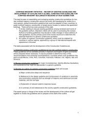
seismic design guide for confined masonry buildings - draft
seismic design guide for confined masonry buildings - draft
seismic design guide for confined masonry buildings - draft

Create successful ePaper yourself
Turn your PDF publications into a flip-book with our unique Google optimized e-Paper software.
SEISMIC DESIGN GUIDE<br />
FOR CONFINED MASONRY BUILDINGS<br />
- DRAFT-<br />
Prepared by<br />
Roberto Meli, Mexico (Co-Chair)<br />
Svetlana Brzev, Canada (Co-Chair)<br />
Maximiliano Astroza, Chile<br />
Teddy Boen, Indonesia<br />
Francisco Crisafulli, Argentina<br />
Junwu Dai, China<br />
Mohammed Farsi, Algeria<br />
Tim Hart, USA<br />
Ahmed Mebarki, France<br />
A.S. Moghadam, Iran<br />
Daniel Quiun, Peru<br />
Miha Tomazevic, Slovenia<br />
Luis Yamin, Colombia<br />
April 2010<br />
Confined Masonry Network<br />
A Project of the World Housing Encyclopedia, EERI & IAEE<br />
With funding support from Risk Management Solutions
Seismic Design Guide <strong>for</strong> Confined Masonry Buildings DRAFT April 2010<br />
Acknowledgments<br />
These <strong>draft</strong> <strong>guide</strong>lines were prepared by a committee of international experts, led by<br />
Roberto Meli of Mexico and Svetlana Brzev of Canada. Other committee members<br />
included: Maximiliano Astroza, Chile; Teddy Boen, Indonesia; Francisco Crisafulli,<br />
Argentina; Junwu Dai, China; Mohammed Farsi, Algeria; Tim Hart, USA; Ahmed<br />
Mebarki, France; A.S. Moghadam, Iran; Daniel Quiun, Peru; Miha Tomazevic, Slovenia;<br />
and Luis Yamin, Colombia.<br />
Particular thanks are due to Leonardo Flores and Miguel Angel Pacheco, research<br />
engineers at the National Centre <strong>for</strong> Disaster Prevention, Mexico City. They were<br />
responsible <strong>for</strong> compiling many of the codes that were reviewed as part of this<br />
project, conducting some of the analyses and preparing the drawings and figures.<br />
The authors would also like to thank Bill McEwen of the Masonry Institute of British<br />
Columbia who reviewed this document and gave very useful comments.<br />
The authors would also like to acknowledge the financial support of Risk Management<br />
Solutions in the early stages of this project, and in particular the enthusiastic support<br />
received from Sahar Safaie. The authors also acknowledge the ongoing support of the<br />
Earthquake Engineering Research Institute and staff member Marjorie Greene.<br />
Special thanks are due the National In<strong>for</strong>mation Centre of Earthquake Engineering at the<br />
Indian Institute of Technology, Kanpur, India, <strong>for</strong> allowing us to incorporate part of one of<br />
their publications on <strong>confined</strong> <strong>masonry</strong>, written by co-chair Svetlana Brzev.<br />
This document is a DRAFT and will be circulated widely <strong>for</strong> review and comment be<strong>for</strong>e<br />
it is released in final <strong>for</strong>m. If you have comments on the DRAFT, please <strong>for</strong>ward them to<br />
Marjorie Greene at mgreene@eeri.org.<br />
2
Seismic Design Guide <strong>for</strong> Confined Masonry Buildings DRAFT April 2010<br />
Table of Contents<br />
1 INTRODUCTION.........................................................................................................................4<br />
1.1 Scope and Objectives ...........................................................................................................................4<br />
1.2 Confined Masonry Buildings: Key Structural Components..............................................................4<br />
1.3 Seismic Response of Confined Masonry Buildings ..........................................................................8<br />
1.3.1 Per<strong>for</strong>mance of <strong>confined</strong> <strong>masonry</strong> <strong>buildings</strong> in past earthquakes...................................................8<br />
1.3.2 General system behavior.................................................................................................................9<br />
2 GENERAL REQUIREMENTS...................................................................................................14<br />
2.1 Design and Per<strong>for</strong>mance Objectives................................................................................................ 14<br />
2.2 Seismic Hazard ................................................................................................................................... 14<br />
2.3 General Planning and Design Aspects ............................................................................................ 15<br />
2.4 Materials .............................................................................................................................................. 17<br />
2.4.1 Units.............................................................................................................................................. 17<br />
2.4.2 Mortar ........................................................................................................................................... 19<br />
2.4.3 Concrete ....................................................................................................................................... 19<br />
2.4.4 Rein<strong>for</strong>cing Steel .......................................................................................................................... 20<br />
2.4.5 Masonry........................................................................................................................................ 20<br />
2.4.6 Testing of Masonry Materials ....................................................................................................... 21<br />
3 GUIDELINES FOR NON-ENGINEERED CONFINED MASONRY BUILDINGS......................22<br />
3.1 Building Components ........................................................................................................................ 22<br />
3.1.1 Masonry Walls .............................................................................................................................. 22<br />
3.1.2 Confining Elements (tie-columns and tie-beams)......................................................................... 27<br />
3.1.3 Additional requirements <strong>for</strong> <strong>buildings</strong> with flexible diaphragms.................................................... 32<br />
3.2 Construction Quality .......................................................................................................................... 33<br />
4 DESIGN OF ENGINEERED CONFINED MASONRY BUILDINGS..........................................33<br />
GUIDELINES FOR SPECIAL INSPECTION OF CONFINED MASONRY CONSTRUCTION ........47<br />
INTRODUCTION..............................................................................................................................47<br />
REFERENCES.................................................................................................................................56<br />
APPENDICES<br />
A Simplified Method <strong>for</strong> Wall Density Calculation in Low-Rise Buildings<br />
B Guidelines <strong>for</strong> Special Inspection of Confined Masonry Construction<br />
3
Seismic Design Guide <strong>for</strong> Confined Masonry Buildings DRAFT April 2010<br />
1 Introduction<br />
1.1 Scope and Objectives<br />
The purpose of this document is to:<br />
• Explain the mechanism of <strong>seismic</strong> response of <strong>confined</strong> <strong>masonry</strong> <strong>buildings</strong> <strong>for</strong> in- and out-ofplane<br />
<strong>seismic</strong> effects and other relevant <strong>seismic</strong> response issues,<br />
• Recommend <strong>design</strong> provisions related to the wall layout and density, and prescribe minimum<br />
size requirements <strong>for</strong> structural components of <strong>confined</strong> <strong>masonry</strong> <strong>buildings</strong> (tie-columns, tiebeams,<br />
walls), rein<strong>for</strong>cement size and detailing in the <strong>for</strong>m of prescriptive provisions <strong>for</strong> low-rise<br />
<strong>buildings</strong> (1- to 2- stories high),<br />
• Recommend rational procedures <strong>for</strong> <strong>seismic</strong> <strong>design</strong> of medium-rise <strong>buildings</strong> up to 4-5 stories<br />
high, and<br />
• Provide a summary of the <strong>seismic</strong> <strong>design</strong> provisions <strong>for</strong> <strong>confined</strong> <strong>masonry</strong> <strong>buildings</strong> from<br />
relevant international codes.<br />
The document is divided into four chapters. Chapter 1 provides an overview of <strong>confined</strong> <strong>masonry</strong><br />
construction and its components. It discusses the <strong>seismic</strong> per<strong>for</strong>mance of <strong>confined</strong> <strong>masonry</strong><br />
<strong>buildings</strong> in past earthquakes, and is based largely on the publication Earthquake-Resistant<br />
Confined Masonry Construction (Brzev, 2008). Chapter 2 presents general requirements related to<br />
<strong>confined</strong> <strong>masonry</strong> construction. Chapter 3 outlines a <strong>guide</strong>line <strong>for</strong> low-rise non-engineered <strong>confined</strong><br />
<strong>masonry</strong> <strong>buildings</strong> (up to two stories high), which could be built without engineered <strong>design</strong><br />
per<strong>for</strong>med by qualified engineers or architects, and thus no <strong>design</strong> calculations or procedures are<br />
included. Many single-family dwellings are built in this manner. Additional <strong>design</strong> procedures and<br />
requirements <strong>for</strong> engineered <strong>confined</strong> <strong>masonry</strong> <strong>buildings</strong> are outlined in Chapter 4. Medium-rise<br />
<strong>buildings</strong> of this type (up to five stories high) can be <strong>design</strong>ed and built following the<br />
recommendations provided in this document and other relevant national codes and standards.<br />
This <strong>guide</strong> will be a useful resource <strong>for</strong> <strong>design</strong> engineers, academics, code development<br />
organizations and non-governmental organizations in countries in which <strong>design</strong> codes and<br />
standards do not contain <strong>seismic</strong> <strong>design</strong> provisions <strong>for</strong> <strong>confined</strong> <strong>masonry</strong> construction. This<br />
document may also be a useful reference <strong>for</strong> <strong>design</strong> engineers and other professionals in the<br />
countries that have codes which address <strong>confined</strong> <strong>masonry</strong> construction.<br />
This document was developed by a group of international experts in earthquake engineering and<br />
<strong>confined</strong> <strong>masonry</strong> construction. The recommendations are based on <strong>design</strong> and construction<br />
experience and research studies from countries and regions where <strong>confined</strong> <strong>masonry</strong> construction<br />
has been practiced <strong>for</strong> many decades, including Mexico, Peru, Chile, Argentina, Iran, Indonesia,<br />
China, Algeria and Slovenia. References to relevant provisions of international standards and<br />
codes have been made in the document.<br />
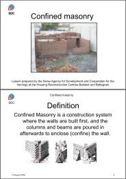
1.2 Confined Masonry Buildings: Key Structural Components<br />
Confined <strong>masonry</strong> construction has evolved through an in<strong>for</strong>mal process based on its satisfactory<br />
per<strong>for</strong>mance in past earthquakes. The first reported use of <strong>confined</strong> <strong>masonry</strong> construction was in<br />
the reconstruction of <strong>buildings</strong> destroyed by the 1908 Messina, Italy earthquake (Magnitude 7.2),<br />
which killed over 70,000 people. Over the last 30 years, <strong>confined</strong> <strong>masonry</strong> construction has been<br />
practiced in Mediterranean Europe (Italy, Slovenia, Serbia), Central and South America (Mexico,<br />
Chile, Peru, Argentina, and other countries), the Middle East (Iran, Algeria, Morocco), South Asia<br />
(Indonesia), and the Far East (China). It is important to note that <strong>confined</strong> <strong>masonry</strong> construction<br />
has been practiced in the countries and regions with extremely high <strong>seismic</strong> risk. Several examples<br />
4
Seismic Design Guide <strong>for</strong> Confined Masonry Buildings DRAFT April 2010<br />
of <strong>confined</strong> <strong>masonry</strong> construction around the world, from Argentina, Chile, Iran, Peru, Serbia and<br />
Slovenia, are featured in the World Housing Encyclopedia (EERI/IAEE, 2000).<br />
Confined <strong>masonry</strong> construction has emerged as a building technology that offers an alternative to<br />
both unrein<strong>for</strong>ced <strong>masonry</strong>, and to rein<strong>for</strong>ced concrete (RC) frame construction with <strong>masonry</strong> infill<br />
walls. In fact, <strong>confined</strong> <strong>masonry</strong> has features of both these technologies. Confined <strong>masonry</strong><br />
construction consists of <strong>masonry</strong> walls (made either of clay brick or concrete block units) and<br />
horizontal and vertical RC confining members built on all four sides of a <strong>masonry</strong> wall panel.<br />
Vertical members, called tie-columns, resemble columns in RC frame construction except that they<br />
tend to be of far smaller cross-sectional dimensions and rein<strong>for</strong>cement ratios; most importantly,<br />
they are built after the <strong>masonry</strong> wall has been completed. Horizontal elements, called tie-beams,<br />
resemble beams in RC frame construction. Alternative terms, horizontal ties and vertical ties, are<br />
sometimes used instead of tie-beams and tie-columns.<br />
The confining members are effective in<br />
• Enhancing the stability and integrity of <strong>masonry</strong> walls <strong>for</strong> in-plane and out-of-plane<br />
earthquake loads. Confining members can effectively contain damaged <strong>masonry</strong> walls, and<br />
ensure adequate connections between the intersecting walls and the wall-to-roof/floor and<br />
wall-to-foundation connections;<br />
• Enhancing the strength (resistance) of <strong>masonry</strong> walls under lateral earthquake loads, and<br />
• Preventing the brittle <strong>seismic</strong> response of <strong>masonry</strong> walls under and thereby improving their<br />
earthquake per<strong>for</strong>mance.<br />
This document addresses <strong>confined</strong> <strong>masonry</strong> construction consisting of <strong>masonry</strong> walls made of solid<br />
clay bricks, hollow clay tiles, or concrete blocks, and “<strong>confined</strong>” with RC tie-beams and tiecolumns.<br />
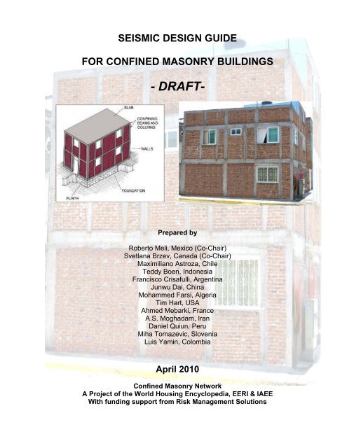
The structural components of a <strong>confined</strong> <strong>masonry</strong> building are shown in Figure 1 and their<br />
respective roles are explained below:<br />
• Masonry walls – transmit the gravity load from the slab(s) above down to the foundation.<br />
The walls act as bracing panels, which resist horizontal earthquake <strong>for</strong>ces. The walls must<br />
be <strong>confined</strong> by concrete tie-beams and tie-columns to ensure satisfactory earthquake<br />
per<strong>for</strong>mance.<br />
• Confining elements (RC tie-columns and tie-beams) – provide restraint to <strong>masonry</strong> walls<br />
and protect them from complete disintegration even in major earthquakes. These elements<br />
have an important role in ensuring vertical stability of a building in an earthquake.<br />
• Floor and roof slabs – transmit both gravity and lateral loads to the walls. In an earthquake,<br />
slabs behave like horizontal beams and are called diaphragms. The slabs are typically<br />
made of rein<strong>for</strong>ced concrete, but light-weight roofs made of timber or light gage steel are<br />
also used.<br />
• Plinth band – transmits the load from the walls down to the foundation. It also protects the<br />
ground floor walls from excessive settlement in soft soil conditions.<br />
• Foundation – transmits the loads from the structure to the ground.<br />
It should be noted that the term “<strong>confined</strong> <strong>masonry</strong>” is used in a general sense <strong>for</strong> different <strong>for</strong>ms of<br />
<strong>masonry</strong> construction rein<strong>for</strong>ced with additional steel, timber, or concrete elements, however these<br />
<strong>for</strong>ms are outside the scope of this document.<br />
5
Seismic Design Guide <strong>for</strong> Confined Masonry Buildings DRAFT April 2010<br />
Figure 1. A typical <strong>confined</strong> <strong>masonry</strong> building (Brzev, 2008).<br />
Confined <strong>masonry</strong> construction is somewhat similar to rein<strong>for</strong>ced <strong>masonry</strong>. In rein<strong>for</strong>ced <strong>masonry</strong>,<br />
vertical and horizontal rein<strong>for</strong>cement bars are provided to enhance the strength of <strong>masonry</strong> walls.<br />
Masonry units are usually hollow and are made of concrete or clay. Vertical rein<strong>for</strong>cement bars are<br />
placed in the hollow cores, which are subsequently grouted with a cement-based grout to anchor<br />
the rein<strong>for</strong>cement and protect it from corrosion. Vertical rein<strong>for</strong>cement is placed at the wall corners<br />
and intersections, around the openings, and at additional locations depending on expected <strong>seismic</strong><br />
loads. Horizontal rein<strong>for</strong>cement is provided in the <strong>for</strong>m of ladder-shaped wire rein<strong>for</strong>cement placed<br />
in horizontal joints or de<strong>for</strong>med rein<strong>for</strong>cement bars placed in bond beams, typically located at floor<br />
and/or lintel levels.<br />
In <strong>confined</strong> <strong>masonry</strong>, the rein<strong>for</strong>cement is concentrated in vertical and horizontal RC confining<br />
elements whereas the <strong>masonry</strong> walls are usually free of rein<strong>for</strong>cement. Figure 2 illustrates the<br />
difference between rein<strong>for</strong>ced and <strong>confined</strong> <strong>masonry</strong> construction (note that both examples use<br />
concrete block construction). Rein<strong>for</strong>ced <strong>masonry</strong> construction requires advanced construction<br />
skills and quality of construction. For example, vertical wall rein<strong>for</strong>cement placed in the hollow<br />
cores in <strong>masonry</strong> blocks must be continuous from the foundation to the roof level, and must match<br />
dowels extended from the foundation. Subsequently, hollow cores (cells) in rein<strong>for</strong>ced <strong>masonry</strong><br />
blocks need to be filled with cement-based grout which needs to have a specific mix proportions <strong>for</strong><br />
placing into relatively small-sized cores. Horizontal rein<strong>for</strong>cement is placed in bond beam blocks<br />
which also need to be grouted using specialized equipment <strong>for</strong> pumping the grouts into <strong>masonry</strong>.<br />
Confined <strong>masonry</strong> is simpler and more <strong>for</strong>giving construction practice, since the use of steel and<br />
concrete is limited to confining elements (vertical tie-columns and horizontal tie-beams). The quality<br />
of construction in confining elements can be checked with more confidence compared to the<br />
installation of rein<strong>for</strong>cement and grout in hollow block cores in rein<strong>for</strong>ced <strong>masonry</strong> construction.<br />
6
Seismic Design Guide <strong>for</strong> Confined Masonry Buildings DRAFT April 2010<br />
a) b)<br />
Figure 2. a) Confined <strong>masonry</strong> construction in Indonesia (Meisl et al, 2006) and b) rein<strong>for</strong>ced<br />
<strong>masonry</strong> construction in Canada (Bill McEwen).<br />
The appearance of a finished <strong>confined</strong> <strong>masonry</strong> construction and a RC frame with <strong>masonry</strong> infills<br />
may look alike, however these two construction systems are substantially different, as illustrated in<br />
Figure 3. The main differences are construction sequence and how these structures resist gravity<br />
and lateral loads. In <strong>confined</strong> <strong>masonry</strong> construction, <strong>masonry</strong> walls are constructed first, followed<br />
by the cast in-place RC tie-columns. Finally, RC tie-beams are constructed on top of the walls,<br />
simultaneously with the floor/roof slab construction. Confining elements are not <strong>design</strong>ed to act as<br />
beams and columns in a moment-resisting frame; as a result, detailing of rein<strong>for</strong>cement is simple.<br />
In general, confining elements have smaller cross-sectional dimensions than the corresponding<br />
beams and columns in a RC frame building. The most important difference between the <strong>confined</strong><br />
<strong>masonry</strong> walls and infill walls is that infill walls are not bearing the gravity loads from the building<br />
floors and roof, while the walls in a <strong>confined</strong> <strong>masonry</strong> building are bearing these gravity loads.<br />
An advantage of <strong>confined</strong> <strong>masonry</strong> construction compared to rein<strong>for</strong>ced <strong>masonry</strong> and RC frames<br />
with <strong>masonry</strong> infills is simpler concrete construction and, detailing of steel rein<strong>for</strong>cement. Due to a<br />
less consumption of steel and cement, construction of a <strong>confined</strong> <strong>masonry</strong> building is expected to<br />
be more economical compared to an otherwise similar rein<strong>for</strong>ced <strong>masonry</strong> or a RC frame building<br />
with <strong>masonry</strong> infills.<br />
7
Seismic Design Guide <strong>for</strong> Confined Masonry Buildings DRAFT April 2010<br />
1<br />
2<br />
1<br />
2<br />
tie-beam<br />
beam<br />
column<br />
Infill wall<br />
tie-column<br />
Load bearing wall<br />
Infill wall<br />
Load bearing wall<br />
a) b)<br />
Figure 3. a) Rein<strong>for</strong>ced concrete frame construction and b) <strong>confined</strong> <strong>masonry</strong> construction.<br />
1.3 Seismic Response of Confined Masonry Buildings<br />
1.3.1 Per<strong>for</strong>mance of <strong>confined</strong> <strong>masonry</strong> <strong>buildings</strong> in past earthquakes<br />
Confined <strong>masonry</strong> <strong>buildings</strong> have shown satisfactory per<strong>for</strong>mance in past earthquakes. In general,<br />
<strong>buildings</strong> of this type do experience some damage in earthquakes, however when properly<br />
<strong>design</strong>ed and constructed they are able to sustain earthquake effects without collapse. Earthquakeinduced<br />
life loss related to <strong>confined</strong> <strong>masonry</strong> <strong>buildings</strong> has been insignificant in counties and<br />
regions where this technology has been practiced, such as Latin America, a region with high<br />
<strong>seismic</strong> risk and frequent high intensity earthquakes. Confined <strong>masonry</strong> <strong>buildings</strong> have per<strong>for</strong>med<br />
very well in past Latin American earthquakes; this particularly applies to <strong>buildings</strong> with regular plan<br />
and elevation and high wall density. In such cases, <strong>confined</strong> <strong>masonry</strong> tends to be quite <strong>for</strong>giving of<br />
minor <strong>design</strong> and construction flaws, as well as material deficiencies. Poor <strong>seismic</strong> per<strong>for</strong>mance<br />
has been noted only when gross construction errors, <strong>design</strong> flaws, or material deficiencies have<br />
been introduced in the building <strong>design</strong> and construction process. Poor per<strong>for</strong>mance is usually<br />
associated with tie-column omissions, discontinuous tie-beams, inadequate diaphragm<br />
connections, and inappropriate structural configuration.<br />
8
Seismic Design Guide <strong>for</strong> Confined Masonry Buildings DRAFT April 2010<br />
The earliest reports describing the earthquake per<strong>for</strong>mance of <strong>confined</strong> <strong>masonry</strong> <strong>buildings</strong> date<br />
back to the 1939 earthquake (magnitude 7.8) in Chile. In Chillán, where a Modified Mercalli<br />
Intensity (MMI) of IX was reported, over 50% of all inspected <strong>confined</strong> <strong>masonry</strong> <strong>buildings</strong> sustained<br />
the earthquake without any damage, whereas around 60% of unrein<strong>for</strong>ced <strong>masonry</strong> <strong>buildings</strong> either<br />
partially or entirely collapsed, resulting in a death toll of 30,000. Following the 1939 earthquake,<br />
<strong>confined</strong> <strong>masonry</strong> was exposed to several significant earthquakes in Chile, including the 1985<br />
Llolleo earthquake (M 7.8) and, more recently, the February 27, 2010 Maule earthquake (M 8.8).<br />
Confined <strong>masonry</strong> <strong>buildings</strong> per<strong>for</strong>med very well in the Maule earthquake. Figure 4a shows a twostory<br />
<strong>confined</strong> <strong>masonry</strong> house in Curepto which remained virtually undamaged, while the adjacent<br />
adobe house has collapsed. A very similar observation was made after the 2007 Pisco, Peru<br />
earthquake (M 8.0), where <strong>confined</strong> <strong>masonry</strong> <strong>buildings</strong> per<strong>for</strong>med very well compared to other<br />
types of <strong>masonry</strong> <strong>buildings</strong> which were badly damaged or collapsed. Figure 4b shows a six-story<br />
<strong>confined</strong> <strong>masonry</strong> building which remained virtually undamaged in the Pisco earthquake, while the<br />
adjacent unrein<strong>for</strong>ced <strong>masonry</strong> building collapsed.<br />
a) b)<br />
Figure 4. Per<strong>for</strong>mance of <strong>confined</strong> <strong>masonry</strong> <strong>buildings</strong> in recent significant earthquakes: a) the 2010<br />
Maule, Chile earthquake (M.O. Moroni Yadlin), and b) the 2007 Pisco, Peru earthquake (M.<br />
Blondet)).<br />
Per<strong>for</strong>mance of <strong>confined</strong> <strong>masonry</strong> <strong>buildings</strong> in past earthquakes in Chile, Peru, Mexico, El<br />
Salvador, Colombia, Indonesia, and Iran, has been well documented; <strong>for</strong> more details see Brzev<br />
(2008). Specific mechanisms of <strong>seismic</strong> response <strong>for</strong> <strong>confined</strong> <strong>masonry</strong> building components are<br />
discussed below.<br />
1.3.2 General system behavior<br />
A <strong>confined</strong> <strong>masonry</strong> building subjected to earthquake ground shaking can be modeled as a vertical<br />
truss, as shown in Figure 4a). Masonry walls act as diagonal struts resisting compression, while<br />
rein<strong>for</strong>ced concrete confining members act in tension and/or compression, depending on the<br />
direction of lateral earthquake <strong>for</strong>ces. The <strong>seismic</strong> per<strong>for</strong>mance of <strong>confined</strong> <strong>masonry</strong> construction<br />
9
Seismic Design Guide <strong>for</strong> Confined Masonry Buildings DRAFT April 2010<br />
depends on several factors, including <strong>seismic</strong> hazard (earthquake intensity at the specific site), soil<br />
conditions, and, more importantly, the quality of building materials and construction. Well built<br />
<strong>confined</strong> <strong>masonry</strong> <strong>buildings</strong> should be able to sustain the effects of major earthquakes without<br />
collapse.<br />
a) b)<br />
Figure 4. Confined <strong>masonry</strong> building: a) vertical truss model (Murty and Jain, 2000), and b) collapse<br />
at the ground floor level (Alcocer et al., 2004).<br />
The <strong>seismic</strong> response of a <strong>confined</strong> <strong>masonry</strong> building and the internal distribution of earthquake<br />
<strong>for</strong>ces will depend on the type of floor and/or roof system.The floor and roof systems are horizontal<br />
elements of the lateral load-resisting system that act as diaphragms. Their primary role is to<br />
transfer earthquake-induced lateral <strong>for</strong>ces throughout the building to the vertical elements that<br />
resist these <strong>for</strong>ces (shear walls in case of <strong>masonry</strong> <strong>buildings</strong>). A diaphragm can be treated as an I-<br />
shaped beam laid in the horizontal plane, where the floor or roof deck functions as the web to resist<br />
the shear <strong>for</strong>ces, while the boundary elements (tie-beams in case of <strong>confined</strong> <strong>masonry</strong> <strong>buildings</strong>)<br />
act as the flanges and resist bending moments. The manner in which the total shear <strong>for</strong>ce is<br />
distributed to the vertical elements (walls) will depend on the wall rigidity relative to the diaphragm<br />
rigidity. For <strong>design</strong> purposes, diaphragms are usually treated either as rigid or flexible. Cast inplace<br />
concrete or composite <strong>masonry</strong> and concrete floor systems are usually considered as rigid<br />
diaphragms, while timber or light gage steel diaphragms are generally considered as flexible<br />
diaphragms (unless bracing is provided in the plane of the diaphragm).<br />
In <strong>buildings</strong> with rigid diaphragms, shear <strong>for</strong>ces in the walls are distributed in direct proportion to<br />
their rigidity (relative to the rigidity of other walls laid in the same direction). Torsional effects need<br />
to be considered; this may cause an increase of <strong>seismic</strong> <strong>for</strong>ces in some of the walls. Buildings with<br />
rigid diaphragms are very common in most countries where <strong>confined</strong> <strong>masonry</strong> has been practiced<br />
to date.<br />
In <strong>buildings</strong> with flexible diaphragms, the distribution of shear <strong>for</strong>ces to walls is independent of their<br />
relative rigidity. These diaphragms act like a series of simple beams spanning between the walls. A<br />
flexible diaphragm must have adequate strength to transfer the shear <strong>for</strong>ces to the walls, but<br />
cannot distribute torsional <strong>for</strong>ces to the walls in the direction perpendicular to the earthquake<br />
ground motion. Flexible diaphragms are not common in <strong>confined</strong> <strong>masonry</strong> <strong>buildings</strong>, with the<br />
exception of Indonesia and a few other countries, where timber trusses have been routinely used<br />
<strong>for</strong> the roof construction (see Figure 8). Seismic response of <strong>confined</strong> <strong>masonry</strong> <strong>buildings</strong> with<br />
flexible diaphragms and the key factors influencing the response were studied by Hart, Canney,<br />
Huey, and Nixon (2010).<br />
10
Seismic Design Guide <strong>for</strong> Confined Masonry Buildings DRAFT April 2010<br />
In multi-storey <strong>confined</strong> <strong>masonry</strong> <strong>buildings</strong>, earthquake-induced lateral <strong>for</strong>ces are concentrated at<br />
the ground floor level, thus causing significant shear cracking. Under severe earthquake ground<br />
shaking, the collapse of <strong>confined</strong> <strong>masonry</strong> <strong>buildings</strong> may take place due to a soft storey effect that<br />
is similar to RC frames with <strong>masonry</strong> infills (see Figure 4b). This behavior was confirmed by<br />
experimental studies (Alcocer et al., 2004, 2004a). After the 2003 Tecomán, Mexico earthquake, a<br />
three-storey <strong>confined</strong> <strong>masonry</strong> apartment building in Colima experienced significant damage at the<br />
ground floor level (EERI, 2006). Similar <strong>seismic</strong> response of multi-storey <strong>confined</strong> <strong>masonry</strong><br />
<strong>buildings</strong> was observed after the 2008 Sichuan, China earthquake.<br />
Seismic shaking in a direction perpendicular to the wall causes out-of-plane <strong>for</strong>ces that result in<br />
bending and shear stresses and may, ultimately, cause cracking and possible overturning of the<br />
wall. The out-of-plane <strong>seismic</strong> effects on the walls are more pronounced at higher floor levels (due<br />
to larger accelerations) than in the lower portions of the building, as shown in Figure 5. The extent<br />
of damage and a likelihood of wall collapse will strongly depend on the type of roof and floor<br />
diaphragm (rigid or flexible).<br />
Figure 5. Out-of-plane vibration of walls (Tomazevic, 1999).<br />
1.3.2 Failure mechanisms<br />
A <strong>confined</strong> <strong>masonry</strong> wall subjected to lateral earthquake loading develops either shear or flexural<br />
failure mechanism (Tomazevic and Klemenc, 1997; Tomazevic, 1999; Yoshimura et al. 2004). A<br />
shear failure mechanism develops due to in-plane <strong>seismic</strong> loads (acting in the wall plane), while a<br />
flexural failure mechanism can develop either due to in-plane or out-of-plane loads (acting<br />
perpendicular to the wall plane).<br />
The in-plane shear failure mechanism is characterized by distributed diagonal cracking in the wall,<br />
and either by the bond destruction at the mortar-brick interface (shear-friction mechanism), or a<br />
tensile cracking of the bricks. Initially, a <strong>masonry</strong> wall panel resists the effects of lateral earthquake<br />
loads while the tie-columns do not play a significant role. However, once the cracking takes place,<br />
the wall pushes the tie-columns sideways. At that stage, the vertical rein<strong>for</strong>cement in the tiecolumns<br />
becomes engaged in resisting tension and compression stresses (Tomazevic and<br />
Klemenc, 1997). Damage in the tie-columns at the ultimate load level is concentrated at the top and<br />
bottom of the panel. Shear failure can lead to severe damage in the <strong>masonry</strong> wall and at the top<br />
and bottom of the tie-columns, as shown in Figure 6.<br />
11
Seismic Design Guide <strong>for</strong> Confined Masonry Buildings DRAFT April 2010<br />
Figure 6. Shear failure of <strong>confined</strong> <strong>masonry</strong> walls (Yoshimura et al., 2004 – left; Aguilar and<br />
Alcocer, 2001 – right).<br />
In-plane shear damage of <strong>confined</strong> <strong>masonry</strong> walls is the most common damage pattern found in<br />
<strong>confined</strong> <strong>masonry</strong> <strong>buildings</strong> in past earthquakes, e.g. the 1999 Tehuacán and the 2003 Tecomán,<br />
Mexico earthquake, the 2001 San Salvador, El Salvador earthquake, and the 2010 Maule, Chile<br />
earthquake, as shown in Figure 7. Note that Figure 7a shows damage in Cauquenes, the city with<br />
the highest MKS intensity of 8.0 located close to the Maule earthquake epicenter. It is not certain<br />
whether the building shown in Figure 7a was <strong>design</strong>ed following the provisions <strong>for</strong> <strong>confined</strong><br />
<strong>masonry</strong> <strong>buildings</strong> contained in the Chilean code NCh2123.<br />
a) b)<br />
Figure 7. In-plane shear failure of poorly <strong>confined</strong> <strong>masonry</strong> construction: a) the 2010 Maule, Chile<br />
earthquake (M. Astroza), and b) the 2001 El Salvador earthquake (EERI, 2001).<br />
Out-of-plane shear failure of <strong>confined</strong> <strong>masonry</strong> walls has been observed almost exclusively in<br />
<strong>confined</strong> <strong>masonry</strong> <strong>buildings</strong> with flexible roof/floor diaphragms. The mechanism <strong>for</strong> out-of-plane<br />
response is displacement-controlled and can be explained either by an arching mechanism, or by<br />
the overturning of an entire wall due to inadequate wall anchorage to adjacent tie-beams and/or tiecolumns<br />
(refer to Section 3.1.3 <strong>for</strong> more details). Damage due to the out-of-plane <strong>seismic</strong> effects<br />
was observed in some Indonesian earthquakes (e.g. 2007 West Sumatra earthquake).<br />
12
Seismic Design Guide <strong>for</strong> Confined Masonry Buildings DRAFT April 2010<br />
Figure 8. Out-of-plane collapse of <strong>confined</strong> <strong>masonry</strong> walls in the 2007 West Sumatra earthquake<br />
(Build Change).<br />
Flexural failure due to in-plane lateral loads, and it is characterized by horizontal cracking of the<br />
mortar bed joints located on the tension side of the wall, as shown in Figure 9 (Yoshimura et al.<br />
2004). Separation of the tie-columns from the wall was observed in some cases when a toothed<br />
wall-to-column connection was absent, and there were no connecting ties between the tie-column<br />
and the wall. Extensive horizontal cracking in tie-columns and shear cracking in the walls can be<br />
observed in Figure 9.<br />
Figure 9. Flexural failure of <strong>confined</strong> <strong>masonry</strong> walls (Yoshimura et al., 2004).<br />
Experimental studies have shown that tie-columns have key role in resisting the gravity loads in<br />
damaged <strong>confined</strong> <strong>masonry</strong> <strong>buildings</strong>, and in ensuring their vertical stability (Alcocer, 2006). Due to<br />
their high axial stiffness and tension/compression load resistance, tie-columns resist a major<br />
portion of gravity load after the walls experience severe damage. The failure of a tie-column usually<br />
takes place when cracks propagate from the <strong>masonry</strong> wall into the tie-column and shear it off,<br />
thereby compromising the wall ability to resist gravity loads. It has been observed that the amount<br />
of ties at the tie-beam-to-tie-column joint, and the development length of the longitudinal<br />
rein<strong>for</strong>cement also appear to play a role in the tie-column shear resistance.<br />
13
Seismic Design Guide <strong>for</strong> Confined Masonry Buildings DRAFT April 2010<br />
2 General Requirements<br />
2.1 Design and Per<strong>for</strong>mance Objectives<br />
Seismic provisions of most modern building codes are based on the “life safety” per<strong>for</strong>mance<br />
objective: extensive structural damage is acceptable in a severe earthquake, but a collapse should<br />
be avoided so the occupants can safely evacuate the building. The recommendations in this<br />
<strong>guide</strong>line are based on this life safety per<strong>for</strong>mance objective.<br />
Properly <strong>design</strong>ed and constructed <strong>confined</strong> <strong>masonry</strong> <strong>buildings</strong> with sufficient wall density are not<br />
expected to experience damage due to moderate earthquakes.<br />
2.2 Seismic Hazard<br />
Seismicity levels in this document are based on the global <strong>seismic</strong> hazard map developed by the<br />
Global Seismic Hazard Program (GSHAP) shown in Figure 10. Peak ground acceleration (PGA) is<br />
defined <strong>for</strong> hard soil conditions at various global localities. Note that the acceleration at a specific<br />
site depends on the type of soil. The GSHAP <strong>seismic</strong> hazard levels used in this document are<br />
summarized in Table 1. This in<strong>for</strong>mation can be used in the absence of country or region-specific<br />
<strong>seismic</strong> hazard in<strong>for</strong>mation provided by the national codes or seismological studies.<br />
Table 1. GSHAP Seismic Hazard Levels<br />
Seismic PGA (m/sec 2 )<br />
PGA (g)<br />
Hazard Level<br />
Low PGA≤0.8 m/sec 2 PGA≤0.08g<br />
Moderate 0.8 m/sec 2
Seismic Design Guide <strong>for</strong> Confined Masonry Buildings DRAFT April 2010<br />
2.3 General Planning and Design Aspects<br />
Experience from past earthquakes has confirmed that the conceptual <strong>design</strong> of a building is critical<br />
to its satisfactory per<strong>for</strong>mance. Architects play an important role in developing conceptual <strong>design</strong><br />
which defines the overall shape, size and dimensions of a building. Structural engineers are<br />
responsible <strong>for</strong> analyzing structural safety, and must work closely with architects to ensure that the<br />
<strong>design</strong> meets both structural and architectural requirements. Engineers are often not involved in<br />
<strong>design</strong> of low-rise <strong>buildings</strong> such as the <strong>confined</strong> <strong>masonry</strong> <strong>buildings</strong> discussed in this document.<br />
When architects are involved, they work directly with contractors throughout the construction<br />
process. There<strong>for</strong>e, it is critical <strong>for</strong> architects and builders to follow simple rules <strong>for</strong> the <strong>design</strong> and<br />
construction of <strong>confined</strong> <strong>masonry</strong> <strong>buildings</strong>.<br />
A regular building layout is one of the key requirements <strong>for</strong> satisfactory earthquake per<strong>for</strong>mance.<br />
Desirable and undesirable solutions are shown below. The material in this section is largely based<br />
on the publications by Blondet (2005) and Brzev (2008).<br />
1) The building plan should be of a regular shape (see Figure 11).<br />
No<br />
Yes<br />
Irregular<br />
Regular<br />
Figure 11. Regular building plan.<br />
2) The building should not be excessively long. Ideally, the length-to-width ratio should not exceed<br />
4 (see Figure 12).<br />
No<br />
Yes<br />
Width<br />
More than 4 times the width<br />
Width<br />
Less than 4<br />
times the width<br />
Figure 12. Building length-to-width aspect ratio.<br />
15
Seismic Design Guide <strong>for</strong> Confined Masonry Buildings DRAFT April 2010<br />
3) The walls should be built in a symmetrical manner to minimize torsional effects. Note that it is<br />
not always possible to have a perfectly symmetrical wall layout – the one shown on the right in<br />
Figure 13 is not ideal, but is much better than the layout shown on the left.<br />
No<br />
Yes<br />
Figure 13. Wall layout.<br />
4) Since the earthquake per<strong>for</strong>mance of <strong>confined</strong> <strong>masonry</strong> <strong>buildings</strong> largely depends on the shear<br />
resistance of <strong>masonry</strong> walls, it is essential that sufficient number and total length of walls are<br />
provided in each direction. Figure 14 (left) shows building plans with inadequate wall<br />
distribution. To avoid twisting (torsion) of the building in an earthquake, the walls should be<br />
placed as far apart as possible, preferably at the exterior of the building, as shown in Figure 14<br />
(right).<br />
No<br />
Yes<br />
Figure 14. Wall distribution: plan view.<br />
16
Seismic Design Guide <strong>for</strong> Confined Masonry Buildings DRAFT April 2010<br />
5) The walls should be continuous over the height of the building. Figure 15 (left) shows walls<br />
which are offset along the building height, while Figure 15 (right) shows continuous walls.<br />
No<br />
Yes<br />
Discontinuous walls<br />
Continuous walls<br />
Figure 15. Continuity of walls along the building height.<br />
6) Openings (doors and windows) should be placed in the same position over the height of the<br />
building, as illustrated in Figure 16.<br />
No<br />
Yes<br />
Inadequate location of window<br />
and door openings<br />
Adequate location of openings<br />
with tie-beams and tie-colums<br />
around openings<br />
Figure 16. Location of openings in a building.<br />
2.4 Materials<br />
2.4.1 Units<br />
2.4.1.1 Types of units<br />
The following types of <strong>masonry</strong> units are acceptable <strong>for</strong> the <strong>confined</strong> <strong>masonry</strong> construction:<br />
1) Solid concrete blocks,<br />
2) Hollow concrete blocks,<br />
3) Solid clay bricks, and<br />
4) Hollow clay tiles (blocks).<br />
The hollow units referred to in this document are those having, in their most unfavorable cross<br />
section, a net area at least 50% the gross area, and an exterior face shells shall thickness of not<br />
less than 15 mm (see Figure 17a). For hollow units with two to four cells, the minimum thickness of<br />
the interior webs is 13 mm. Multi-per<strong>for</strong>ated units are those with more than seven per<strong>for</strong>ations or<br />
17
Seismic Design Guide <strong>for</strong> Confined Masonry Buildings DRAFT April 2010<br />
cells (see Figure 17b). For multi-per<strong>for</strong>ated units having per<strong>for</strong>ations of the same dimensions and<br />
distribution, the minimum thickness of the interior webs is 7 mm.<br />
Solid <strong>masonry</strong> units can have per<strong>for</strong>ations, however the ratio of net to gross area should be greater<br />
than 75%.<br />
Hollow <strong>masonry</strong> units should be used with caution in non-engineered <strong>buildings</strong>. It is critical <strong>for</strong> their<br />
satisfactory <strong>seismic</strong> per<strong>for</strong>mance to ensure that the minimum material strength and construction<br />
quality recommendations outlined in this document have been met.<br />
The following types of units are not recommended <strong>for</strong> <strong>confined</strong> <strong>masonry</strong> construction:<br />
1) Masonry units with horizontal per<strong>for</strong>ations, and<br />
2) Natural stone <strong>masonry</strong> and adobe (sun-dried earthen units).<br />
exterior face shell<br />
thickness ≥ 15 mm<br />
web thickness ≥ 13 mm<br />
gross area<br />
unit height<br />
thickness of<br />
unit<br />
length of<br />
unit<br />
a) Hollow units<br />
cell<br />
net area<br />
net area<br />
≥ 0.5<br />
gross area<br />
per<strong>for</strong>ation<br />
thickness<br />
≥ 15 mm<br />
thickness<br />
≥ 7 mm<br />
b) Example of multi-per<strong>for</strong>ated units<br />
Figure 17. Masonry units: types and dimensions (NTC-M, 2004).<br />
18
Seismic Design Guide <strong>for</strong> Confined Masonry Buildings DRAFT April 2010<br />
2.4.1.2 Compressive strength<br />
Minimum compressive strength values <strong>for</strong> various <strong>masonry</strong> units (f p *) based on their gross area are<br />
summarized in Table 2.<br />
Table 2. Minimum compressive strength (f p *) <strong>for</strong> <strong>masonry</strong> units<br />
Type of <strong>masonry</strong> unit<br />
Minimum compressive<br />
strength (f p *)<br />
MPa (kg/cm 2 )<br />
Solid concrete blocks 5 (50)<br />
Hollow concrete blocks 5 (50)<br />
Hand-made clay bricks 4 (40)<br />
Machine-made clay bricks 10 (100)<br />
Hollow clay units 10 (100)<br />
Multi-per<strong>for</strong>ated clay bricks 10 (100)<br />
2.4.2 Mortar<br />
a) Three different types of mortar (I, II and III) can be used <strong>for</strong> <strong>confined</strong> <strong>masonry</strong> construction,<br />
as outlined in Table 3.<br />
Table 3. Mortar mix proportions and compressive strength (f j *) (NTC-M, 2004)<br />
Type of<br />
mortar<br />
I<br />
II<br />
Hydraulic<br />
cement<br />
Masonry<br />
cement<br />
Hydrated<br />
lime<br />
1 - 0 to ¼<br />
1 0 to ½<br />
1 - ¼ to ½<br />
1 ½ to 1<br />
III 1 - ½ to 1<br />
Sand<br />
Not less than 2.25, nor<br />
more than 3 times the<br />
total of cementitius<br />
materials in volume<br />
Nominal<br />
compressive strength<br />
(f j *)<br />
MPa (kg/cm 2 )<br />
12.5 (125)<br />
7.5 (75)<br />
4.0 (40)<br />
2.4.3 Concrete<br />
A minimum concrete compressive strength of 15 MPa based on cylinder testing is recommended.<br />
The concrete mix should provide the high workability required <strong>for</strong> casting the small sections of the<br />
RC confining members.<br />
19
Seismic Design Guide <strong>for</strong> Confined Masonry Buildings DRAFT April 2010<br />
2.4.4 Rein<strong>for</strong>cing Steel<br />
For longitudinal rein<strong>for</strong>cement, the use of de<strong>for</strong>med steel with a nominal yield strength of 400 MPa<br />
and the ultimate elongation of 9% (ductile steel) is recommended. When steel with a yield strength<br />
different than 400 MPa is used, rein<strong>for</strong>cement area should be modified accordingly (increased or<br />
decreased).<br />
Ties <strong>for</strong> tie-beams and tie-column should be made using either mild or de<strong>for</strong>med steel bars.<br />
2.4.5 Masonry<br />
2.4.5.1 Compressive strength<br />
Compressive strength is a very important property of <strong>masonry</strong>, and it is highly variable depending<br />
on local materials and construction practices. The <strong>design</strong> compressive strength (f m *) should ideally<br />
be determined by testing prism specimens made of the <strong>masonry</strong> units and mortar used at the<br />
construction site, as shown in Figure 18a. The prisms should be tested using same procedures as<br />
other <strong>masonry</strong> wall applications (e.g. refer to Section 2.8.1 of NTC-M,2004).<br />
In the absence of testing data, recommended empirical values <strong>for</strong> the <strong>design</strong> compressive strength<br />
of <strong>masonry</strong> (f m *) are provided in Table 4.<br />
Table 4. Design compressive strength of <strong>masonry</strong> (f m *), based on gross cross-sectional area<br />
(NTC-M, 2004)<br />
Type of <strong>masonry</strong> unit<br />
Design compressive strength (f m *)<br />
MPa (kg/cm 2 )<br />
Type of Mortar<br />
I II III<br />
Solid clay bricks 1.5 (15) 1.5 (15) 1.5 (15)<br />
Hollow clay units 4.0 (40) 4.0 (40) 3.0 (30)<br />
Hollow concrete blocks 2.0 (20) 1.5 (15) 1.0 (10)<br />
Solid concrete blocks 2.0 (20) 1.5 (15) 1.5 (15)<br />
2.4.5.2 Basic shear strength<br />
Basic shear strength can be determined by diagonal compression testing of wall specimens, as<br />
shown in Figure 18b. The specimens should be made of the same <strong>masonry</strong> units and mortar as<br />
used <strong>for</strong> the construction. The specimens shall be subjected to monotonic compression load acting<br />
along their diagonal. For more details of the testing procedure, refer to Section 2.8.2 of NTC-M<br />
(2004).<br />
20
Seismic Design Guide <strong>for</strong> Confined Masonry Buildings DRAFT April 2010<br />
load<br />
load<br />
H<br />
<strong>masonry</strong><br />
units<br />
mortar<br />
load<br />
thickness<br />
H<br />
load<br />
a) b)<br />
L<br />
H ≅ L<br />
Figure 18. Masonry testing specimens: a) compressive strength; b) shear strength.<br />
In the absence of test data, recommended empirical values <strong>for</strong> the basic shear strength of <strong>masonry</strong><br />
(v m *) are shown in Table 5.<br />
Table 5. Basic shear strength of <strong>masonry</strong> (v m *) (NTC-M, 2004)<br />
Type of <strong>masonry</strong> unit<br />
Type of mortar<br />
Basic shear<br />
strength (v m *)<br />
MPa (kg/cm 2 )<br />
Solid clay bricks<br />
Hollow clay units<br />
Hollow concrete<br />
blocks<br />
Solid concrete blocks<br />
I 0.35 (3.5)<br />
II and III 0.30 (3.0)<br />
I 0.30 (3.0)<br />
II and III 0.20 (2.0)<br />
I 0.35 (3.5)<br />
II and III 0.25 (2.5)<br />
I 0.30 (3.0)<br />
II and III 0.20 (2.0)<br />
2.4.6 Testing of Masonry Materials<br />
Masonry material testing should be per<strong>for</strong>med whenever possible. The test results need to confirm<br />
that the <strong>masonry</strong> units and mortar meet the minimum requirements of this document. It is expected<br />
that testing procedures <strong>for</strong> <strong>masonry</strong> materials are included in the national standards. In the<br />
absence of such standards, the procedures specified in one of the established codes can be<br />
followed, such as the Technical Norms <strong>for</strong> Design and Construction of Masonry Structures, Mexico<br />
City (NTC-M, 2004).<br />
21
Seismic Design Guide <strong>for</strong> Confined Masonry Buildings DRAFT April 2010<br />
3 Guidelines <strong>for</strong> Non-Engineered Confined Masonry Buildings<br />
This chapter outlines recommendations <strong>for</strong> low-rise non-engineered <strong>confined</strong> <strong>masonry</strong> <strong>buildings</strong><br />
with the maximum height of two stories. These <strong>buildings</strong> are usually built without <strong>design</strong><br />
calculations or specified procedures from qualified engineers. In addition to the recommendations<br />
presented in this chapter, most of the recommendations outlined in Chapter 2 apply to nonengineered<br />
<strong>buildings</strong>. The quality of building materials (<strong>masonry</strong>, concrete, steel) must be verified<br />
<strong>for</strong> non-engineered <strong>buildings</strong>.<br />
3.1 Building Components<br />
3.1.1 Masonry Walls<br />
3.1.1.1 Wall density requirements<br />
Wall density is one of the key parameters influencing the <strong>seismic</strong> per<strong>for</strong>mance of <strong>confined</strong> <strong>masonry</strong><br />
<strong>buildings</strong>. Evidence from past earthquakes shows that <strong>confined</strong> <strong>masonry</strong> <strong>buildings</strong> that had an<br />
adequate wall density were able to resist the effects of major earthquakes without collapse.<br />
The wall density index, d, is equal to<br />
d = A W /A P<br />
where<br />
A W is equal to the cross-sectional area of all walls in one direction, that is, a product of the wall<br />
length and thickness (it is not necessary to deduct the area of tie-columns).<br />
A P is the building floor plan area, as shown in Figure 19.<br />
Ap<br />
Aw<br />
Seismic <strong>for</strong>ce<br />
Figure 19. Wall density index: parameters.<br />
The minimum wall density index required <strong>for</strong> a given building can be determined by applying the<br />
Simplified Method outlined in Appendix A of this document. In the absence of detailed <strong>design</strong><br />
calculations, minimum recommended values <strong>for</strong> wall density index are summarized in Table 6.<br />
These values can be used <strong>for</strong> “simple <strong>buildings</strong>” complying with the following requirements:<br />
1. General requirements:<br />
a. nearly symmetric wall layout in both orthogonal directions over the building height<br />
22
Seismic Design Guide <strong>for</strong> Confined Masonry Buildings DRAFT April 2010<br />
b. exterior walls extend at least 50% of the length of each end of the building plan at each<br />
story.<br />
c. at least 75% of the building weight is supported by the <strong>confined</strong> <strong>masonry</strong> walls<br />
2. Building dimensions (see Figure 20):<br />
a. total building height not greater than 6 m<br />
b. ratio of total building height to the minimum plan width not greater than 1.5<br />
c. ratio of length to width of the building plan not greater than 2.0<br />
3. Floors and roofs:<br />
a. rigid diaphragms (equivalent to a minimum 100 mm thick solid concrete slab)<br />
b. uni<strong>for</strong>m building plans (equal area) over the building height<br />
4. Confined <strong>masonry</strong> walls (see Figure 20):<br />
a. <strong>masonry</strong> properties complying with the minimum requirements specified in Chapter 2 of<br />
this document<br />
b. walls <strong>confined</strong> with tie-columns and tie-beams on all four sides<br />
c. walls to be continuous over the building height and connected to the floors/roof<br />
d. all <strong>masonry</strong> walls to be built using the same materials and properties<br />
w1<br />
W<br />
w2<br />
l1 l2 l3 l4<br />
L<br />
l1 + l2 + l3 + l4 ≥ 0.5L w1 + w2 ≥ 0.5W<br />
H ≤ 6 m<br />
H / W ≥ 1.5<br />
L / W ≤ 2<br />
H<br />
L<br />
W<br />
Figure 20. Requirements <strong>for</strong> “simple <strong>buildings</strong>”.<br />
23
Seismic Design Guide <strong>for</strong> Confined Masonry Buildings DRAFT April 2010<br />
Minimum required wall density index <strong>for</strong> gravity loads can be determined by applying the Simplified<br />
Method outlined in Appendix A. For “simple <strong>buildings</strong>” complying with the above specified<br />
requirements, safety <strong>for</strong> <strong>seismic</strong> and gravity loads can be ensured by using wall density index<br />
values recommended in Table 6. Note that the wall density values presented in Table 6 are more<br />
conservative than the values obtained by <strong>design</strong> calculations using the Simplified Method.<br />
Table 6. Minimum Required Wall Density Index d (%) <strong>for</strong> Each Direction of the Building Plan<br />
Number<br />
Seismic Hazard 1<br />
of stories<br />
n<br />
Low<br />
(PGA ≤ 0.08g)<br />
Moderate<br />
(PGA ≤ 0.25g)<br />
High<br />
(PGA ≤ 0.4g)<br />
Soil Type A B and C A B and C<br />
Solid clay bricks 2 (mortar type I, II and III 3 )<br />
Solid concrete blocks (mortar type I)<br />
1 1.0 1.0 1.0 1.5 2.5<br />
2 1.5 1.5 2.0 3.0 4.5<br />
Solid concrete blocks (mortar type II and III)<br />
Hollow concrete blocks (mortar type I)<br />
Hollow clay units (mortar type I)<br />
1 1.0 1.0 2.0 2.0 3.5<br />
2 1.5 1.5 3.5 4.0 6.5<br />
Hollow concrete blocks or hollow clay units (mortar type II and III)<br />
1 1.0 1.5 2.5 3.0 5.0<br />
2 2.0 3.0 5.0 6.0 9.5<br />
Notes:<br />
1 - see Section 2.2 <strong>for</strong> details on <strong>seismic</strong> hazard levels<br />
2 - see Section 2.4.1 <strong>for</strong> requirements related to <strong>masonry</strong> units<br />
3 - see Section 2.4.2 <strong>for</strong> mortar type in<strong>for</strong>mation<br />
Soil Type:<br />
A Rock or firm soil<br />
B Compact granular soil<br />
C Soft clay soil<br />
3.1.1.2 Wall Spacing<br />
Maximum spacing of transverse walls in <strong>buildings</strong> with flexible diaphragms should not exceed<br />
• 6 m <strong>for</strong> regions of low and moderate <strong>seismic</strong>ity, and<br />
• 4.5 m <strong>for</strong> regions of high and very high <strong>seismic</strong>ity<br />
3.1.1.3 Wall dimensions and height/thickness ratio restrictions<br />
• A minimum wall thickness (t) of 120 mm is required.<br />
• The maximum wall height/thickness (H/t) ratio <strong>for</strong> walls in one to two-story <strong>buildings</strong> must<br />
not exceed 25.<br />
24
Seismic Design Guide <strong>for</strong> Confined Masonry Buildings DRAFT April 2010<br />
3.1.1.4 Parapets and gable walls<br />
Parapets<br />
Tie-columns and tie-beams should extend to the top of the parapet, as shown in Figure 24. If a<br />
parapet is not <strong>confined</strong>, the height should not exceed 0.5 m, otherwise the height limit is 1.2 m.<br />
Gable walls<br />
It is recommended that the top of gable be <strong>confined</strong> with tie-beams and that the tie-columns located<br />
at the middle of the gable wall be extended (whenever applicable), as shown in Figure 21 a.<br />
Special attention should be paid to the concrete construction, and also the gable <strong>masonry</strong><br />
construction since the bricks need to be cut to match the roof slope. Alternatively, a gable portion<br />
of the wall can either be made out of timber or other light-weight material (see Figure 21 b), or tiebeam<br />
depth at the roof level can be increased.<br />
gable<br />
confinement<br />
tie-beam<br />
tie-column<br />
roof<br />
gable<br />
confinement<br />
light weight<br />
gable panel<br />
tie-beam<br />
tie-column<br />
roof<br />
a)<br />
b)<br />
Figure 21. Gable walls: a) rein<strong>for</strong>ced concrete confining elements; b) light-weight gable panel.<br />
3.1.1.4 Walls with openings<br />
A wall that is not completely <strong>confined</strong> on all four sides of the panel should not be considered in wall<br />
density calculations in Section 3.1.1.1, and its contribution to <strong>seismic</strong> resistance of the building<br />
should be disregarded.<br />
A solid wall panel has a total opening area of less than 10% of the panel surface area, provided<br />
that the opening(s) are located outside the diagonals. Alternatively, the wall should be treated as<br />
per<strong>for</strong>ated, that is, the openings should be considered in the <strong>design</strong>. Examples of solid and<br />
per<strong>for</strong>ated walls are shown in Figure 22.<br />
25
Seismic Design Guide <strong>for</strong> Confined Masonry Buildings DRAFT April 2010<br />
Yes<br />
A<br />
No<br />
A<br />
h<br />
h<br />
L<br />
A < 0.1 L x h<br />
a)<br />
L<br />
A < 0.1 L x h<br />
b)<br />
Figure 22. Walls with openings: a) solid wall (openings can be neglected); b) per<strong>for</strong>ated wall<br />
(openings must be considered).<br />
3.1.1.5 Toothing at the wall-to-tie-column interface<br />
It is a good construction practice to provide toothing at the wall-to-tie-column interface. Toothing is<br />
required <strong>for</strong> low-strength <strong>masonry</strong> built using hand-made clay bricks and solid concrete blocks.<br />
Toothed edges should be left on each side of the wall. Toothing length equal to ¼ brick length or<br />
50 mm is recommended (NT E.070, 2006; Blondet, 2005), as shown in Figure 23 a. In some cases<br />
it may be challenging to construct the toothed interface, as shown in Figure 23 b. Horizontal<br />
rein<strong>for</strong>cement anchored into tie-columns, also known as dowels, can be used as an alternative to<br />
toothing, however it is believed that dowels are not necessary <strong>for</strong> low-rise <strong>buildings</strong> (up to two<br />
stories high).<br />
26
Seismic Design Guide <strong>for</strong> Confined Masonry Buildings DRAFT April 2010<br />
Leave toothed edges at the sides<br />
of the wall next to every tie-column<br />
to provide adequate confinement <strong>for</strong><br />
the wall<br />
5 cm<br />
2.5 cm<br />
3 cm<br />
2.5 cm<br />
Machine-made<br />
hollow units<br />
Details of the<br />
toothed<br />
wall edges<br />
(a)<br />
Hand-made<br />
solid units<br />
(b)<br />
Figure 23. Toothing in <strong>confined</strong> <strong>masonry</strong> walls: a) recommended construction practice;<br />
b) undesirable construction practice (SENCICO, 2008).<br />
3.1.2 Confining Elements (tie-columns and tie-beams)<br />
3.1.2.1 Spacing<br />
Tie-columns<br />
Tie-columns should be provided at the following locations:<br />
• at wall intersections, and<br />
• at wall ends.<br />
Tie-columns can also be provided at openings. When tie-columns are provided at openings,<br />
adjacent <strong>confined</strong> <strong>masonry</strong> wall panels enclosed by tie-columns at the ends can be considered in<br />
wall density calculations.<br />
27
Seismic Design Guide <strong>for</strong> Confined Masonry Buildings DRAFT April 2010<br />
Spacing of tie-columns should not exceed:<br />
• 4.5 m <strong>for</strong> high <strong>seismic</strong>ity regions<br />
• 6 m <strong>for</strong> moderate and low <strong>seismic</strong>ity regions.<br />
Tie-beams<br />
A rein<strong>for</strong>ced concrete tie-beam must be provided at the top of each wall. Seismic bands below and<br />
above openings (at lintel/sill level) are not required.<br />
The location and spacing of confining members are illustrated in Figures 24 and 25.<br />
tie-beam in<br />
parapets ≥ 500 mm<br />
tie-beam<br />
spacing<br />
slab<br />
tie-columns<br />
in parapets<br />
t<br />
H<br />
H / t ≤ 25<br />
t ≥ 120 mm<br />
Tie-column<br />
spacing:<br />
6.0 m (moderate <strong>seismic</strong>ity)<br />
4.5 m (high <strong>seismic</strong>ity)<br />
Tie-columns at<br />
wall intersections<br />
confining elements<br />
around openings<br />
Figure 24. Key recommendations <strong>for</strong> non-engineered <strong>confined</strong> <strong>masonry</strong> <strong>buildings</strong> (NTC-M, 2004).<br />
tie-column<br />
spacing ≤ 4 m<br />
thickness ≥ 120 mm<br />
tie-columns at<br />
wall ends and<br />
intersections<br />
tie-columns<br />
at openings<br />
window<br />
door<br />
door<br />
Figure 25. Typical floor plan illustrating the placement of tie-columns (Brzev, 2008).<br />
3.1.2.2 Minimum dimensions<br />
• Tie-column size: 15 cm x t (minimum dimension t x t, where t denotes the wall thickness)<br />
• Tie-beam size: same as tie-column size<br />
The tie-column size should be determined by <strong>design</strong> calculations <strong>for</strong> <strong>buildings</strong> which are more than<br />
two stories high.<br />
28
Seismic Design Guide <strong>for</strong> Confined Masonry Buildings DRAFT April 2010<br />
3.1.2.3 Rein<strong>for</strong>cement requirements<br />
Longitudinal rein<strong>for</strong>cement (tie-beams and tie-columns):<br />
• Minimum 4 rein<strong>for</strong>cement bars<br />
• Bar sizes: minimum 10 mm diameter de<strong>for</strong>med bars (#3 bars = 3/8” diameter), or 12 mm<br />
diameter smooth bars<br />
The dimensions and rein<strong>for</strong>cement of confining elements in taller <strong>buildings</strong> (three stories and<br />
higher) must be determined by <strong>design</strong> calculations.<br />
To ensure the effectiveness of tie-beams in resisting earthquake loads, longitudinal bars should<br />
have a 90° hooked anchorage at intersections, as shown in Figure 26.<br />
min 50 cm<br />
min 50 cm<br />
(a)<br />
(b)<br />
Figure 26. Tie-beam construction: a) wall intersections; b) hooked anchorage <strong>for</strong> longitudinal<br />
rein<strong>for</strong>cement is a must! (Brzev, 2008).<br />
Proper detailing of tie-beam-to-tie-column connections is a must <strong>for</strong> satisfactory earthquake<br />
per<strong>for</strong>mance of the entire building. Figure 27 shows rein<strong>for</strong>cement details at a typical tie-beam-totie-column<br />
joint.<br />
29
Seismic Design Guide <strong>for</strong> Confined Masonry Buildings DRAFT April 2010<br />
Tie-beam cross section<br />
Plan View<br />
Figure 27. Tie-beam rein<strong>for</strong>cement (Brzev, 2008).<br />
Rein<strong>for</strong>cing bars must be properly anchored. A typical connection detail at the roof level is shown in<br />
Figure 28. Note that tie-column rein<strong>for</strong>cement needs to be extended into the tie-beam as much as<br />
possible, preferably up to the underside of the top tie-beam rein<strong>for</strong>cement. A hooked anchorage<br />
needs to be provided (using 90° hooks) both <strong>for</strong> the tie-column and tie-beam rein<strong>for</strong>cement.<br />
tie-beam<br />
tie-column<br />
Figure 28. Detailing requirement <strong>for</strong> the tie-beam-to-tie-column connection (Alcocer et al., 2003).<br />
Ties (see Figure 29):<br />
• Minimum 6 mm bar diameters should be used (either mild steel or de<strong>for</strong>med bars) with 135°<br />
hooks (staggered).<br />
• Tie spacing requirements:<br />
o<br />
o<br />
o<br />
200 mm in general <strong>for</strong> tie-columns and tie-beams<br />
For regions of high and very high <strong>seismic</strong>ity, closer tie spacing (s) in tie-columns is<br />
required to ensure shear and buckling resistance of tie-columns. The largest of the<br />
following tie spacing values should be used:<br />
• twice the tie-column dimension, or<br />
• 1/6 th f the tie-column height.<br />
Note that a reduced tie spacing (s/2) is required at the tie-column ends (400 mm<br />
height at the top/bottom).<br />
For regions of moderate and low <strong>seismic</strong>ity, a uni<strong>for</strong>m tie spacing of 200 mm should<br />
be used throughout (no reduced tie-spacing).<br />
• Minimum concrete cover to ties is 25 mm (alternatively, cover requirements <strong>for</strong> rein<strong>for</strong>ced<br />
concrete columns and beams should be followed).<br />
30
Seismic Design Guide <strong>for</strong> Confined Masonry Buildings DRAFT April 2010<br />
6d<br />
b<br />
135°<br />
Hook<br />
d b<br />
Yes<br />
90°<br />
Hook<br />
No<br />
Figure 29. Tie-column rein<strong>for</strong>cement details (Brzev, 2008).<br />
3.1.2.4 Construction issues<br />
Tie-columns and tie-beams must be carefully constructed. High-slump concrete needs to be used<br />
<strong>for</strong> tie-column construction: 125 mm (5 inch) slump is recommended. All voids in the <strong>for</strong>ms must be<br />
totally filled with concrete. The concrete in tie-columns can be cast continuously <strong>for</strong> the entire wall<br />
height, or alternatively in 3 lifts when continuous casting is not possible. The concrete columns<br />
should not be cast above the height of the brick wall built to that point.<br />
3.1.2.5 Foundation and plinth construction<br />
The foundation should be constructed in the same manner as in traditional brick <strong>masonry</strong><br />
construction. Either an uncoursed random rubble stone <strong>masonry</strong> footing or a rein<strong>for</strong>ced concrete<br />
strip footing can be used. A rein<strong>for</strong>ced concrete plinth band should be constructed on top of the<br />
foundation. In <strong>confined</strong> <strong>masonry</strong> construction, a plinth band is essential to resist building<br />
settlements in soft soil areas. An alternative foundation solution with a rein<strong>for</strong>ced concrete strip<br />
footing is also illustrated in Figure 30.<br />
Floor<br />
Floor<br />
10 cm<br />
10 cm<br />
Plinth<br />
band<br />
min 30 cm<br />
min 80 cm<br />
RC<br />
Footing<br />
min 40 cm<br />
min 30 cm<br />
(a)<br />
Figure 30. Foundation construction: a) rein<strong>for</strong>ced concrete plinth band and stone <strong>masonry</strong><br />
foundation; b) rein<strong>for</strong>ced concrete strip footing (Brzev, 2008).<br />
(b)<br />
31
Seismic Design Guide <strong>for</strong> Confined Masonry Buildings DRAFT April 2010<br />
3.1.3 Additional requirements <strong>for</strong> <strong>buildings</strong> with flexible diaphragms<br />
Seismic shaking in a direction perpendicular to the wall causes out-of-plane <strong>for</strong>ces. The extent of<br />
damage in the wall will strongly depend on the type of roof and floor diaphragm (rigid or flexible)<br />
(refer to Section 1.3.1 <strong>for</strong> a discussion on rigid and flexible diaphragms).<br />
In <strong>buildings</strong> with rigid diaphragms, walls subjected to out-of-plane <strong>seismic</strong> loads act like two-way<br />
slabs, as shown in Figure 31 a. Although some wall damage/cracking might take place, the<br />
requirements <strong>for</strong> minimum size and maximum spacing of tie-beams and tie-columns, set in Section<br />
3.1.2, are expected to ensure adequate out-of-plane bending resistance of the <strong>confined</strong> <strong>masonry</strong><br />
walls.<br />
When floors or roof of the building act as flexible diaphragms, the walls cannot transmit out-ofplane<br />
<strong>for</strong>ces to the supporting transverse walls and the roof/floor diaphragms. As a result, cracking<br />
or overturning might take place in extreme cases. A mechanism <strong>for</strong> <strong>seismic</strong> response of <strong>confined</strong><br />
<strong>masonry</strong> walls in <strong>buildings</strong> with flexible diaphragms is shown on Figure 31 b. The out-of-plane<br />
collapse can be prevented by connecting the walls to the tie-columns by means of horizontal<br />
dowels which are specifically <strong>design</strong>ed to transfer the out-of-plane <strong>for</strong>ces. In <strong>buildings</strong> with flexible<br />
diaphragms, the tie-beam at the top of each wall must resist significant lateral load and transmit it to<br />
the transverse walls. The span of the tie-beam, L, that is, the distance between the adjacent<br />
transverse walls, must be restricted relative to its width, b, in order to prevent excessive damage<br />
and collapse of the walls (see Figure 31 b).<br />
h<br />
RC slab<br />
(rigid diaphragm)<br />
45°<br />
Tie-beam<br />
Tie-column<br />
Flexible diaphragm<br />
b<br />
h<br />
45°<br />
L<br />
Transverse wall<br />
b<br />
Flexible diaphragm<br />
Transverse wall<br />
L<br />
Seismic<br />
<strong>for</strong>ce<br />
Transverse wall<br />
45°<br />
L<br />
Figure 31. Confined <strong>masonry</strong> walls under the out-of-plane <strong>seismic</strong> loads: a) <strong>buildings</strong> with rigid<br />
diaphragms, and b) <strong>buildings</strong> with flexible diaphragms.<br />
Unless a specific <strong>design</strong> calculation of the out of plane action is per<strong>for</strong>med, the following limitations<br />
and requirements must be observed <strong>for</strong> <strong>confined</strong> <strong>masonry</strong> <strong>buildings</strong> with flexible diaphragms.<br />
1. Roof and floor must be light-weight e.g. made of timber or thin cold-<strong>for</strong>med steel (corrugated<br />
galvanized iron) sheets.<br />
2. The building height should not exceed two stories <strong>for</strong> zones of low and moderate <strong>seismic</strong><br />
hazard, and one story <strong>for</strong> zones of high and very high <strong>seismic</strong>ity.<br />
3. The L/t ratio should not exceed the following values (note that L denotes the distance<br />
between the adjacent transverse walls when L/h ratio is greater than 1, otherwise the wall<br />
height h should be used - see Figure 31 b):<br />
32
Seismic Design Guide <strong>for</strong> Confined Masonry Buildings DRAFT April 2010<br />
a) <strong>for</strong> regions of low and moderate <strong>seismic</strong>ity: 25 <strong>for</strong> one- story <strong>buildings</strong>, and 20 <strong>for</strong> twostory<br />
<strong>buildings</strong>.<br />
b) <strong>for</strong> regions of high or very high <strong>seismic</strong>ity: the limit is set to 20 (irrespective of the building<br />
height).<br />
4. The minimum width of a tie-beam, b, must not be less than the following values:<br />
• 20 cm<br />
• L/30 <strong>for</strong> areas of low and moderate <strong>seismic</strong>ity, and<br />
• L/20 <strong>for</strong> areas of high and very high <strong>seismic</strong>ity.<br />
3.2 Construction Quality<br />
Properly <strong>design</strong>ed and built <strong>confined</strong> <strong>masonry</strong> <strong>buildings</strong> typically per<strong>for</strong>med well in past<br />
earthquakes. Construction quality has a significant bearing on the <strong>seismic</strong> per<strong>for</strong>mance of <strong>confined</strong><br />
<strong>masonry</strong> <strong>buildings</strong>. Numerous illustrations of recommended construction practices, as well as<br />
construction flaws are presented in a publication by SENCICO (2008). Although inspection is highly<br />
desirable, it is expected that most non-engineered <strong>buildings</strong> are not going to be inspected during<br />
the construction. In case where inspection is possible, refer to comprehensive construction<br />
inspection checklist included in Appendix B.<br />
4 Design of Engineered Confined Masonry Buildings<br />
Chapter 4 outlines additional <strong>design</strong> procedures and requirements <strong>for</strong> engineered <strong>confined</strong><br />
<strong>masonry</strong> <strong>buildings</strong>. The development of this chapter is currently underway.<br />
33
Seismic Design Guide <strong>for</strong> Confined Masonry Buildings DRAFT April 2010<br />
Appendix A<br />
Simplified Method <strong>for</strong> Wall Density Calculation in Low-Rise<br />
Buildings<br />
The Simplified Method presented in this appendix will be used to calculate wall density index, which<br />
is an indicator of safety <strong>for</strong> low-rise <strong>confined</strong> <strong>masonry</strong> <strong>buildings</strong> subjected to <strong>seismic</strong> and gravity<br />
loads. This method is recommended <strong>for</strong> <strong>seismic</strong> <strong>design</strong> of low-rise <strong>buildings</strong> complying with<br />
regularity and symmetry requirements outlined in Section 2.3, but it could be also used <strong>for</strong> a<br />
preliminary feasibility check of a wall layout in taller <strong>buildings</strong>, and/or low-rise <strong>buildings</strong> with<br />
complex structural layouts. It should be noted that wall density index values <strong>for</strong> various <strong>design</strong><br />
parameters, including the type of <strong>masonry</strong>, <strong>seismic</strong> hazard and soil type, have been recommended<br />
in Table 6 of Section 3.1.1.1. The values comply with the requirements <strong>for</strong> safety under <strong>seismic</strong> and<br />
gravity loads. This section presents <strong>design</strong> approaches which serve the basis <strong>for</strong> the calculations<br />
that resulted in wall density index values given in Table 6.<br />
The following assumptions will be taken in the <strong>design</strong>:<br />
a) Building safety is governed by shear failure of its walls. Vertical rein<strong>for</strong>cement in tie -<br />
columns is assumed to provide sufficient flexural capacity in the <strong>confined</strong> <strong>masonry</strong> system.<br />
b) The story shear capacity is the sum of the shear capacities of all walls in the direction under<br />
consideration. Floors are assumed to act as rigid diaphragms. Wall stiffness is mainly<br />
governed by shear de<strong>for</strong>mations, and all <strong>confined</strong> <strong>masonry</strong> walls are able to reach their<br />
diagonal cracking capacity be<strong>for</strong>e the story failure takes place.<br />
Note that the safety factors and all numerical values used <strong>for</strong> deriving wall density indices in this<br />
document are prescribed by the Mexico City Building Code. This concept could be easily adapted<br />
to other local building codes and practices, by modifying the safety factor and other parameters as<br />
needed.<br />
A.1 Seismic Safety Check Using the Wall Density Index<br />
It is assumed that the building will remain safe when exposed to the <strong>design</strong> earthquake under<br />
consideration, provided that the shear load capacity of each story (F R V R ) exceeds the factored<br />
<strong>seismic</strong> shear <strong>for</strong>ce (F C V U ) according to the following criterion:<br />
F R V R ≥ F C V U (1)<br />
where<br />
V R = shear load capacity <strong>for</strong> each story<br />
V U = <strong>seismic</strong> shear <strong>for</strong>ce<br />
F R = 0.7 strength reduction factor<br />
F C = 1.1 load factor<br />
The above expression can be rearranged as follows<br />
VR<br />
FC<br />
≥ = FS<br />
V F<br />
U<br />
R<br />
where F S is the safety factor. In this case, F S = 1.1/0.7 = 1.6.<br />
(2)<br />
This check needs to be per<strong>for</strong>med <strong>for</strong> each orthogonal direction of the building plan.<br />
34
Seismic Design Guide <strong>for</strong> Confined Masonry Buildings DRAFT April 2010<br />
Seismic <strong>for</strong>ce (V U ) is computed by multiplying the total building weight (W T ) by the corresponding<br />
<strong>seismic</strong> coefficient (c), as follows<br />
V U = cW T<br />
Building weight (W T ) can be calculated from the following equation<br />
W T = A P n w (3)<br />
where<br />
A P = area of floor plan <strong>for</strong> one story<br />
w = weight <strong>for</strong> unit area of floor/roof system; typical values range from 600 kg/m 2 to 800 kg/m 2 <strong>for</strong><br />
light and heavy floor or roof systems respectively<br />
n= number of stories<br />
The <strong>seismic</strong> coefficient, c, shall be computed from the following equation:<br />
c = (I K T S/R) a 0 (4)<br />
where<br />
a 0 = PGA, that is, the peak ground acceleration specified by the local code or based on the <strong>seismic</strong><br />
hazard map (see Section 2.2)<br />
K T = the dynamic amplification factor that trans<strong>for</strong>ms a 0 into the spectral acceleration <strong>for</strong> a system<br />
with 5% modal damping. K T depends on the fundamental period of the building. The<br />
<strong>buildings</strong> under consideration are characterized by low fundamental periods in the range<br />
from 0.1 to 0.4 s. Most <strong>seismic</strong> codes prescribe a constant spectral acceleration <strong>for</strong> lowperiod<br />
structures, thus a constant value of 2.5 can be conservatively assigned to K T (this<br />
corresponds to a spectral acceleration of 2.5 a 0 ).<br />
I is a building importance factor<br />
= 1.0 <strong>for</strong> normal importance <strong>buildings</strong> (housing – residential <strong>buildings</strong>),<br />
= 1.3 <strong>for</strong> high importance <strong>buildings</strong>, including schools and places of assembly that could be<br />
used as refuge in the event of an earthquake, and<br />
= 1.5 <strong>for</strong> post-disaster facilities (hospitals, emergency control centres, etc.).<br />
S is a soil amplification factor<br />
= 1.0 when the building is founded on rock or firm soil<br />
= 1.2 when the building is founded on compact granular soil, and<br />
= 1.4 when the building is founded on soft clay.<br />
R is a response reduction factor that takes into account ductility and overstrength<br />
= 3 hollow <strong>masonry</strong> units<br />
= 4 solid <strong>masonry</strong> units<br />
The above R values are based on an overstrength factor of 2, and a ductility factor of 2 and 1.5 <strong>for</strong><br />
solid and hollow units, respectively.<br />
Seismic Shear Capacity (V R ) shall be computed <strong>for</strong> each of the two orthogonal directions of the<br />
building plan by multiplying the <strong>masonry</strong> shear strength (v) by the total effective wall area (A W ), that<br />
is,<br />
V R = v A W (5)<br />
where<br />
35
Seismic Design Guide <strong>for</strong> Confined Masonry Buildings DRAFT April 2010<br />
A w is the total effective wall area equal to the sum of the cross-sectional areas (length by<br />
thickness) of all walls in the direction being evaluated.<br />
The wall cross-sectional area should not be included in the A w calculation in the following cases:<br />
a) walls with the height to length ratio greater than 1.5, and<br />
b) walls with un<strong>confined</strong> opening area greater than 10% of the wall surface area (see<br />
Section 3.1.1.4).<br />
A reduction of the cross-sectional area <strong>for</strong> walls with height-to-length aspect ratios in the range<br />
from 1.0 to 1.5 may be considered.<br />
Basic <strong>masonry</strong> shear strength (v*) depends on the type of <strong>masonry</strong> units and mortar used and can<br />
be determined from the following equation:<br />
v = (0.5v* + 0.3 σ) ≤1.5v* (6)<br />
where σ is the average compressive stress on the load-bearing walls due to gravity loads. When<br />
the diagonal compression test data are not available <strong>for</strong> local materials, the v* values<br />
recommended in Table 5 may be used.<br />
For the first story, the average compressive stress σ can be obtained as the ratio of the total<br />
building weight, W T and the sum of the cross-sectional areas of all walls at the first story level in<br />
both directions, Σ A W , thus,<br />
WT<br />
n w A P n w n w<br />
σ = = = =<br />
ΣA<br />
W ΣA<br />
W ΣA<br />
W / A P Σd<br />
(7)<br />
where W T was substituted from equation (3), and Σd is the sum of wall densities in both orthogonal<br />
directions, that is,<br />
Σd = d X + d Y<br />
The calculation of wall density index is an iterative process because the d value is required to find<br />
the σ value, and subsequently the <strong>masonry</strong> shear strength (v) value. Moreover, the amount of walls<br />
and the corresponding d value is going to influence the floor weight w.<br />
Based on the equations presented earlier in this section, a ratio of the shear load capacity at the<br />
story level (V R ) and the <strong>seismic</strong> <strong>for</strong>ce (V U ) is equal to<br />
V<br />
V<br />
R<br />
U<br />
v A w v<br />
= = d<br />
(8)<br />
cnw A cnw<br />
P<br />
where the wall density index (d) is a ratio of the total wall area (A W ) in one orthogonal direction and<br />
the building plan area (A P ), that is, (see Figure 19)<br />
d = A W /A P (9)<br />
Since<br />
V R / V U ≥ F S (3)<br />
it follows that<br />
36
Seismic Design Guide <strong>for</strong> Confined Masonry Buildings DRAFT April 2010<br />
v<br />
c n w<br />
d<br />
≥<br />
F S<br />
According to the Simplified Method, the building can be considered to be safe <strong>for</strong> the specified<br />
<strong>seismic</strong> loads provided that the wall density index, d, is greater than or equal to the following value<br />
FS<br />
c wn<br />
d ≥ (10)<br />
v<br />
The application of the Simplified Method <strong>for</strong> <strong>seismic</strong> safety check of <strong>confined</strong> <strong>masonry</strong> <strong>buildings</strong> will<br />
be illustrated by two examples.<br />
Example 1: CALCULATION OF THE WALL DENSITY INDEX FOR A GIVEN BUILDING<br />
Consider a two-storey <strong>confined</strong> <strong>masonry</strong> building located in the area with high <strong>seismic</strong> hazard<br />
according to Table 1 and soft clay soil conditions. The walls are built using clay bricks and Type I<br />
mortar and the wall thickness is 120 mm. A typical floor plan is shown in Figure A.1.<br />
Confirm that the wall density index meets the requirements of this <strong>guide</strong>.<br />
A<br />
B<br />
0.12<br />
C<br />
2<br />
4.0<br />
window<br />
1.2<br />
2.0<br />
door<br />
1.2<br />
3.0<br />
door<br />
3.0<br />
1<br />
9.2<br />
Figure A.1. Typical floor plan of a <strong>confined</strong> <strong>masonry</strong> building.<br />
All dimensions are in meters<br />
Solution:<br />
1. Find the required wall density index from Table 6 <strong>for</strong> the following <strong>design</strong> parameters:<br />
• Walls: solid clay bricks in Type I mortar<br />
• High <strong>seismic</strong> hazard => PGA = 0.4g<br />
• Soft soil => soil type C<br />
• Two-story building => n=2<br />
According to Table 6, the building should have a minimum wall density index of 4.5%.<br />
37
Seismic Design Guide <strong>for</strong> Confined Masonry Buildings DRAFT April 2010<br />
2. Check the wall density in longitudinal direction:<br />
Floor area:<br />
A p = 4.0 x 9.2 = 36.8 m 2<br />
Wall area (walls 1 and 2 only):<br />
A W = [9.2 + (9.2-1.2)](0.12) = 2.06 m 2<br />
Next, we can determine the wall density index, d , as follows:<br />
d = A W / A p = (2.06 m 2 ) / (36.8 m 2 ) = 0.056 = 5.6 %<br />
There<strong>for</strong>e, the wall density index in the longitudinal direction (5.6 %) is larger than the minimum<br />
required value of 4.5% specified in Table 6.<br />
3. Check the wall density in transverse direction<br />
Wall area (walls A, B, and C):<br />
A W = [4.0 + (4.0-1.2) + (4.0-1.2)](0.12) = 1.15 m 2<br />
d = A W / A p = (1.15 m 2 )/ (36.8 m 2 ) = 0.031 = 3.1%<br />
There<strong>for</strong>e, the wall density index in the transverse direction (3.1%) is less than the minimum<br />
required value of 4.5% prescribed by Table 6. In order to satisfy the wall density requirement, wall<br />
thickness can be increased in the transverse direction only. Instead of using the half-brick thick<br />
walls, one-brick thick walls can be used. As a result, wall thickness will be increased from 120 mm<br />
to 240 mm. Wall density is directly proportional to the wall thickness and so its value will increase to<br />
6.2 %. The revised wall density value is greater than the minimum required value of 4.5 %.<br />
Example 2: CALCULATION OF THE REQUIRED WALL DENSITY INDEX FOR A GIVEN<br />
BUILDING<br />
Consider a <strong>confined</strong> <strong>masonry</strong> residential building made of clay brick <strong>masonry</strong> walls with type I<br />
mortar. Assume a heavy floor and roof system <strong>for</strong> this building. The building site is characterized<br />
by peak ground acceleration (PGA) of 0.4g and firm soil conditions.<br />
The <strong>design</strong> parameters are summarized below:<br />
w = 800 kg/m 2 = 0.08 kg/cm 2 (floor/roof weight per unit floor plan area)<br />
a 0 = 0.4 (PGA=0.4g)<br />
K T = 2.5 (fundamental period less than 0.4 sec)<br />
S = 1 (firm soil - Type A)<br />
R = 4 (response reduction factor <strong>for</strong> solid <strong>masonry</strong> units)<br />
I = 1 (normal importance building/residential)<br />
v * = 3.5 kg/cm 2 (hand-made clay bricks and mortar type I, see Table 5)<br />
F s = 1.6 (safety factor recommended by this document)<br />
Check the <strong>seismic</strong> safety <strong>for</strong> this building according to the Simplified Method.<br />
38
Seismic Design Guide <strong>for</strong> Confined Masonry Buildings DRAFT April 2010<br />
Solution:<br />
1. Find the <strong>seismic</strong> coefficient (c).<br />
c = (I K T S/R)a 0 = (1x2.5x1/4)0.4 = 0.25<br />
2. Calculate the average compressive stress (σ) and the <strong>masonry</strong> shear strength<br />
In order to calculate σ, it is required to make an initial assumption regarding the wall density, that is,<br />
d x = d y = 0.01n<br />
thus (from equation 9)<br />
A W = dA P = 0.01nA P<br />
This means the wall area in each direction and in each story is 0.01n times the floor area A P , where<br />
n is the number of stories.<br />
Calculate σ <strong>for</strong> the first story level from equation (7):<br />
WT<br />
n w AP<br />
n w AP<br />
σ = = =<br />
ΣA<br />
ΣA<br />
2A<br />
W<br />
W<br />
W<br />
= (nx800xA P )/[2x(0.01xnxA P )] = 800/0.02 = 40,000 kg/m 2 = 4 kg/cm 2<br />
(7)<br />
The <strong>masonry</strong> shear strength can be determined from the equation (6)<br />
v = (0.5v* + 0.3σ) = 0.5x3.5 + 0.3x4 = 2.95 kg/cm 2 (6)<br />
Since<br />
v = 2.95 kg/cm 2 < 1.5v* = 5.25 kg/cm 2<br />
O.K.<br />
3. Find the wall density index (d).<br />
The required wall density index (d) can be found from equation (10) as follows<br />
FS<br />
c n w 1.6 × 0.25 × n × 0.08<br />
d ≥ =<br />
= 0.011 n<br />
(10)<br />
v<br />
2.95<br />
It can be concluded that this building needs to have a wall density index (d) in each direction equal<br />
to at least 1.1% of the number of stories n.<br />
4. A two-story building example<br />
For example, consider a two-story building (n=2) with floor area A P = 100 m² (<strong>for</strong> each story), and<br />
wall thickness t=150 mm. The required wall density in each orthogonal direction is equal to<br />
d = 0.011 x 2 = 0.022 = 2.2%<br />
and the wall area in each orthogonal direction is equal to (from equation 9)<br />
A W = d x A P = 0.022 x 100 = 2.2 m² (9)<br />
39
Seismic Design Guide <strong>for</strong> Confined Masonry Buildings DRAFT April 2010<br />
Since the wall area is equal to the product of wall length in one orthogonal direction (x or y), ΣL,<br />
and the wall thickness (t), that is,<br />
A W = ΣL X x t = ΣL y x t<br />
it follows that the minimum required wall length in each direction is equal to:<br />
ΣL X = ΣL Y = 2.2 / 0.15 = 14.7 m<br />
where t = 150 mm = 0.15 m (wall thickness).<br />
Note that the walls shorter than 1.6 m should not be considered in the A W calculation, because the<br />
minimum practical story height (H) of 2.5 m will result in the wall H/L ratio of 1.5. Also, walls with<br />
un<strong>confined</strong> openings should not be considered, as discussed earlier in this section.<br />
A.2 Wall Density Requirements <strong>for</strong> Gravity Loads<br />
In addition to satisfying the wall density requirements <strong>for</strong> <strong>seismic</strong> loads, the walls must meet the<br />
gravity load-bearing capacity requirements summarized in this section.<br />
Average normal stress under gravity loads. For a simple verification of the average normal<br />
stress, it is required that the factored compression stress capacity (F R σ R ) is greater than or equal to<br />
the factored average normal stress (F C σ U ).<br />
F R σ R ≥ F C σ U, (11)<br />
where<br />
σ R is the compression stress capacity of a <strong>masonry</strong> wall,<br />
σ U, is the average compression stress, and<br />
F R = 0.6 strength reduction factor <strong>for</strong> gravity loading<br />
F C = 1.4 load factor <strong>for</strong> gravity loading<br />
The safety factor <strong>for</strong> gravity loading (F S ) can be established as follows<br />
σR<br />
≥ FS<br />
σU<br />
(12)<br />
where<br />
FC<br />
FS = = 2.33<br />
FR<br />
The average compression stress in the walls at the first story level (σ U ) can be determined as<br />
follows<br />
WT<br />
n w A P<br />
σ U = =<br />
(13)<br />
ΣA<br />
W ΣA<br />
W<br />
where<br />
n = the number of stories<br />
w = weight of floor/roof system per unit floor area<br />
ΣA W = the sum of the cross-sectional areas of all walls at the first story level (in both directions)<br />
A P = area of floor plan <strong>for</strong> one story<br />
The total wall density index (Σd) is equal to:<br />
40
Seismic Design Guide <strong>for</strong> Confined Masonry Buildings DRAFT April 2010<br />
Σd = ΣA W / A P<br />
where<br />
Σd = d X + d Y is the sum of wall density indices in both orthogonal directions.<br />
The compression strength (σ R ) can be determined from equation (12) as follows<br />
σ ≥ F σ<br />
(12)<br />
R<br />
S<br />
U<br />
By substituting σ U from equation (13) into equation (12) it follows that<br />
n w AP<br />
n w<br />
σ R ≥ FS<br />
= FS<br />
ΣA<br />
W Σd<br />
Finally, the average compression stress is within the acceptable range when the total wall density<br />
index (Σd) meets the following requirement<br />
n w<br />
Σd<br />
≥ FS<br />
σR<br />
(14)<br />
Compression stress capacity (σ R ) is calculated as the product of the <strong>masonry</strong> compression<br />
strength (f m *) and the factor (F E ) which takes into account the load eccentricity and wall<br />
slenderness. An additional amount of 4 kg/cm² (0.4 MPa) may be added to f m * to take into account<br />
the contribution of tie-columns to the wall capacity, thus<br />
σ R = F E (f m * + 4) (kg/cm²) (15)<br />
F E = 0.7 when the walls are connected to a rigid floor or roof diaphragm, and the ratio between the<br />
story height (H) and the wall thickness (t) does not exceed 20 (H / t ≤ 20).<br />
Load-bearing capacity check <strong>for</strong> the critical wall<br />
The wall density check is not sufficient to establish whether all walls in the building are able to resist<br />
gravity loads, because it considers only an average normal stress in the walls of a particular story.<br />
It is possible that the building safety <strong>for</strong> gravity loads may be governed by the largest gravity load<br />
per unit length of the critical wall. The correct approach would be to check the safety of each wall.<br />
Alternatively, a simplified approach described in this section can be followed.<br />
It is assumed that the building is safe provided that the load-bearing capacity <strong>for</strong> each wall (F R P R )<br />
exceeds the factored vertical load (F C P U ), that is,<br />
or<br />
F R P R ≥ F C P U<br />
P R = load-bearing capacity <strong>for</strong> the wall<br />
P U = gravity load<br />
F S = 2.33 the safety factor <strong>for</strong> gravity load<br />
P R ≥ FS<br />
PU<br />
(16)<br />
Gravity load (P U ) is computed by multiplying the floor/roof system weight <strong>for</strong> unit area by the<br />
tributary floor/roof area (TA) <strong>for</strong> each story in a building. There<strong>for</strong>e, the P U value can be found from<br />
the following equation<br />
P U = n w D B L = n w TA (17)<br />
41
Seismic Design Guide <strong>for</strong> Confined Masonry Buildings DRAFT April 2010<br />
where<br />
n = number of stories<br />
w = weight per unit area <strong>for</strong> the floor/roof system<br />
L= wall length<br />
B denotes a center-to center distance between the transverse walls, as depicted in Figure A.2. For<br />
two-way floor/roof slab systems, B may be taken as the smaller of the two orthogonal spans.<br />
window<br />
Room 3<br />
B (<strong>for</strong> room 3)<br />
Room 3<br />
Critical walls<br />
Room 1<br />
Room 2<br />
window<br />
B (<strong>for</strong> room 1)<br />
Room 1<br />
Room 2<br />
a) Plan View of a building<br />
b) Definition of B in two-way slab<br />
B (room 2)<br />
Girders <strong>for</strong> the<br />
floor/roof system<br />
Critical wall<br />
B<br />
B<br />
c) Definition of B in one-way slab system<br />
Figure A.2. Centre-to-centre wall distance (B) <strong>for</strong> one-way and two-way slab systems.<br />
The tributary area (TA) may be estimated as a product of the centre-to-centre distance between the<br />
transverse walls (B) and the wall length (L), as illustrated in Figure A.3.<br />
42
Seismic Design Guide <strong>for</strong> Confined Masonry Buildings DRAFT April 2010<br />
Two-way slab<br />
Tributary area (TA)<br />
45°<br />
L<br />
D = 1 -<br />
B<br />
2L<br />
L/B<br />
1<br />
2<br />
10<br />
TA = D B L<br />
Interior<br />
0.5<br />
0.75<br />
0.95<br />
(interior wall)<br />
D<br />
Exterior<br />
0.25<br />
0.37<br />
0.47<br />
For a conservative case:<br />
Interior wall<br />
B<br />
D = 0.7 (interior wall)<br />
PLAN VIEW<br />
Figure A.3. Tributary area (TA).<br />
D is a factor <strong>for</strong> the type of distribution of vertical loads in the walls, and its value depends on the<br />
L/B ratio and the wall location (interior/exterior), as shown in Figure A.3. The following values can<br />
be used in the calculations:<br />
D = 1.0 <strong>for</strong> floor/roof systems spanning in one direction (one-way slabs)<br />
D = 0.7 <strong>for</strong> floor/roof systems spanning in two directions (two-way slab)<br />
Load bearing capacity (P R ) is calculated as a product of the <strong>masonry</strong> compression strength<br />
σ R from equation (15) and the wall cross-sectional area (A), that is,<br />
P R = σ R A = F E (f m * + 4) A (kg/cm²) (18)<br />
and<br />
A = t L<br />
where t and L denote the wall thickness and length respectively.<br />
When the walls are connected to rigid floor/roof diaphragms, and the ratio between the story height<br />
(H) and the wall thickness (t) does not exceed 20, that is, H / t ≤ 20, then<br />
F E = 0.7 <strong>for</strong> interior walls, and<br />
F E = 0.6 <strong>for</strong> exterior walls<br />
Thus, the strength requirement is satisfied <strong>for</strong> each wall when P U is substituted from equation (17)<br />
and P R is substituted from equation (18) into equation (16), as follows<br />
P<br />
P<br />
R<br />
U<br />
σR<br />
tL<br />
= ≥ F<br />
D n w BL<br />
S<br />
(19)<br />
or<br />
B σ<br />
≤ R<br />
t FSD n w<br />
(20)<br />
Table A.1 contains maximum allowable B/t ratios <strong>for</strong> different types of <strong>masonry</strong> units and building<br />
heights (number of stories). It is critical to confirm that the maximum distance (B) does not exceed<br />
the upper limit calculated from equation (20).<br />
43
Seismic Design Guide <strong>for</strong> Confined Masonry Buildings DRAFT April 2010<br />
Table A.1. Maximum wall distance/thickness ratio (B/t) <strong>for</strong> a heavy floor/roof two-way slab system<br />
Masonry <strong>design</strong><br />
compressive Maximum B/t ratio<br />
strength (f m *)<br />
MPa (kg/cm²) (n=1) (n=2)<br />
1.0 (10) 75 38<br />
1.5 (15) 102 51<br />
2.0 (20) 129 64<br />
3.0 (30) 182 91<br />
4.0 (40) 236 118<br />
Masonry units<br />
Hollow concrete blocks<br />
(mortar type III)<br />
Solid clay bricks,<br />
solid or hollow concrete blocks<br />
Solid or hollow concrete blocks<br />
(mortar type I)<br />
Hollow clay units<br />
(mortar type III)<br />
Hollow clay units<br />
(mortar type I or II)<br />
An example illustrating gravity load check <strong>for</strong> <strong>confined</strong> <strong>masonry</strong> <strong>buildings</strong> is presented below.<br />
Example 3: WALL DENSITY INDEX AND WALL THICKNESS CHECK FOR GRAVITY LOADS<br />
Consider the two-story <strong>confined</strong> <strong>masonry</strong> building from Example 2. The walls were built using<br />
clay brick <strong>masonry</strong> walls with type I mortar. Assume a heavy floor and roof system <strong>for</strong> this<br />
building. The building site is characterized by peak ground acceleration (PGA) of 0.4g and firm<br />
soil conditions.<br />
The <strong>design</strong> parameters are summarized below:<br />
n=2 number of stories<br />
t=15 cm wall thickness<br />
f m * = 15 kg/cm² (1.5 MPa) <strong>masonry</strong> compression strength<br />
w = 800 kg/m 2 = 0.08 kg/cm 2 floor/roof weight per unit floor plan area<br />
Assume a two-way floor/roof system acting as a rigid diaphragm.<br />
Check whether wall density and wall thickness are adequate <strong>for</strong> both gravity and <strong>seismic</strong> loads.<br />
Compare the obtained wall density index value with that recommended by Table 6.<br />
Solution:<br />
1. Check the gravity load requirements.<br />
a) Find the required wall density index.<br />
First, verify the average normal stress due to gravity loads.<br />
The stress capacity <strong>for</strong> compression is equal to<br />
σ R = F E (f m * + 4 ) = 0.7 (15 + 4) = 13.3 kg/cm² (1.3 MPa) (15)<br />
The average normal stress requirement is satisfied when:<br />
44
Seismic Design Guide <strong>for</strong> Confined Masonry Buildings DRAFT April 2010<br />
n⋅<br />
w n ⋅ 0.08<br />
Σd<br />
≥ FC = 2.33 × 100 = 1.4n(%)<br />
σ 13.3<br />
R<br />
For a two-story building (n=2):<br />
(14)<br />
Σd ≥ 1.4(2) = 2.8%<br />
There<strong>for</strong>e the wall density index in one direction based on the gravity load requirements is<br />
d ≥ 1.4% (gravity)<br />
b) Check the maximum wall distance/thickness ratio (B/t).<br />
The critical case is an interior wall (F E = 0.7) because it has the largest tributary area. The building<br />
has a two-way floor system, thus D = 0.7. The B/t ratio can be determined from equation (20), as<br />
follows<br />
B σ<br />
13.3<br />
≤ =<br />
t FSD n w 2.33 × 0.7 × n × 0.08<br />
or<br />
R<br />
=<br />
102<br />
n<br />
(20)<br />
B ≤ 102 t / n<br />
For the two-story building (n=2) and wall thickness t=15 cm, the maximum distance between the<br />
walls is equal to:<br />
B ≤ 102 x 15 / 2 = 765 cm = 7.65 m<br />
Note that the above B value exceeds limits <strong>for</strong> spacing between tie-columns (4.5 m or 6 m)<br />
specified in Section 3.1.1.2 of this document. This means that the vertical load-bearing capacity<br />
exceeds multiple times the required value and that the typical distance between the walls (B) on the<br />
order of 3 to 4 m will satisfy the gravity load requirement.<br />
2. Find the wall density index that meets both <strong>seismic</strong> and gravity load requirements.<br />
The required wall density index in one direction based on gravity load requirements determined in<br />
this example is equal to<br />
d ≥ 1.4% (gravity)<br />
In Example 2, the wall density index in each orthogonal direction required <strong>for</strong> <strong>seismic</strong> safety was<br />
found to be equal to 2.2%, that is,<br />
d ≥ 2.2 % (<strong>seismic</strong>)<br />
In this case, the <strong>seismic</strong> requirement governs, and the minimum wall density index is equal to<br />
2.2%, or<br />
d ≥ 2.2 %<br />
45
Seismic Design Guide <strong>for</strong> Confined Masonry Buildings DRAFT April 2010<br />
3. Find the minimum wall density index value recommended in Table 6.<br />
The following <strong>seismic</strong> parameters need to be considered <strong>for</strong> Table 6:<br />
• Walls: solid clay bricks in Type I mortar<br />
• PGA = 0.4g => High <strong>seismic</strong> hazard<br />
• Firm soil => soil type A<br />
• Two-story building => n=2<br />
According to Table 6, the building should have a minimum wall density index of 3.0%, that is,<br />
d ≥ 3.0 % (Table 6)<br />
Note that Table 6 gives a higher wall density value (3.0%) compared to the value obtained by<br />
<strong>design</strong> calculations using the Simplified Method, that is, Table 6 values are more conservative. It is<br />
a common practice <strong>for</strong> building code provisions to recommend more conservative values when<br />
<strong>design</strong> calculations are not required, which is the case with Section 3.1.1.1 and Table 6 of this<br />
document.<br />
46
Seismic Design Guide <strong>for</strong> Confined Masonry Buildings DRAFT April 2010<br />
Appendix B<br />
Guidelines <strong>for</strong> Special Inspection of Confined Masonry<br />
Construction<br />
Introduction<br />
Special inspection is the monitoring of materials and workmanship that are critical to the integrity of<br />
the building structure. It helps to ensure compliance with the approved plans and specifications<br />
and relevant codes and ordinances.<br />
Many regions where <strong>confined</strong> <strong>masonry</strong> construction is common have special inspection provisions<br />
already included as part of the governing building code. However, there are other regions where<br />
special inspection is either not part of the building code or not fully en<strong>for</strong>ced. In addition, some<br />
special inspection provisions pertain to rein<strong>for</strong>ced <strong>masonry</strong> construction, which utilizes different<br />
construction techniques than <strong>confined</strong> <strong>masonry</strong> construction and there<strong>for</strong>e may have special<br />
inspection requirements that are not applicable to <strong>confined</strong> <strong>masonry</strong>.<br />
“Special inspection” and “testing” associated with a construction project are distinct but related<br />
tasks. Some agencies involved in construction inspection also handle the sampling and testing of<br />
construction materials, such as concrete, <strong>masonry</strong>, and rein<strong>for</strong>cing steel. References in these<br />
<strong>guide</strong>lines to “special inspection” are intended to include the sampling and testing tasks.<br />
There are a large number of quality control and quality assurance tasks associated with the<br />
construction of <strong>confined</strong> <strong>masonry</strong> <strong>buildings</strong>. To facilitate understanding of these tasks, the special<br />
inspection <strong>guide</strong>lines will be broken into two groups: those associated with the <strong>design</strong> <strong>guide</strong>lines<br />
and those associated with construction <strong>guide</strong>lines that will be published later. The special<br />
inspection tasks included in these <strong>design</strong> <strong>guide</strong>lines are those that verify that the construction is<br />
consistent with the <strong>design</strong> criteria and assumptions, including verification of material strengths and<br />
placement inspection. Special inspection <strong>guide</strong>lines that will be included in the construction<br />
<strong>guide</strong>lines will include verification that proper construction techniques are being followed, such as<br />
the wetting of bricks and construction of non-structural elements.<br />
Many building codes waive special inspection requirements <strong>for</strong> single family houses, nonengineered<br />
<strong>buildings</strong>, and minor construction projects. This does not preclude the architect or<br />
engineer from requiring special inspection of these projects. However, these projects may not need<br />
the same level of quality assurance that is required <strong>for</strong> larger <strong>buildings</strong>. There<strong>for</strong>e, the architect or<br />
engineer can consider reducing the level of special inspections <strong>for</strong> projects of this type.<br />
It is important that the persons involved in special inspection and quality assurance testing be<br />
independent from the builder in order to avoid a direct conflict of interest. The intent of the special<br />
inspection and testing is to verify the quality of the builder’s work, and thus the builder should not<br />
be in a position of per<strong>for</strong>ming or directing the special inspection. The builder may have a separate<br />
in-house quality control program. While such a program can be beneficial to establishing a level of<br />
construction quality it should not take the place of an independent quality assurance program.<br />
47
Seismic Design Guide <strong>for</strong> Confined Masonry Buildings DRAFT April 2010<br />
Since special inspection and testing are intended to be to the benefit of the building owner, the<br />
owner should be actively involved in the establishment and monitoring of the special inspection<br />
program. The owner should hire the special inspectors and meet with them periodically during<br />
construction to verify that the construction and inspection is in accordance with the quality level that<br />
the owner expects.<br />
The special inspections listed do not include any inspections per<strong>for</strong>med by the local building official.<br />
Since each jurisdiction has different requirements <strong>for</strong> building official inspections, there are far too<br />
many to list in these <strong>guide</strong>lines. Owners, <strong>design</strong>ers, and builders should coordinate the inspections<br />
by the building officials with the special inspections and the construction schedule. The building<br />
official may also require periodic reports from the building inspectors at various stages of<br />
construction.<br />
Projects often have problems because the parties involved are unfamiliar with the project<br />
requirements or have not established effective lines of communication. Preconstruction meetings<br />
are an excellent way to avoid such problems during the work and possible delays in compliance<br />
approval at project completion. These meetings also provide an opportunity <strong>for</strong> the owners,<br />
builders, trade contractors, <strong>design</strong>ers, and special inspectors to introduce themselves to each<br />
other. Smaller projects should have at least one preconstruction conference since even small<br />
projects can have these same problems. Large projects with long construction schedules may<br />
require more meetings as each trade contractor begins their work. During the preconstruction<br />
meetings, the <strong>design</strong>ers, builders, and special inspectors should identify any areas of special<br />
concern. The special inspector can also ask <strong>for</strong> clarification of any areas where the inspector is not<br />
sure of the requirements, particularly the frequency of inspection and the scope of the inspector’s<br />
work.<br />
It should be noted that the suggestions and recommendations discussed in this chapter are offered<br />
in an advisory capacity only and reflect the opinion solely of the authors. This <strong>guide</strong>line is not<br />
intended to define a standard of practice, nor is it a commentary on building code provisions.<br />
Specific <strong>guide</strong>lines related to soils, concrete and <strong>masonry</strong> are outlined in Table B.1.<br />
48
Seismic Design Guide <strong>for</strong> Confined Masonry Buildings DRAFT April 2010<br />
Table B.1 Construction Inspection Checklist <strong>for</strong> Confined Masonry Buildings<br />
GUIDELINE COMMENTARY<br />
SOILS<br />
Special inspections of existing site soil conditions, fill placement and load-bearing requirements should be per this section. If a geotechnical<br />
investigation has been prepared it should be used to determine compliance. During fill placement, the special inspector shall determine that<br />
proper materials and procedures are used.<br />
1. Verify materials below footings are adequate to<br />
achieve the desired bearing capacity<br />
The excavations should be clean and free of organic soil, tree trunks, and<br />
similar materials. The bottom of the excavation should have no loose soil.<br />
2. Verify materials used <strong>for</strong> imported fill. When imported fill is used it should be free of organic material. Clayey soil<br />
or peat should not be used.<br />
Sand that is used as a base layer should be clean and free of mud, free of<br />
organic material such as roots, and not be too fine.<br />
3. Verify excavations are extended to proper depth<br />
and have reached proper bearing material.<br />
The footing excavation should be level and be wide enough <strong>for</strong> the soil<br />
type. A lean concrete base may be needed to mitigate loose soil and<br />
create a level surface.<br />
4. Per<strong>for</strong>m testing of compacted soil The soil below the footings and below the foundation slab should be<br />
compacted. Compaction can be tested by driving a 12mm diameter steel<br />
rod with a hand-held hammer into the soil. If the rod penetrates a<br />
significant amount (6cm +/-) then the soil needs further compaction.<br />
49
Seismic Design Guide <strong>for</strong> Confined Masonry Buildings DRAFT April 2010<br />
Special inspections could be waived <strong>for</strong> the following<br />
concrete applications:<br />
1. Continuous concrete footings supporting walls of<br />
<strong>buildings</strong> one or two stories in height that are<br />
fully supported on earth or rock where:<br />
a. The footings support wood or metal stud<br />
walls or;<br />
b. The footing structural <strong>design</strong> is based on<br />
a compressive strength, f’c, of 17.2 MPa<br />
or 2,500 psi or less, regardless of what<br />
was used in the construction of the<br />
footing.<br />
2. Non-structural concrete slabs supported directly<br />
on the ground.<br />
3. Concrete on-grade site work such as patios,<br />
driveways, and sidewalks.<br />
CONCRETE<br />
Waiving of special inspection of ground elements that are lightly loaded or<br />
not part of the structural system can be considered, especially <strong>for</strong> small<br />
projects such as houses.<br />
Verify materials used in concrete that is field mixed. Concrete that is mixed in the field, either by hand or in a mixer, is subject to<br />
greater variability than concrete that is mixed at a batch plant. Thus it is<br />
recommended that these materials be inspected prior to mixing.<br />
• Cement should be Type I Portland cement. The bags should arrive<br />
on site complete and in unopened bags, and should be kept dry until<br />
used.<br />
• Sand should be clean and free from mud and organic materials.<br />
• Gravel should be clean and free from mud and organic materials.<br />
The gravel size should not exceed 3cm in diameter. Crushed gravel<br />
should be used where it is available.<br />
• Water should be clean and potable (drinkable). Salt water should not<br />
be used under any circumstances because its chlorine content can<br />
cause premature rusting of the rein<strong>for</strong>cing steel.<br />
50
Seismic Design Guide <strong>for</strong> Confined Masonry Buildings DRAFT April 2010<br />
Periodic inspection of rein<strong>for</strong>cing steel Proper placement of the rein<strong>for</strong>cing steel in the confining concrete<br />
elements, especially at the beam to column connections, is crucial to<br />
ensuring that the <strong>masonry</strong> walls resist the <strong>seismic</strong> <strong>for</strong>ces both in-plane and<br />
out-of-plane of the walls. At a minimum, the inspector should review the<br />
following:<br />
• All bars should be free of rust and match the size specified on the<br />
construction drawings.<br />
• The longitudinal bars in the beams and columns are placed straight.<br />
• The stirrups are placed level and are closed with 135 degree hooks.<br />
• The stirrup hooks are staggered such that they do not all occur on<br />
the same corner of the beam or column.<br />
• The stirrups are placed at the spacing shown on the construction<br />
drawings. If the drawings specify tighter stirrup spacing at the<br />
column and/or beam ends the inspector should verify that this was<br />
done.<br />
• The column bars are placed far enough away from the brick wall so<br />
that the concrete can flow into this space. If the clearance is not<br />
specified on the drawings then it should be no less than 1.5 cm <strong>for</strong><br />
11x11cm columns and no less than 3.5 cm <strong>for</strong> columns 15x15cm<br />
and larger. 2.5 cm clearance may be acceptable <strong>for</strong> interior column<br />
faces that are not exposed to weather. Use of concrete spacers is<br />
required.<br />
• The beam bars are placed with proper clearance from the beam<br />
edges. If the clearance is not specified on the drawings then it<br />
should be no less than 3.5 cm. Use of concrete spacers is<br />
encouraged.<br />
• The beam rein<strong>for</strong>cing is hooked and lapped at the ends with the<br />
intersecting rein<strong>for</strong>cing. The lap length of the hook tails with the<br />
intersecting rein<strong>for</strong>cing should be at least 15-20 bar diameters or as<br />
specified on the drawings.<br />
• Column longitudinal bars at the roof level should be bent and lapped<br />
with the ring beam rein<strong>for</strong>cing.<br />
• Column longitudinal bars at the lower floor levels should extend far<br />
enough above the floor slab to be able to lap splice at least 40 bar<br />
diameters with the column bars to be placed above.<br />
• Lap splices of longitudinal rein<strong>for</strong>cing should be at least 40 bar<br />
51
Seismic Design Guide <strong>for</strong> Confined Masonry Buildings DRAFT April 2010<br />
Continuously inspect anchors to be installed in concrete<br />
prior to and during placement of concrete.<br />
diameters. In beams, the splices should be located at the end 1/3<br />
length. The splices should be staggered so that no more than 2 bars<br />
are spliced at any one location. If the construction drawings specify<br />
180 degree hooks at the bar ends this should be verified.<br />
Anchors from the columns to the <strong>masonry</strong> walls and from the plinth beams<br />
to the foundation should be checked <strong>for</strong> embedment and spacing. The<br />
anchors should have 90 degree hooks and be embedded as specified on<br />
the drawings. If the embedment is not specified the anchors should at a<br />
minimum be embedded so that the hooks are within the column or beam<br />
rein<strong>for</strong>cing cage. The anchors should be secured in place. The anchors<br />
should also be inspected during concrete placement since they could be<br />
dislodged when the concrete is poured and consolidated.<br />
Periodically verify use of required <strong>design</strong> mix. If the concrete is mixed on-site the inspector should inspect the mixing<br />
process to ensure that the specified mix proportions are used.<br />
Whether the concrete is mixed on-site or at a batch plant, at least one<br />
inspector should be on the site to sample the concrete and per<strong>for</strong>m onsite<br />
tests (see below) and to observe concrete placement.<br />
During concrete placement continuously per<strong>for</strong>m slump<br />
and air content tests and determine the temperature of<br />
the concrete.<br />
When specified, cast specimens <strong>for</strong> compressive<br />
testing during concrete placement and conduct<br />
compressive tests in accordance to local standards.<br />
Where air content is not specified or not important, it is recommended that<br />
the air content test be waived.<br />
Slump tests should be conducted with a standard slump cone. The slumps<br />
should not exceed what is specified on the construction specifications. If<br />
the maximum allowable slump is not specified it should not exceed 12cm.<br />
Where concrete compression tests are specified the inspector should cast<br />
cylinders during the concrete pour per the accepted standards used in the<br />
region. If there are no accepted standards ASTM C 31 can be used.<br />
Concrete compression tests should be conducted by a recognized testing<br />
agency (or university) that operated independently from the builder. The<br />
tests should be supervised and verified by a civil or structural engineer.<br />
If the compression test does not meet the specified strength the engineer<br />
can review the concrete to see if the reduced compressive strength still<br />
meets the <strong>design</strong> requirements. If not, then the engineer or inspector has<br />
the option of requiring the builder to remove and replace the defective<br />
52
Seismic Design Guide <strong>for</strong> Confined Masonry Buildings DRAFT April 2010<br />
concrete.<br />
As noted above, these test requirements can be waived <strong>for</strong> small projects<br />
such as private houses or <strong>for</strong> projects where the specified compressive<br />
strength of the concrete does not exceed 17.2 MPa or 2,500 psi.<br />
Continuous inspection of concrete placement. Placement inspection includes verifying the substrate <strong>for</strong> such conditions<br />
as frozen ground, loose soil in the bottom of footings, debris in <strong>for</strong>ms;<br />
verifying methods of conveying and depositing the concrete; and verifying<br />
consolidation.<br />
Periodic inspection <strong>for</strong> maintenance of specified curing<br />
temperature and techniques.<br />
The inspector should observe the initial application of the specified curing<br />
method, periodically verify that the curing is maintained, and report curing<br />
that does not meet the specifications as non-compliant.<br />
Periodically inspect <strong>for</strong>mwork <strong>for</strong> shape, location and<br />
dimensions of the concrete member being <strong>for</strong>med.<br />
The width, depth, and bracing of the <strong>for</strong>mwork should be checked.<br />
As <strong>masonry</strong> construction begins, the following should<br />
be periodically verified to ensure compliance:<br />
MASONRY<br />
Proportions of mortar. The proportions of cement, sand, and lime (if used) should match what is<br />
specified on the construction documents. If the proportions are not<br />
specified the recommended mix in these <strong>guide</strong>lines can be used. If multiple<br />
mixes are specified (<strong>for</strong> example mortar used <strong>for</strong> damp proof walls) the<br />
inspector should make sure that the contractor uses the correct mix at the<br />
correct locations.<br />
Construction of mortar joints. The mortar joints should be fully filled, uni<strong>for</strong>m, and be between 10 to<br />
15mm. Joints with voids should be demolished and replaced. The mortar<br />
should be placed within 2 hours of initial mixing.<br />
53
Seismic Design Guide <strong>for</strong> Confined Masonry Buildings DRAFT April 2010<br />
During construction the inspector should periodically verify:<br />
Size and location of structural elements. In addition to verifying that the walls are at the correct locations, the<br />
inspector should also verify that the tie columns are also at their correct<br />
locations and that if toothing is specified that the bricks are placed<br />
accordingly. Another important wall element to verify is the size and<br />
locations of the openings within the wall.<br />
Type, size and location of anchors Anchors between the columns and walls should be evenly spaced and<br />
located approximately in the middle of the brick. Unless otherwise specified<br />
the anchors should at a minimum be embedded so that the hooks are<br />
within the column or beam rein<strong>for</strong>cing cage.<br />
The protection of <strong>masonry</strong> during cold weather<br />
(temperature below 5 o C/40 o F) or hot weather<br />
(temperature above 32 o C/90 o F)<br />
When specified, cast specimens <strong>for</strong> testing, including<br />
mortar specimens and <strong>masonry</strong> compressive tests, and<br />
conduct tests in accordance to local standards.<br />
Newly constructed <strong>masonry</strong> in cold weather should be covered with<br />
blankets or otherwise kept warm <strong>for</strong> at least 24 hours after placement. In<br />
hot weather the following additional provisions should be undertaken:<br />
• The sand used <strong>for</strong> the mortar should be kept damp.<br />
• The materials and mixing equipment should be kept out of direct sunlight.<br />
• Cool water should be used to mix the mortar and damp the bricks.<br />
However, ice should not be used.<br />
Where mortar compressive tests are specified the inspector should create<br />
the specimens per the accepted standards used in the region. If there are<br />
no accepted standards ASTM C270 can be used <strong>for</strong> mortar specimens.<br />
The determination of the compressive strength can be conducted by one of<br />
two methods, unit strength or prism tests. Since prism tests can be<br />
expensive and requires specific test equipment, it is recommended that<br />
prism tests are not done unless specified in the contract documents or not<br />
qualify <strong>for</strong> unit strength testing. Determination <strong>for</strong> unit strength testing <strong>for</strong><br />
both clay and <strong>masonry</strong> units is based on unit strength and mortar type and<br />
requires testing of the units and specific conditions of construction.<br />
Alternatively, if samples do not meet the required strength or should<br />
samples have not been taken, <strong>masonry</strong> prisms can be taken from the<br />
constructed work. As this is a destructive process it is rarely employed and<br />
is not recommended unless absolutely necessary.<br />
54
Seismic Design Guide <strong>for</strong> Confined Masonry Buildings DRAFT April 2010<br />
There should be one set of test specimens taken construction <strong>for</strong> every<br />
500 square meters (5000 square feet) of wall.<br />
Mortar and prism tests should be conducted by a recognized testing<br />
agency (or university) that operated independently from the builder. The<br />
tests should be supervised and verified by a civil or structural engineer.<br />
55
Seismic Design Guide <strong>for</strong> Confined Masonry Buildings DRAFT April 2010<br />
References<br />
Codes and Standards<br />
China (2001). 砌 体 结 构 设 计 规 范 “ (Code <strong>for</strong> Design of Masonry Structures), China (in Chinese).<br />
Eurocode 6 (2006). Design of <strong>masonry</strong> <strong>buildings</strong> - Part 1-1: Common rules <strong>for</strong> rein<strong>for</strong>ced and<br />
unrein<strong>for</strong>ced <strong>masonry</strong> structures, EN 1996-1: 2006, CEN, Belgium.<br />
INPRES (1991). INPRES-CIRSOC 103, Parte III. Normas Argentinas para Construcciones<br />
Sismorresistentes. Construcciones de Mampostería (INPRES-CIRSOC 103, Part III.<br />
Argentinean Code <strong>for</strong> Seismic-Resistant Construction. Masonry Construction), Argentina (in<br />
Spanish)<br />
(National Building Regulations. Volume :5 Building مقررات ملي س اختمان، مبحث ھشتم<br />
Iran (2005).<br />
Materials. Volume 8: Design and Construction of Masonry Buildings), Iran (in Persian).<br />
NCh2123 (2003). Albañilería Confinada – Requisitos de diseño y cálculo (NCh 2123. Confined<br />
<strong>masonry</strong> – Requirements <strong>for</strong> structural <strong>design</strong>), Chile (in Spanish).<br />
NSR-98 (1998). Normas Colombianas de Diseño y Construcción Sismo Resistente – NSR-98<br />
(Colombian Code <strong>for</strong> the Seismic Design and Construction– NSR-98, Titles D and E), Colombia<br />
(in Spanish).<br />
NTC-M (2004). Normas Técnicas Complementarias para Diseño y Construcción de Estructuras de<br />
Mampostería (Technical Norms <strong>for</strong> Design and Construction of Masonry Structures), Mexico<br />
D.F. (in Spanish and English).<br />
NT E.070 (2006). Reglamento Nacional de Edificaciones, Norma Técnica E.070 Albañilería<br />
(National Building Code, Technical Standard E.070 Masonry), Peru (in Spanish).<br />
RPA99 (2003). Règles Parasismiques Algériennes RPA99/Version 2003 (Algerian Seismic<br />
Regulations RPA99), Algeria (in French).<br />
Papers and Reports<br />
Alcocer, S., Arias, J.G., and Flores, L.E. (2004). Some Developments on Per<strong>for</strong>mance-Based<br />
Seismic Design of Masonry Structures. International Workshop on Per<strong>for</strong>mance-Based Seismic<br />
Design, Bled, Slovenia.<br />
Alcocer, S., Arias, J.G., and Vazquez, A. (2004a). Response Assessment of Mexican Confined<br />
Masonry Structures Through Shaking Table Tests. Proceedings of the 13 th World Conference<br />
on Earthquake Engineering, Vancouver, Canada, Paper No. 2130.<br />
Alcocer, S.M., Cesin, J., Flores, L.E., Hemander, O., Meli, R., Tena, A., and Vasconcelos, D.<br />
(2003). The New Mexico City Building Code Requirements <strong>for</strong> Design and Construction of<br />
Masonry Structures. Proceedings of the 9 th North American Masonry Conference, South<br />
Carolina, USA, No. 4B3.<br />
Alcocer S.M., Aguilar G., Flores L., Bitrán D., Durán R., López O.A., Pacheco M.A., Reyes C.,<br />
Uribe C.M., and Mendoza M.J. (2001). The Tehuacán Earthquake of June 15, 1999. Centro<br />
Nacional de Prevención de Desastres (SEGOB), Mexico City, Mexico, 198 pp (in Spanish).<br />
Alcocer, S.M. and Klingner, R. (1994). Masonry Research in the Americas. Masonry in the<br />
Americas, ACI Publication SP-147, American Concrete Institute, Detroit, pp.127-169.<br />
56
Seismic Design Guide <strong>for</strong> Confined Masonry Buildings DRAFT April 2010<br />
Aguilar G., and Alcocer S.M. (2001). Effect of Horizontal Rein<strong>for</strong>cement on the Behavior of<br />
Confined Masonry Walls Under Lateral Loads. Centro Nacional de Prevención de Desastres<br />
(SEGOB), Mexico City, Mexico, 181 pp (in Spanish).<br />
Anderson, D.L., and Brzev, S. (2009). Seismic Design Guide <strong>for</strong> Masonry Buildings, Canadian<br />
Concrete Masonry Producers Association, Toronto, Canada, 317 pp (free download available at<br />
www.ccmpa.ca).<br />
Blondet, M. (2005). Construction and Maintenance of Masonry Houses – For Masons and<br />
Craftsmen. Pontificia Universidad Catolica del Peru, Lima, Peru (free download available at<br />
http://www.world-housing.net/, Tutorials page)<br />
Boen,T. (2009). Constructing Seismic Resistant Masonry Houses, Third Edition, United Nations<br />
Center <strong>for</strong> Regional Development, Disaster Management Planning Hyogo Office.<br />
(www.unesco-ipred.org/gtfbc)<br />
Brzev, S. (2008). Earthquake-Resistant Confined Masonry Construction, National In<strong>for</strong>mation<br />
Center <strong>for</strong> Earthquake Engineering, Kanpur, India (free download available at<br />
www.nicee.org/<strong>confined</strong><strong>masonry</strong>.php)<br />
Build Change (2006). Earthquake-Resistant Design and Construction Guideline <strong>for</strong> Single Story<br />
Rein<strong>for</strong>ced Concrete Confined Masonry Houses Built in the Aceh Permanent Housing<br />
Reconstruction Program.<br />
Build Change (2007). Central Java Earthquake 27 May 2006. Power Point presentation<br />
(unpublished).<br />
City University of London (2005). Low-Rise Residential Construction Detailing to Resist<br />
Earthquakes. City University of London and Pell Frichmann<br />
(www.staff.city.ac.uk/earthquakes/Repairstrengthening/index.php)<br />
EERI (2006). The Tecomán, México Earthquake January 21, 2003. An EERI and SMIS Learning<br />
from Earthquakes Reconnaissance Report, Technical Editors S.M. Alcocer and R.E. Klingner,<br />
Earthquake Engineering Research Institute, Oakland, Cali<strong>for</strong>nia, March 2006.<br />
EERI (2001). Preliminary Reports and Annotated Images from the El Salvador Earthquakes of<br />
January 13 and February 13, 2001. Photos by Manuel Alfredo Lopez Menjivar, a CD-Rom<br />
publication, Earthquake Engineering Research Institute, Cali<strong>for</strong>nia.<br />
Eurocode 8 (1996). Design Procedures <strong>for</strong> Earthquake Resistance of Structures. Part 1-3: General<br />
Rules – Specific Rules <strong>for</strong> Various Materials and Elements. ENV1998-1-3, CEN, Brussels.<br />
Hart,T., Canney,N., Huey,J., and Nixon, R. (2010). Out-of-Plane Study of Confined Masonry Walls<br />
with Rigid and Flexible Floor Diaphragms, San Francisco, USA (unpublished).<br />
GSHAP (1999). Global Seismic Hazard Assessment Program, International Lithosphere Program<br />
(www.seismo.ethz.ch/GSHAP/global/).<br />
Instituto Nacional de Normalizacion (1997). Albañilería Confinada-requisitos para el diseño y<br />
cálculo (NCh2123.Of97). Instituto Nacional de Normalizacion, Santiago, Chile (in Spanish).<br />
Meisl, C.S., Safaie, S., Elwood, K.J., Gupta, R., and Kowsari, R. (2006). Housing Reconstruction<br />
in Northern Sumatra after the December 2004 Great Sumatra Earthquake and Tsunami.<br />
Special Issue on the Great Sumatra Earthquakes and Indian Ocean Tsunamis of 26 December<br />
2004 and 28 March 2005, Earthquake Spectra, Vol. 22, No S3, pp. S777-S802.<br />
Meli, R. (1994). Structural Design of Masonry Buildings: the Mexican Practice. Masonry in the<br />
Americas, ACI Publication SP-147, American Concrete Institute, Detroit, pp. 239-262.<br />
NTC-S (2004). “Normas Técnicas Complementarias para Diseño por Sismo” (Complimentary<br />
Technical Norms <strong>for</strong> Seismic Design), Mexico D.F. (in Spanish).<br />
57
Seismic Design Guide <strong>for</strong> Confined Masonry Buildings DRAFT April 2010<br />
SENCICO (2008). “Comentarios A La Norma Técnica De Edificación E.070 “Albañilería”, Servicio<br />
Nacional de Capacitación para la Industria de la Construcción, Peru (in Spanish).<br />
Tomazevic, M. and Klemenc, I. (1997). Seismic Behaviour of Confined Masonry Walls. Earthquake<br />
Engineering and Structural Dynamics, Vol. 26, pp.1059-1071.<br />
Tomazevic, M. (1999). “Earthquake-Resistant Design of Masonry Buildings”. Imperial College<br />
Press, London, U.K.<br />
Yoshimura, K., Kikuchi, K., Kuroki, M., Nonaka, H., Kim, K.T., Wangdi, R., and Oshikata, A. (2004).<br />
Experimental Study For Developing Higher Seismic Per<strong>for</strong>mance of Brick Masonry Walls.<br />
Proceedings of the 13 th World Conference on Earthquake Engineering, Vancouver, Canada,<br />
Paper No. 1597.<br />
58