Verification of seismic resistance of confined masonry buildings
Verification of seismic resistance of confined masonry buildings
Verification of seismic resistance of confined masonry buildings

Create successful ePaper yourself
Turn your PDF publications into a flip-book with our unique Google optimized e-Paper software.
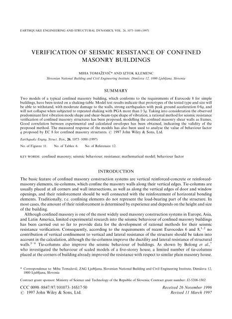
EARTHQUAKE ENGINEERING AND STRUCTURAL DYNAMICS, VOL. 26, 1073—1088 (1997)<br />
VERIFICATION OF SEISMIC RESISTANCE OF CONFINED<br />
MASONRY BUILDINGS<br />
MIHA TOMAZ[ EVIC[ * AND IZTOK KLEMENC<br />
Slovenian National Building and Civil Engineering Institute, Dimic\ eva 12, 1000 Ljubljana, Slovenia<br />
SUMMARY<br />
Two models <strong>of</strong> a typical <strong>confined</strong> <strong>masonry</strong> building, which conforms to the requirements <strong>of</strong> Eurocode 8 for simple<br />
<strong>buildings</strong>, have been tested on a shaking-table. Model test results indicate that prototypes <strong>of</strong> the tested type and size will<br />
be able to withstand, with moderate damage to the walls, strong earthquakes with peak ground acceleration 0·8g, and<br />
will not collapse when subjected to repeated shaking with PGA more than 1·3g. Taking into consideration the observed<br />
predominant first vibration mode shape and shear-beam-type shape <strong>of</strong> vibration, a rational method for <strong>seismic</strong> <strong>resistance</strong><br />
verification <strong>of</strong> <strong>confined</strong> <strong>masonry</strong> structures has been proposed, modelling the <strong>confined</strong> <strong>masonry</strong> shear walls as frames.<br />
Good correlation between experimental and calculated envelopes has been obtained, indicating the validity <strong>of</strong> the<br />
proposed method. The measured response <strong>of</strong> the models has also been used to analyse the value <strong>of</strong> behaviour factor<br />
q proposed by EC 8 for <strong>confined</strong> <strong>masonry</strong> structures. 1997 John Wiley & Sons, Ltd.<br />
Earthquake Engng. Struct. Dyn., 26, 1073—1088 (1997)<br />
No. <strong>of</strong> Figures: 11. No. <strong>of</strong> Tables: 6. No. <strong>of</strong> References: 12.<br />
KEY WORDS: <strong>confined</strong> <strong>masonry</strong>; <strong>seismic</strong> behaviour; <strong>resistance</strong>; mathematical model; behaviour factor<br />
INTRODUCTION<br />
The basic feature <strong>of</strong> <strong>confined</strong> <strong>masonry</strong> construction systems are vertical reinforced-concrete or reinforced<strong>masonry</strong><br />
elements, tie-columns, which confine the <strong>masonry</strong> walls along their vertical edges. Tie-columns are<br />
usually placed at all corners and wall intersections, as well as along the vertical edges <strong>of</strong> door and window<br />
openings, and their reinforcement should be well connected with the reinforcement <strong>of</strong> horizontal bonding<br />
elements. Traditionally, r.c. confining elements do not represent the load-bearing part <strong>of</strong> the structure. In<br />
most cases, the amount <strong>of</strong> their reinforcement is determined by experience and depends on the height and size<br />
<strong>of</strong> the building.<br />
Although <strong>confined</strong> <strong>masonry</strong> is one <strong>of</strong> the most widely used <strong>masonry</strong> construction systems in Europe, Asia,<br />
and Latin America, limited experimental research into the <strong>seismic</strong> behaviour <strong>of</strong> <strong>confined</strong> <strong>masonry</strong> <strong>buildings</strong><br />
has been carried out so far to provide data for the development <strong>of</strong> rational methods for their <strong>seismic</strong><br />
<strong>resistance</strong> verification. Consequently, according to the requirements <strong>of</strong> recent Eurocodes 6 and 8, no<br />
contribution <strong>of</strong> vertical confinement to vertical and lateral <strong>resistance</strong> <strong>of</strong> the structure should be taken into<br />
account in the calculation, although the tie-columns improve the ductility and lateral <strong>resistance</strong> <strong>of</strong> structural<br />
walls. Tie-columns also improve the <strong>seismic</strong> behaviour <strong>of</strong> <strong>buildings</strong>. As shown by Bolong et al.,<br />
who investigated the behaviour <strong>of</strong> scaled models <strong>of</strong> a five-storey house, a limited number <strong>of</strong> tie-columns<br />
placed at the corners <strong>of</strong> building already improved the <strong>resistance</strong> with respect to similar plain <strong>masonry</strong> house.<br />
* Correspondence to: Miha Tomaz\ evic\ , ZAG Ljubljana, Slovenian National Building and Civil Engineering Institute, Dimic\ eva 12,<br />
1000 Ljubljana, Slovenia<br />
Contract grant sponsor: Ministry <strong>of</strong> Science and Technology <strong>of</strong> the Republic <strong>of</strong> Slovenia; Contract grant number: J2-5208-1502<br />
CCC 0098—8847/97/101073—16$17·50 Received 26 November 1996<br />
1997 John Wiley & Sons, Ltd. Revised 11 March 1997
1074 M. TOMAZ[ EVIC[ AND I. KLEMENC<br />
Bolong et al. concluded that increased number <strong>of</strong> vertical tie-columns would further increase the building’s<br />
<strong>seismic</strong> <strong>resistance</strong>.<br />
To obtain additional data regarding the <strong>seismic</strong> behaviour, two models <strong>of</strong> a typical three-storey <strong>confined</strong><br />
<strong>masonry</strong> building have been recently tested on the shaking-table at Slovenian National Building and Civil<br />
Engineering Institute (ZAG) in Ljubljana, Slovenia. The experiments have been aimed at investigating the<br />
mechanism <strong>of</strong> <strong>seismic</strong> behaviour and obtaining data needed for the development <strong>of</strong> a rational method for<br />
<strong>seismic</strong> <strong>resistance</strong> verification.<br />
DESCRIPTION OF EXPERIMENTS<br />
The structural system <strong>of</strong> the prototype consists <strong>of</strong> perimetral walls, pierced with window and/or door<br />
openings on all four sides, and two internal walls, which separate the plan <strong>of</strong> the building into four units.<br />
Whereas the building is symmetrical in the shorter direction, a slight asymmetry in the longer direction is<br />
a result <strong>of</strong> non-symmetric position <strong>of</strong> openings along the walls, as well as non-symmetric position <strong>of</strong> internal<br />
wall in that direction. Floors are monolithic reinforced-concrete, cast in situ slabs, supported by structural<br />
walls in both orthogonal directions. Although the dimensions <strong>of</strong> models, built at 1:5 scale, have been<br />
accommodated to the dimensions <strong>of</strong> the steel platform <strong>of</strong> the shaking-table at ZAG, the dimensions and<br />
structural characteristics <strong>of</strong> the corresponding actual prototype building are still within the limits <strong>of</strong> usual<br />
design practice (wall/floor area ratio being 5·0 per cent in longitudinal and 5·6 per cent in transverse direction<br />
Figure 1. Disposition <strong>of</strong> tie-columns and dimensions <strong>of</strong> models in plan (in cm)<br />
Earthquake Engng. Struct. Dyn., 26, 1073—1088 (1997)<br />
1997 John Wiley & Sons, Ltd.
SEISMIC RESISTANCE OF CONFINED MASONRY BUILDINGS 1075<br />
Figure 2. Disposition <strong>of</strong> tie-columns and dimensions <strong>of</strong> models in elevation. Shear walls A and C (a) and (b) shear wall 1 (in cm)<br />
Table I. Mechanical properties <strong>of</strong> prototype and model materials<br />
Prototype Model Prot./Model<br />
Compressive strength <strong>of</strong> <strong>masonry</strong> 5·0 MPa 1·27 MPa 3·9<br />
Tensile strength <strong>of</strong> <strong>masonry</strong> 0·35 MPa 0·12 MPa 2·9<br />
Modulus <strong>of</strong> elasticity <strong>of</strong> <strong>masonry</strong> 3500 MPa 942 MPa 3·7<br />
Shear modulus <strong>of</strong> <strong>masonry</strong> 500 MPa 185 MPa 2·7<br />
Compressive strength <strong>of</strong> concrete 25·0 MPa 10·8 MPa 2·3<br />
Yield stress <strong>of</strong> reinforcing steel 240·0 MPa not modeled —<br />
<strong>of</strong> the building). The structural layout <strong>of</strong> the modified prototype building in plan conforms to the requirements<br />
<strong>of</strong> EC 8 for ‘simple <strong>buildings</strong>’. For such <strong>buildings</strong>, an explicit verification <strong>of</strong> the <strong>seismic</strong> <strong>resistance</strong> is not<br />
mandatory. The dimensions <strong>of</strong> the models in plan and elevation are shown in Figures 1 and 2, respectively.<br />
In the design <strong>of</strong> the models and model materials, the basic requirements <strong>of</strong> reproducing the dynamic<br />
behaviour and failure mechanism, i.e. the similarity in the distribution <strong>of</strong> masses and stiffnesses along the<br />
height <strong>of</strong> the prototype and the model, as well as similarity in the ratio between the working stresses in the<br />
walls and strength <strong>of</strong> <strong>masonry</strong> materials, have been followed. Consequently, model <strong>masonry</strong> materials that<br />
had the strength reduced close to the geometrical scale, but with the same strain characteristics, specific mass<br />
and damping, as prototype materials, have been prepared. Mechanical properties <strong>of</strong> prototype and model<br />
materials are given in Table I. The resulting modelling factors, however, which should be used when referring<br />
the model test results to prototype, are presented in Table II.<br />
Commercially available fully annealed wire has been used to reinforce the tie-columns. Four bars, 3·2 mm<br />
diameter, have been used at corners and wall intersections, and 2 bars have been used at the vertical borders<br />
<strong>of</strong> door and window openings. In order to model the missing live load, lead bricks (160 kg at each floor level)<br />
1997 John Wiley & Sons, Ltd. Earthquake Engng. Struct. Dyn., 26, 1073—1088 (1997)
1076 M. TOMAZ[ EVIC[ AND I. KLEMENC<br />
Table II. Modeling scale factors<br />
Modeling factor<br />
Physical quantity Relationship True model This study<br />
Length (¸) S 5 5<br />
<br />
"¸/¸<br />
Strength ( f ) S "f /f "S 5 2·92<br />
<br />
Strain (ε) S "ε /ε 1 1<br />
<br />
Sp. mass (γ) S "γ /γ 1 1<br />
<br />
Displacement (d) S "S 5 5<br />
<br />
Force (F) S "SS 125 72·9<br />
<br />
Time (t) S (S S /S ) 2·24 2·93<br />
<br />
Frequency (ω) S "1/S 0·45 0·34<br />
<br />
Velocity (v) S "(S S /S ) 2·24 1·71<br />
<br />
Acceleration (a) S "S /(S S ) 1 0·58<br />
<br />
Figure 3. Modelled earthquake accelerogram (a) and (b) absolute acceleration response spectrum<br />
were fixed to the floors, so that the resulting masses concentrated at first, second, and third floor level <strong>of</strong> the<br />
models amounted to 501, 501, and 377 kg, respectively.<br />
The first 24 s <strong>of</strong> the ground acceleration record <strong>of</strong> Montenegro earthquake <strong>of</strong> 15 April 1979, N—S<br />
component recorded at Petrovac, with peak ground acceleration 0·43g have been used for simulation <strong>of</strong><br />
earthquake ground motion. Original record has been compressed in time by 2·24-times to take into account<br />
the chosen modelling scale and conditions <strong>of</strong> complete model similarity (Figure 3). However, displacement<br />
time history, obtained by integration <strong>of</strong> the modelled ground acceleration record, has been used to drive the<br />
shaking table.<br />
Both models have been tested by subjecting them to the same sequence <strong>of</strong> <strong>seismic</strong> excitation, with<br />
gradually increased intensity <strong>of</strong> motion in each successive test run up until the final collapse <strong>of</strong> the models.<br />
Whereas model M1 has been tested longitudinally, model M2 was subjected to excitation along its transverse<br />
axis. In this way, possible torsional effects in the case <strong>of</strong> non-symmetric <strong>confined</strong> <strong>masonry</strong> structures could<br />
have been studied. The basic parameters <strong>of</strong> the shaking-table motion in each successive test run, such as<br />
maximum displacement and acceleration, as well as Arias intensity and input energy per unit <strong>of</strong> mass, are<br />
given in Table III. Test runs are designated according to programmed input intensity <strong>of</strong> the shaking-table<br />
motion: R100 (100 per cent) corresponds to the modelled ground acceleration record. Typical instrumentation<br />
<strong>of</strong> the models is shown in Figure 4.<br />
Earthquake Engng. Struct. Dyn., 26, 1073—1088 (1997)<br />
1997 John Wiley & Sons, Ltd.
SEISMIC RESISTANCE OF CONFINED MASONRY BUILDINGS 1077<br />
Table III. Characteristic parameters <strong>of</strong> shaking-table motion recorded during<br />
shaking-table tests<br />
Maximum Maximum Input Arias<br />
Test displacement acceleration energy intensity<br />
Model run (mm) (m/s) (m/s) (m/s)<br />
R5 0·87 1·12 0·002 0·26<br />
R25 3·38 4·05 0·066 6·65<br />
R50 6·35 9·27 0·236 25·02<br />
M1 R75* 9·21 9·65 0·471 47·05<br />
R100 12·45 14·23 0·777 78·46<br />
R150 18·53 17·08 1·879 190·34<br />
R200 24·29 28·31 2·536 238·64<br />
R5 1·00 1·02 0·002 0·19<br />
R25 3·17 3·93 0·071 7·43<br />
R50* 6·63 7·02 0·236 23·54<br />
M2 R75 10·01 11·75 0·507 55·11<br />
R100 12·74 13·85 0·961 113·81<br />
R150 18·92 17·56 1·688 179·28<br />
R200 24·27 23·42 2·385 234·01<br />
R200/1 23·72 20·84 2·436 237·62<br />
Note: *Elastic limit, maximum <strong>resistance</strong>, ultimate state<br />
Figure 4. Instrumentation <strong>of</strong> model M1<br />
1997 John Wiley & Sons, Ltd. Earthquake Engng. Struct. Dyn., 26, 1073—1088 (1997)
1078 M. TOMAZ[ EVIC[ AND I. KLEMENC<br />
EXPERIMENTAL RESULTS<br />
Damage propagation and failure mechanism<br />
The behaviour <strong>of</strong> both models was similar, although different position <strong>of</strong> models M1 and M2 on the<br />
platform and resulting different <strong>resistance</strong>, stiffness, and non-symmetry, caused slightly different damage<br />
propagation in the two cases. Diagonally oriented cracks in the middle part <strong>of</strong> perimetral walls in the<br />
direction <strong>of</strong> motion, have developed in the initial phases <strong>of</strong> testing. During the test runs to follow, the existing<br />
cracks propagated and new diagonal cracks formed, oriented in the other diagonal direction. Horizontal<br />
cracks, passing through mortar joints, have been observed in the parapets.<br />
Model M1 has been seriously damaged during test run R150 (see Table III for the parameters <strong>of</strong> shaking<br />
table motion). In all storeys and in all walls standing in the direction <strong>of</strong> <strong>seismic</strong> excitation, a system <strong>of</strong> cracks<br />
developed, oriented in both diagonal directions. All parapets have been also damaged: in some <strong>of</strong> them,<br />
horizontal, in most <strong>of</strong> them, however, diagonally oriented cracks formed. Although most <strong>of</strong> the cracks passed<br />
through mortar joints, the initiation <strong>of</strong> crushing <strong>of</strong> <strong>masonry</strong> units has been also observed in the middle, most<br />
stressed parts <strong>of</strong> the walls, located in the first storey. After test run R150, cracks in the central wall in the<br />
direction <strong>of</strong> <strong>seismic</strong> motion have been also observed. Whereas horizontal cracks prevailed in that wall in the<br />
first, diagonal cracks occurred in the second storey. Although severe stiffness degradation <strong>of</strong> model M1 has<br />
been observed as a result <strong>of</strong> heavy damage to the walls, and, consequently, large displacement amplitudes <strong>of</strong><br />
vibration have been measured, no damage has been observed to the walls, orthogonal to <strong>seismic</strong> excitation.<br />
Also, no damage has been observed to confining elements—tie-column and floor slabs.<br />
Heavy structural damage occurred during test run R200. In the middle sections <strong>of</strong> the walls, located in the<br />
first floor, <strong>masonry</strong> units crushed, the walls separated from the confining elements, and disintegrated. Parts <strong>of</strong><br />
the central wall failed in shear, in some parts, however, sliding shear failure was the reason <strong>of</strong> collapse. During<br />
test run R200 the amplitudes <strong>of</strong> vibration immensely increased, so that the walls orthogonal to <strong>seismic</strong><br />
excitation broke. Horizontal cracks at the connection <strong>of</strong> the walls to the foundation and first floor slab, as<br />
well as diagonal cracks in the corner parts <strong>of</strong> these walls developed. Severe damage to vertical tie-columns<br />
has been also observed. Crushing <strong>of</strong> concrete took place at the joints between vertical tie-columns and horizontal<br />
bond-beams. In some cases, rupture <strong>of</strong> vertical reinforcing steel in tie-columns has been also observed.<br />
Model M2 was seriously damaged during test run R100. A system <strong>of</strong> cracks, oriented in both diagonal<br />
directions, developed in all walls in the direction <strong>of</strong> <strong>seismic</strong> motion. Although most <strong>of</strong> the cracks passed<br />
through mortar joints, crushing <strong>of</strong> <strong>masonry</strong> units has been observed in the most stressed parts <strong>of</strong> wall<br />
elements. Cracks in the joints between <strong>masonry</strong> units have been observed in the parapets. However, no<br />
damage has been observed to shear-walls, orthogonal to the direction <strong>of</strong> <strong>seismic</strong> excitation.<br />
During test run R150, crushed <strong>masonry</strong> units started falling <strong>of</strong>f the walls <strong>of</strong> the first and second storey.<br />
Significant damage to elements <strong>of</strong> the central shear-wall, and damage to transverse parts <strong>of</strong> the corner walls<br />
occurred. The beginning <strong>of</strong> crushing <strong>of</strong> micro-concrete at the joints between vertical and horizontal tying<br />
elements has been also observed. The extent <strong>of</strong> damage to model M2 during test run R200 significantly<br />
changed the dynamic characteristics <strong>of</strong> the model. As was the case <strong>of</strong> model M1, practically all walls in the<br />
first storey (ground floor) disintegrated, so that only vertical confining elements supported the upper two<br />
storeys. Heavy damage occurred to r.c. tie-columns, whereas no damage to floor slabs has been observed. At<br />
the connection <strong>of</strong> vertical tie-columns to bond-beams or slabs, crushing <strong>of</strong> concrete and buckling <strong>of</strong><br />
reinforcing steel took place. Because <strong>of</strong> large lateral displacements, damage to transverse walls in the first<br />
storey increased significantly.<br />
To correlate the results <strong>of</strong> experiments with calculations and verify the proposed numerical model, three<br />
limit states have been defined in the behaviour <strong>of</strong> the models:<br />
(a) Elastic limit, defined by the occurrence <strong>of</strong> the first major damage to the model’s structural elements<br />
that caused noticeable decay <strong>of</strong> the first natural frequency <strong>of</strong> vibration,<br />
Earthquake Engng. Struct. Dyn., 26, 1073—1088 (1997)<br />
1997 John Wiley & Sons, Ltd.
SEISMIC RESISTANCE OF CONFINED MASONRY BUILDINGS 1079<br />
Figure 5. Mechanism <strong>of</strong> collapse <strong>of</strong> model M2<br />
(b) Maximum <strong>resistance</strong>, defined by the maximum base shear resisted, and<br />
(c) Ultimate state, representing the characteristics <strong>of</strong> the models just before collapse (i.e., at the moment<br />
when the instruments have been removed from the models).<br />
Typical damage to models at ultimate state is shown in Figure 5. The testing phases where the so-defined<br />
limit states have been observed, however, are indicated in Table III.<br />
DYNAMIC RESPONSE<br />
Typical recorded acceleration and displacement response time-histories at elastic limit (test run R50) and at<br />
ultimate state (test run R200) are shown in Figure 6. Since the analysis <strong>of</strong> the floor response indicated that the<br />
first vibration mode was predominant, the first vibration mode shape has been evaluated by taking into<br />
account the average values <strong>of</strong> three maximum displacement amplitudes at oscillations in positive and<br />
negative direction. The first vibration mode shapes at characteristic limit states are presented in Figure 7.<br />
Both models responded similarly, representing a shear-beam-type vibration system. In the last phases <strong>of</strong><br />
testing, however, where the s<strong>of</strong>tening <strong>of</strong> the first storey due to disintegration <strong>of</strong> <strong>masonry</strong> walls changed the<br />
distribution <strong>of</strong> stiffnesses along the height, the models no longer vibrated as a shear beam.<br />
The decay <strong>of</strong> the first natural frequency <strong>of</strong> vibration and changes in coefficient <strong>of</strong> equivalent viscous<br />
damping have been determined by analysing free vibration <strong>of</strong> the model, caused by hitting the model with<br />
impact hammer after each testing phase, as well as by analysing the <strong>seismic</strong> response. Half-power bandwidth<br />
method has been used to estimate the values <strong>of</strong> coefficient <strong>of</strong> equivalent viscous damping. The values <strong>of</strong> the<br />
first frequency <strong>of</strong> vibration and coefficient <strong>of</strong> equivalent viscous damping at characteristic limit states are<br />
given in Table IV.<br />
As can be seen, frequency decay is in good correlation with the observed damage to structural walls.<br />
Significant differences between the values <strong>of</strong> natural frequencies obtained from free vibration records at small<br />
amplitudes <strong>of</strong> vibration at the end <strong>of</strong> each testing phase (impact hammer test), and those obtained by Fourier<br />
analysis <strong>of</strong> the models’ response during the strong shaking, can be noticed. As regards the values <strong>of</strong> coefficient<br />
<strong>of</strong> equivalent viscous damping, the values obtained on the basis <strong>of</strong> logarithmic decrement <strong>of</strong> damping and<br />
1997 John Wiley & Sons, Ltd. Earthquake Engng. Struct. Dyn., 26, 1073—1088 (1997)
1080 M. TOMAZ[ EVIC[ AND I. KLEMENC<br />
Figure 6. Typical measured displacement response time-histories in linear (a) and (b) in non-linear range <strong>of</strong> vibration<br />
measured hysteretic behaviour seem more realistic than the values obtained by half-power bandwidth<br />
method.<br />
Taking into consideration the predominant first vibration mode shape and shear-beam-type shape <strong>of</strong><br />
vibration, and assuming that the observed first mode shape is stable during the shaking, and neglecting the<br />
damping, base shear and storey shear can be determined at each instant <strong>of</strong> time as a sum <strong>of</strong> inertia forces<br />
acting at floor levels:<br />
BS" <br />
<br />
m a " <br />
Q (1)<br />
<br />
<br />
where BS is the base shear, Q <br />
the ith storey shear, m <br />
the mass concentrated at ith storey level, a <br />
the<br />
acceleration <strong>of</strong> the ith mass and n the number <strong>of</strong> storeys.<br />
Earthquake Engng. Struct. Dyn., 26, 1073—1088 (1997)<br />
1997 John Wiley & Sons, Ltd.
SEISMIC RESISTANCE OF CONFINED MASONRY BUILDINGS 1081<br />
Figure 7. First natural vibration mode shapes<br />
Table IV. First natural frequency and coefficient <strong>of</strong> equivalent viscous damping<br />
Model M1<br />
Model M2<br />
Test run (1) (2) (3) (1) (2) (3)<br />
Virgin model 22·0 21·9 — 21·4 21·9 —<br />
R50 21·4 20·3 15·6 15·9 15·8 15·2<br />
f (Hz) R75 17·4 17·2 14·3 13·5 12·9 10·9<br />
R100 15·6 14·1 11·9 8·5 8·2 8·8<br />
R150 7·1 6·3 7·0 4·5 4·1 3·3<br />
Virgin model 4·8 6·7 — 3·7 4·0 —<br />
R50 5·3 9·9 9·9 5·9 9·0 6·1<br />
ξ (%) R75 7·2 13·7 10·8 8·0 11·2 5·5<br />
R100 9·8 21·8 7·7 10·1 14·3 5·4<br />
R150 19·1 25·2 9·5 15·1 17·4 15·3<br />
Frequency: (1) impact hammer response—after the test<br />
(2) Fourier spectrum <strong>of</strong> impact hammer response—after the test<br />
(3) Fourier spectrum <strong>of</strong> <strong>seismic</strong> response—during the test<br />
Damping: (1) logarithmic decrement, impact hammer response—after the test<br />
(2) half-power band-width, impact hammer response—after the test<br />
(3) hysteretic damping, <strong>seismic</strong> response—during the test<br />
1997 John Wiley & Sons, Ltd. Earthquake Engng. Struct. Dyn., 26, 1073—1088 (1997)
1082 M. TOMAZ[ EVIC[ AND I. KLEMENC<br />
Figure 8. Base shear—first storey drift hysteresis envelopes<br />
Table V. Stiffness degradation at characteristic limit states<br />
K <br />
K <br />
K <br />
Model Storey (kN/mm) (kN/mm) K <br />
/K <br />
(kN/mm) K <br />
/K <br />
3 24·09 35·46 1·47 1·87 0·08<br />
M1 2 28·62 38·75 1·35 0·49 0·02<br />
1 51·04 54·11 1·06 0·63 0·01<br />
3 15·96 9·52 0·60 8·74 0·55<br />
M2 2 19·19 9·24 0·45 2·19 0·11<br />
1 27·28 11·81 0·43 0·41 0·02<br />
The relationship between the base shear and relative storey displacement for both models is shown in<br />
Figure 8. As can be seen, because <strong>of</strong> different distribution <strong>of</strong> structural walls in longitudinal (M1) and<br />
transverse direction (M2), different strengths and rigidities have been measured. Mainly because <strong>of</strong> longitudinal<br />
central wall, not pierced with window and door openings, the rigidity <strong>of</strong> the model tested in longitudinal<br />
direction was greater than that <strong>of</strong> the model tested transversely. As regards the lateral <strong>resistance</strong> attained in<br />
longitudinal direction, the differences were not so significant. Obviously, the ultimate mechanism and<br />
contribution <strong>of</strong> vertical r.c. confining elements to the <strong>resistance</strong> <strong>of</strong> model <strong>buildings</strong> reduced the differences<br />
observed in the rigidity during the monolithic phase <strong>of</strong> behaviour.<br />
On the basis <strong>of</strong> storey shear—relative storey drift hysteresis loops, the values <strong>of</strong> storey stiffness and<br />
hysteretic damping have been evaluated for each oscillation cycle. In the analysis, storey stiffness was defined<br />
as the average value <strong>of</strong> secant stiffness between two amplitude peaks (peak-to-peak stiffness). As can be seen<br />
in Table V, stiffness degradation is in good correlation with the observed damage to models and the<br />
measured first natural frequency decay.<br />
Mechanism <strong>of</strong> action <strong>of</strong> tie-columns<br />
As the analysis <strong>of</strong> the measured lateral load—strain <strong>of</strong> reinforcement relationships indicated, monolithic<br />
behaviour <strong>of</strong> the <strong>confined</strong> wall’s section and alteration <strong>of</strong> strain in the tie-columns’ reinforcing bars from<br />
Earthquake Engng. Struct. Dyn., 26, 1073—1088 (1997)<br />
1997 John Wiley & Sons, Ltd.
SEISMIC RESISTANCE OF CONFINED MASONRY BUILDINGS 1083<br />
Table VI. Seismic <strong>resistance</strong> <strong>of</strong> prototype <strong>buildings</strong><br />
Max. ground<br />
Dynamic<br />
acceleration Base shear amplification<br />
Direction Limit state (g) coefficient factor<br />
Elastic limit (R75) 0·57 1·14 2·05<br />
Longitudinal Maximum <strong>resistance</strong> (R100) 0·84 1·73 2·99<br />
Ultimate state (R200) 1·67 0·61 0·43<br />
Elastic limit (R50) 0·42 0·61 2·40<br />
Transverse Maximum <strong>resistance</strong> (R100) 0·82 1·25 1·83<br />
Ultimate state (R200/1) 1·38 0·64 0·66<br />
compression to tension has been observed at the beginning <strong>of</strong> test, at small amplitudes <strong>of</strong> vibration. After<br />
severe cracks in the <strong>masonry</strong> wall panel developed at large amplitudes <strong>of</strong> vibration, tension in reinforcing<br />
bars prevailed at both directions <strong>of</strong> vibration. This indicates that interaction forces between the <strong>masonry</strong> wall<br />
panel and r.c. tie-columns developed, inducing additional compressive stresses in the <strong>masonry</strong> panel. Once<br />
cracked, the <strong>masonry</strong> panel pushed the tie-columns sidewards and induced tension in the reinforcing bars in<br />
both directions <strong>of</strong> vibration <strong>of</strong> the model structure. The measured relationships are in good correlation with<br />
the results <strong>of</strong> tests <strong>of</strong> single <strong>confined</strong> <strong>masonry</strong> wall panels subjected to constant vertical and cyclic lateral<br />
loading. On the basis <strong>of</strong> damage observation and measurements <strong>of</strong> strain induced in the tie-columns it can<br />
be concluded that the shear walls can be modelled as frames, consisting <strong>of</strong> piers represented by <strong>confined</strong><br />
<strong>masonry</strong> walls, and spandrels represented by parapets, bond-beams and effective part <strong>of</strong> floor slabs in the<br />
direction <strong>of</strong> <strong>seismic</strong> action. Spandrels behave as coupling beams, which connect the walls and transfer<br />
bending moments.<br />
Seismic <strong>resistance</strong> <strong>of</strong> prototype <strong>buildings</strong><br />
Modelling scale factors, given in Table II, should be used for referring the model test results to prototype<br />
<strong>buildings</strong>. Since the values <strong>of</strong> the base shear and story shear have been determined on the basis <strong>of</strong> the<br />
measured accelerations, the calculated values should be multiplied by acceleration scale factor S <br />
"0·58<br />
when referred to as prototype values. The values <strong>of</strong> maximum ground acceleration, base shear coefficient<br />
(base shear to weight <strong>of</strong> the building ratio) and dynamic amplification factor (maximum response to<br />
shaking-table acceleration ratio) at elastic limit, maximum <strong>resistance</strong> and at ultimate state, are given in<br />
Table VI.<br />
As can be seen, the maximum <strong>resistance</strong> <strong>of</strong> prototype <strong>buildings</strong> is relatively high. Longitudinally and<br />
transversely, the three-storey <strong>confined</strong> <strong>masonry</strong> building will be able to withstand, with limited damage to<br />
the walls, a strong earthquake with peak ground acceleration (PGA) corresponding to 0·8g. Energy<br />
dissipation capacity <strong>of</strong> the structure will prevent the building from collapse even in the case when subjected to<br />
subsequent stronger shaking with PGA exceeding 1·3g. However, at this level <strong>of</strong> earthquake ground motion,<br />
the damage caused to <strong>masonry</strong> wall panels will be beyond repair.<br />
The analysis <strong>of</strong> <strong>seismic</strong> <strong>resistance</strong> <strong>of</strong> the tested building type indicates that, even if classified as ‘simple<br />
building’ according to EC 8, and without any verification <strong>of</strong> <strong>seismic</strong> <strong>resistance</strong>, the structural configuration<br />
will ensure the <strong>buildings</strong> the required degree <strong>of</strong> <strong>seismic</strong> <strong>resistance</strong>. It should be borne in mind that the<br />
required wall/floor area for simple <strong>confined</strong> <strong>masonry</strong> <strong>buildings</strong> is 5 per cent (actual values are 5·0 per cent in<br />
longitudinal and 5·6 per cent in transverse direction <strong>of</strong> the building).<br />
1997 John Wiley & Sons, Ltd. Earthquake Engng. Struct. Dyn., 26, 1073—1088 (1997)
1084 M. TOMAZ[ EVIC[ AND I. KLEMENC<br />
SEISMIC RESISTANCE VERIFICATION<br />
Storey <strong>resistance</strong> envelope<br />
In case that the relationship between the <strong>resistance</strong> <strong>of</strong> the critical storey and corresponding storey drift can<br />
be assessed, the <strong>seismic</strong> <strong>resistance</strong> <strong>of</strong> the building can be verified by simple comparing the storey <strong>resistance</strong><br />
envelope with the design <strong>seismic</strong> action and global ductility requirements. The idea to analyse the <strong>resistance</strong><br />
<strong>of</strong> a structure by step-wise increasing the lateral loads, acting on the structure, and modifying the system<br />
when plastic hinges develop, is not new (push-over method). However, once the maximum <strong>resistance</strong> is<br />
attained and the structure is changed into a mechanism, it is no longer possible to follow the deformations by<br />
calculation. Therefore, instead <strong>of</strong> lateral loads, lateral displacements are imposed to the structure. In this way,<br />
<strong>resistance</strong> <strong>of</strong> structural elements to imposed displacements can be followed all the way up to the structure’s<br />
collapse.<br />
When this idea has been first applied to <strong>masonry</strong> <strong>buildings</strong>, a simple pier mechanism action <strong>of</strong> walls has<br />
been assumed. Today, the shear walls, pierced by window and door openings, are modelled as frames, so that<br />
additional axial forces, developed in the piers due to overturning moments, are automatically taken into<br />
account. Because <strong>of</strong> structural configuration <strong>of</strong> <strong>confined</strong> <strong>masonry</strong> structures, however, these forces have little<br />
effect on the <strong>resistance</strong>. On the basis <strong>of</strong> relevant mechanism, the storey <strong>resistance</strong> envelope is evaluated as<br />
a superposition <strong>of</strong> <strong>resistance</strong> envelopes <strong>of</strong> all structural walls in the storey considered. The assumption <strong>of</strong><br />
rigid horizontal floor diaphragm action makes possible the distribution <strong>of</strong> <strong>seismic</strong> actions among the piers<br />
according to their stiffnesses. In case that the shear wall consists <strong>of</strong> flanged sections <strong>of</strong> piers (corner walls,<br />
T, # shape sections), the contribution <strong>of</strong> the flange should be taken into account. However, in the case <strong>of</strong><br />
the verification for shear, the web, i.e. part <strong>of</strong> the wall parallel to <strong>seismic</strong> action, represents the resisting<br />
element. Because <strong>of</strong> low G/E ratio <strong>of</strong> <strong>masonry</strong> and, hence, predominant shear deformations in the case <strong>of</strong><br />
squat walls, the assumption that the walls are separated along vertical joints is sometimes acceptable even in<br />
the case <strong>of</strong> flanged walls, where good connection between the adjoining walls is provided.<br />
Assuming triangular distribution <strong>of</strong> displacements along the height <strong>of</strong> the building, the structure<br />
is displaced by a small value. The shear walls are deformed according to the assumed structural model<br />
and the resisting forces in structural members are calculated. Since the mass centres <strong>of</strong> individual storeys<br />
are displaced, torsional rotation might take place. In such a case, the displacements <strong>of</strong> individual piers<br />
are accordingly modified. The calculation is repeated step-by-step by increasing the imposed displacements.<br />
Once the walls enter into the non-linear range, the structural system <strong>of</strong> the building and stiffness<br />
matrices are modified. Stiffness and <strong>resistance</strong> <strong>of</strong> individual walls in each step <strong>of</strong> calculation are determined<br />
considering the calculated storey displacement and idealized <strong>resistance</strong> envelopes <strong>of</strong> structural walls in each<br />
storey.<br />
As a result <strong>of</strong> calculation, relationship between the <strong>resistance</strong> <strong>of</strong> the critical storey and interstorey drift, i.e.<br />
the <strong>resistance</strong> envelope is obtained. At the given lateral displacement <strong>of</strong> the ith wall d <br />
, the resisting storey<br />
shear H <br />
is determined as a sum <strong>of</strong> <strong>resistance</strong>s <strong>of</strong> structural walls H <br />
in the storey considered:<br />
H " <br />
H (2)<br />
<br />
<br />
where the <strong>resistance</strong> <strong>of</strong> the ith wall H depends on the deformation <strong>of</strong> the wall d . In case that the <strong>resistance</strong><br />
<br />
envelope <strong>of</strong> structural walls is idealized with trilinear relationship, the following simple conditions<br />
determine the contributing stiffness and <strong>resistance</strong> <strong>of</strong> individual structural walls (Figure 9):<br />
H <br />
"d <br />
K <br />
; K <br />
"K <br />
if d <br />
)d <br />
, (3a)<br />
H <br />
"H <br />
#β <br />
(d <br />
!d <br />
); K <br />
" H <br />
d <br />
if d <br />
(d <br />
)d <br />
, (3b)<br />
Earthquake Engng. Struct. Dyn., 26, 1073—1088 (1997)<br />
1997 John Wiley & Sons, Ltd.
SEISMIC RESISTANCE OF CONFINED MASONRY BUILDINGS 1085<br />
H <br />
"H <br />
!β <br />
(d <br />
!d <br />
); K <br />
" H <br />
d <br />
if d <br />
(d <br />
)d <br />
(3b)<br />
H <br />
"0; K <br />
"0 if d <br />
'd <br />
, (3c)<br />
where d <br />
, d <br />
, d <br />
are the displacement <strong>of</strong> the ith wall at elastic limit, maximum <strong>resistance</strong> and ultimate<br />
state, respectively, H <br />
, H <br />
the crack limit and <strong>resistance</strong> capacity <strong>of</strong> the ith wall, respectively, β <br />
, β <br />
the<br />
stiffness degradation parameters, K <br />
, K <br />
the stiffness and effective stiffness if the ith wall, respectively, and<br />
n the number <strong>of</strong> walls.<br />
By using relevant equations for shear and flexural <strong>resistance</strong> and stiffness <strong>of</strong> <strong>confined</strong> <strong>masonry</strong> walls,<br />
developed within a previous study, the <strong>resistance</strong> envelopes corresponding to models M1 and M2 have<br />
been calculated. The calculated envelopes are correlated with the experimentally obtained curves in<br />
Figure 10. As can be seen, good correlation between experimental and calculated envelopes has been<br />
Figure 9. Idealization <strong>of</strong> experimentally obtained <strong>resistance</strong> envelope <strong>of</strong> a <strong>confined</strong> <strong>masonry</strong> wall<br />
Figure 10. Comparison between experimental and calculated storey <strong>resistance</strong> envelopes. (a) Model M1 and (b) model M2<br />
1997 John Wiley & Sons, Ltd. Earthquake Engng. Struct. Dyn., 26, 1073—1088 (1997)
1086 M. TOMAZ[ EVIC[ AND I. KLEMENC<br />
obtained in both cases, which indicates the practical validity <strong>of</strong> the proposed model for <strong>seismic</strong> <strong>resistance</strong><br />
verification <strong>of</strong> <strong>confined</strong> <strong>masonry</strong> structures.<br />
If, in the case <strong>of</strong> <strong>seismic</strong> <strong>resistance</strong> verification, the ultimate <strong>resistance</strong> and ductility <strong>of</strong> the structure<br />
conform with code requirements (base shear, required ductility factor), the <strong>seismic</strong> <strong>resistance</strong> <strong>of</strong> the building is<br />
adequate.<br />
Behaviour factor<br />
As a result <strong>of</strong> ductility and energy dissipation capacity, there is usually no need that the structure be<br />
designed for strength, i.e. for the expected elastic <strong>seismic</strong> load H <br />
. The structure is designed for the ultimate<br />
load H <br />
. The factor <strong>of</strong> reduction <strong>of</strong> elastic loads, expressed in a simplified way as a ratio between the two, is<br />
called behaviour factor, or force reduction factor q"H <br />
/H <br />
.<br />
Taking advantage <strong>of</strong> the obtained experimental data, an attempt has been made to assess the value <strong>of</strong><br />
structural behaviour factor for the case <strong>of</strong> the tested models. The actual <strong>resistance</strong> H <br />
<strong>of</strong> the tested prototype<br />
<strong>buildings</strong>, complying with the requirements <strong>of</strong> EC 8 for simple <strong>buildings</strong>, where <strong>seismic</strong> <strong>resistance</strong> verification<br />
is not mandatory, by far exceeded the expected design value even in severe <strong>seismic</strong> situation. Therefore, in the<br />
particular case studied, q factor has been evaluated by assuming that maximum intensity <strong>of</strong> simulated<br />
earthquake ground motion represented the design level <strong>of</strong> <strong>seismic</strong> loading. To estimate the behaviour factor<br />
according to most simple definition, the experimentally obtained base shear—relative storey displacement<br />
curve has been compared with the response <strong>of</strong> a hypothetical structure with ideal elastic characteristics to<br />
maximum shaking-table motion, which the models had resisted. As a result <strong>of</strong> this comparison, the values <strong>of</strong><br />
behaviour factors q"H <br />
/H <br />
"2·91 and q"2·47 have been obtained for models M1 and M2, respectively,<br />
(Figure 11).<br />
The conclusion can be therefore made that <strong>confined</strong> <strong>masonry</strong> structures possess more energy dissipation<br />
capacity than attributed to by the proposed values <strong>of</strong> behaviour factor q. However, taking into consideration<br />
the fact that limitation <strong>of</strong> story drift is necessary to avoid excessive damage to structural walls (see Figure 5),<br />
the value <strong>of</strong> q factor proposed by EC 8 seems reasonable. Similar conclusions have been obtained by an<br />
analytical study that investigated q factors for <strong>confined</strong> <strong>masonry</strong> <strong>buildings</strong> subjected to Chilean earthquakes.<br />
Figure 11. Evaluation <strong>of</strong> behavior factor q for the case <strong>of</strong> model M1<br />
Earthquake Engng. Struct. Dyn., 26, 1073—1088 (1997)<br />
1997 John Wiley & Sons, Ltd.
SEISMIC RESISTANCE OF CONFINED MASONRY BUILDINGS 1087<br />
Within a previous experimental study, the values <strong>of</strong> behaviour factors q"2·84 and q"3·74 have been<br />
obtained for unreinforced and reinforced <strong>masonry</strong> <strong>buildings</strong> <strong>of</strong> similar configuration and size, respectively.<br />
Correlating the values obtained for all three types <strong>of</strong> <strong>masonry</strong> construction, it can be seen that EC 8 values <strong>of</strong><br />
q factors, proposed for unreinforced (q"1·5), <strong>confined</strong> (q"2·0) and reinforced <strong>masonry</strong> <strong>buildings</strong> (q"2·5),<br />
adequately reflect the assumed differences in the behaviour <strong>of</strong> different types <strong>of</strong> <strong>masonry</strong> structures, but<br />
slightly underestimate their energy dissipation capacity. However, further experimental and analytical<br />
research is needed to confirm these observations.<br />
CONCLUSIONS<br />
Seismic behaviour <strong>of</strong> <strong>confined</strong> <strong>masonry</strong> <strong>buildings</strong> has been experimentally investigated. Two 1:5 scale<br />
models <strong>of</strong> a typical three-storey structure, which conforms to the requirements <strong>of</strong> EC 8 for simple <strong>buildings</strong> in<br />
plan, have been tested on a shaking-table by subjecting them to a series <strong>of</strong> simulated <strong>seismic</strong> ground motions<br />
with increased intensity <strong>of</strong> shaking in each successive test run. The structural system consisted <strong>of</strong> perimetral<br />
shear walls, pierced with window and door openings, and two internal walls, which separated the plan <strong>of</strong> the<br />
building into four units. Tie-columns have been placed at all corners and wall intersections, as well as along<br />
the vertical edges <strong>of</strong> window and door openings. Wall/floor area exceeded 5 per cent in both orthogonal<br />
directions.<br />
Predominant shear-type mechanism defined the <strong>seismic</strong> behaviour <strong>of</strong> the models. In all stories, diagonal<br />
cracks formed in the walls at the attainment <strong>of</strong> maximum <strong>resistance</strong>, whereas crushing <strong>of</strong> concrete and<br />
rupture <strong>of</strong> reinforcement <strong>of</strong> tie-columns with falling out <strong>of</strong> <strong>masonry</strong> in the first storey defined the ultimate<br />
state. With the increased damage to structure, the first natural frequency <strong>of</strong> vibration decayed, but energy<br />
dissipation increased.<br />
The model test results indicate that prototype <strong>buildings</strong> <strong>of</strong> the tested type and size will be able to<br />
withstand, with moderate damage to the walls, strong earthquakes with peak ground acceleration <strong>of</strong> 0·8g,<br />
and will not collapse when subjected to repeated shaking with PGA <strong>of</strong> more than 1·3g. On the basis <strong>of</strong> the<br />
observed behaviour it can be concluded that the requirements <strong>of</strong> EC 8 for simple <strong>confined</strong> <strong>masonry</strong> <strong>buildings</strong><br />
are to severe. Although the tested models represented prototypes <strong>of</strong> good-quality <strong>masonry</strong>, the actual<br />
<strong>resistance</strong> by far exceeded the expected <strong>seismic</strong> loads (design ground acceleration a "0·3g in the zones <strong>of</strong><br />
<br />
high expected <strong>seismic</strong>ity).<br />
The measured response <strong>of</strong> the models has been used to obtain data regarding the values <strong>of</strong> behaviour<br />
factor q proposed by EC 8 for <strong>confined</strong> <strong>masonry</strong> structures. Although the <strong>buildings</strong>, simple by definition <strong>of</strong><br />
EC 8, have not been designed by calculation, the obtained values <strong>of</strong> behaviour factor q indicate that the<br />
requirements <strong>of</strong> EC 8 regarding the design <strong>seismic</strong> actions, might be relaxed. However, further experimental<br />
and analytical studies are needed to confirms these observations.<br />
Model test results have been also used to propose a rational method for <strong>seismic</strong> <strong>resistance</strong> verification <strong>of</strong><br />
<strong>confined</strong> <strong>masonry</strong> structures. Taking into consideration the predominant first vibration mode shape and<br />
shear-beam type shape <strong>of</strong> vibration, the storey <strong>resistance</strong> envelope is calculated by modelling the shear walls<br />
as frames. By imposing triangularly distributed <strong>of</strong> displacements along the height <strong>of</strong> the building, the<br />
structure is displaced step by step and the <strong>resistance</strong> <strong>of</strong> shear walls to imposed displacements is calculated.<br />
Good correlation between experimental and calculated envelopes has been obtained in the particular case<br />
studied, indicating the usability <strong>of</strong> the proposed method.<br />
ACKNOWLEDGMENTS<br />
The research discussed in this contribution has been financed by the Ministry <strong>of</strong> Science and Technology <strong>of</strong><br />
the Republic <strong>of</strong> Slovenia (project J2-5208-1502). As regards the experimental part <strong>of</strong> the project, the<br />
contribution <strong>of</strong> the author’s colleague Mr. Ljubo Petković is gratefully acknowledged.<br />
1997 John Wiley & Sons, Ltd. Earthquake Engng. Struct. Dyn., 26, 1073—1088 (1997)
1088 M. TOMAZ[ EVIC[ AND I. KLEMENC<br />
REFERENCES<br />
1. Eurocode 8, Design Provisions for Earthquake Resistance <strong>of</strong> Structures. Part 1-3: General Rules—Specific Rules for »arious Materials<br />
and Elements, ENV 1998-1-3: 1995, 1995.<br />
2. Eurocode 6, Design <strong>of</strong> Masonry Structures. Part 1-1: General Rules for Buildings. Rules for Reinforced and ºnreinforced Masonry,<br />
ENV 1996-1-1: 1995, 1995.<br />
3. V. Aguila, F. Delfin and M. Astroza, ‘Estudio experimental de soluciones de reparacion y refuerzo para elementos de albanileria’.<br />
Pub. SES I 1/88 (221), Universidad de Chile, Santiago, 1988.<br />
4. Y. Wenzhong and J. Zhaohong, ‘Functions <strong>of</strong> ties concrete columns in brick walls’ Proc. 9th ¼orld Conf. Earthquake Engng.,<br />
Tokyo-Kyoto 6, 139—144 (1988).<br />
5. G. Aguilar, R. Meli, R. Diaz and R. Vasquez-del-Mercado, ‘Influence <strong>of</strong> horizontal reinforcement on the behavior <strong>of</strong> <strong>confined</strong><br />
<strong>masonry</strong> walls’, Proc. 11th ¼orld Conf. Earthquake Engng., Acapulco, paper no.1380 (1996).<br />
6. M. Iiba, H. Mizuno, T. Goto and H. Kato, ‘Shaking table test on <strong>seismic</strong> performance <strong>of</strong> <strong>confined</strong> <strong>masonry</strong> wall’, Proc. 11th ¼orld<br />
Conf. Earthquake Engng., Acapulco, paper no. 659, 1996.<br />
7. Z. Bolong, W. Mingshun and Z. Deyuan, ‘Shaking table study <strong>of</strong> a five-story unreinforced block <strong>masonry</strong> model building<br />
strengthened with reinforced concrete columns and tie bars’, Proc., ºS-PRC Joint ¼orkshop on Seismic Resistance <strong>of</strong> Masonry<br />
Struct., Harbin, IV-11; 1-11, 1988.<br />
8. Bulletin <strong>of</strong> the Strong-Motion Earthquake Accelerograms. No. 1, IZIIS, Skopje, 1984.<br />
9. A. Arias, ‘A measure <strong>of</strong> earthquake intensity’, in Seismic Design <strong>of</strong> Nuclear Power Plants (R. Hanson, ed.), MIT Press, Cambridge,<br />
MA, 1970.<br />
10. M. Tomaz\ evic\ and I. Klemenc, L. Petković and M. Lutman, ‘Seismic behaviour <strong>of</strong> <strong>confined</strong> <strong>masonry</strong> <strong>buildings</strong>. Part two:<br />
shaking-table tests <strong>of</strong> model <strong>buildings</strong> M1 and M2—analysis <strong>of</strong> test results’. Report ZAG/PI-95/06, Ljubljana (1996).<br />
11. M. O. Moroni, M. Astroza and J. Gomez, ‘Seismic force reduction factors for <strong>masonry</strong> <strong>buildings</strong>’, Proc. 10th ¼orld Conf. Earthquake<br />
Engng., 8, Madrid, 1992, pp. 4521—4524.<br />
12. M. Tomaz\ evic\ and P. Weiss, ‘Seismic behavior <strong>of</strong> plain- and reinforced-<strong>masonry</strong> <strong>buildings</strong>’, J. Struct. Engng. (ASCE) 120, 323—338<br />
(1994).<br />
.<br />
Earthquake Engng. Struct. Dyn., 26, 1073—1088 (1997)<br />
1997 John Wiley & Sons, Ltd.