Introduction to Firewalls - Router Alley
Introduction to Firewalls - Router Alley
Introduction to Firewalls - Router Alley

You also want an ePaper? Increase the reach of your titles
YUMPU automatically turns print PDFs into web optimized ePapers that Google loves.
Firewall Basics<br />
<strong>Introduction</strong> <strong>to</strong> <strong>Firewalls</strong> v1.01 – Aaron Balchunas<br />
- <strong>Introduction</strong> <strong>to</strong> <strong>Firewalls</strong> -<br />
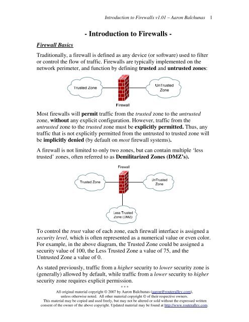
Traditionally, a firewall is defined as any device (or software) used <strong>to</strong> filter<br />
or control the flow of traffic. <strong>Firewalls</strong> are typically implemented on the<br />
network perimeter, and function by defining trusted and untrusted zones:<br />
Most firewalls will permit traffic from the trusted zone <strong>to</strong> the untrusted<br />
zone, without any explicit configuration. However, traffic from the<br />
untrusted zone <strong>to</strong> the trusted zone must be explicitly permitted. Thus, any<br />
traffic that is not explicitly permitted from the untrusted <strong>to</strong> trusted zone will<br />
be implicitly denied (by default on most firewall systems).<br />
A firewall is not limited <strong>to</strong> only two zones, but can contain multiple ‘less<br />
trusted’ zones, often referred <strong>to</strong> as Demilitarized Zones (DMZ’s).<br />
To control the trust value of each zone, each firewall interface is assigned a<br />
security level, which is often represented as a numerical value or even color.<br />
For example, in the above diagram, the Trusted Zone could be assigned a<br />
security value of 100, the Less Trusted Zone a value of 75, and the<br />
Untrusted Zone a value of 0.<br />
As stated previously, traffic from a higher security <strong>to</strong> lower security zone is<br />
(generally) allowed by default, while traffic from a lower security <strong>to</strong> higher<br />
security zone requires explicit permission.<br />
* * *<br />
All original material copyright © 2007 by Aaron Balchunas (aaron@routeralley.com),<br />
unless otherwise noted. All other material copyright © of their respective owners.<br />
This material may be copied and used freely, but may not be altered or sold without the expressed written<br />
consent of the owner of the above copyright. Updated material may be found at http://www.routeralley.com.<br />
1
Firewall Services<br />
<strong>Firewalls</strong> perform the following services:<br />
• Packet Filtering<br />
• Stateful Packet Inspection<br />
• Proxying<br />
• Network Address Translation (NAT)<br />
Each will be covered in some detail in this guide.<br />
Packet Filtering<br />
<strong>Introduction</strong> <strong>to</strong> <strong>Firewalls</strong> v1.01 – Aaron Balchunas<br />
Packet Filtering is one of the core services provided by firewalls. Packets<br />
can be filtered (permitted or denied) based on a wide range of criteria:<br />
• Source address<br />
• Destination address<br />
• Pro<strong>to</strong>col Type (IP, TCP, UDP, ICMP, ESP, etc.)<br />
• Source Port<br />
• Destination Port<br />
Packet filtering is implemented as a rule-list:<br />
Number Action Pro<strong>to</strong>col Source Add. Source Port Destination Add. Destination Port<br />
1. Deny TCP Any Any 172.16.1.5 666<br />
2. Permit IP Any Any 172.16.1.5 Any<br />
3. Permit TCP Any Any 172.16.1.1 443<br />
4. Permit TCP Any Any 172.16.1.1 80<br />
5. Permit TCP Any Any 172.16.1.10 25<br />
6. Deny TCP 66.1.1.5 Any 172.16.1.10 110<br />
7. Permit TCP Any Any 172.16.1.10 110<br />
The order of the rule-list is a critical consideration. The rule-list is always<br />
parsed from <strong>to</strong>p-<strong>to</strong>-bot<strong>to</strong>m. Thus, more specific rules should always be<br />
placed near the <strong>to</strong>p of the rule-list, otherwise they may be negated by a<br />
previous, more encompassing rule.<br />
Also, an implicit ‘deny any’ rule usually exists at the bot<strong>to</strong>m of a rule-list,<br />
which often can’t be removed. Thus, rule-lists that contain only deny<br />
statements will prevent all traffic.<br />
* * *<br />
All original material copyright © 2007 by Aaron Balchunas (aaron@routeralley.com),<br />
unless otherwise noted. All other material copyright © of their respective owners.<br />
This material may be copied and used freely, but may not be altered or sold without the expressed written<br />
consent of the owner of the above copyright. Updated material may be found at http://www.routeralley.com.<br />
2
Stateful Packet Inspection<br />
<strong>Introduction</strong> <strong>to</strong> <strong>Firewalls</strong> v1.01 – Aaron Balchunas<br />
Stateful packet inspection provides services beyond simple packetfiltering,<br />
by additionally tracking TCP or UDP sessions between devices.<br />
For example, stateful inspection can track connections that originate from<br />
the trusted network. This session information is kept in a state session table,<br />
which allows temporary holes <strong>to</strong> be opened in the firewall for the return<br />
traffic, which might otherwise be denied.<br />
Connections from the untrusted network <strong>to</strong> the trusted network are also<br />
moni<strong>to</strong>red, <strong>to</strong> prevent Denial of Service (DoS) attacks. If a high number of<br />
half-open sessions are detected, the firewall can be configured <strong>to</strong> drop the<br />
session (and even block the source), or send an alert message indicating an<br />
attack is occurring.<br />
A half-open TCP session indicates that the three-way handshake has not yet<br />
completed. A half-open UDP session indicates that no return UDP traffic<br />
has been detected. A large number of half-opened sessions will chew up<br />
resources, while preventing legitimate connections from being established.<br />
Proxy Services<br />
A proxy server, by definition, is used <strong>to</strong> make a request on behalf of another<br />
device. It essentially serves as a middle-man for communication between<br />
devices.<br />
This provides an element of security, by hiding the actual requesting source.<br />
All traffic will seem <strong>to</strong> be originated from the proxy itself.<br />
Traditionally, proxy servers were used <strong>to</strong> cache a local copy of requested<br />
external data. This improved performance in limited-bandwidth<br />
environments, allowing clients <strong>to</strong> request data from the proxy, instead of the<br />
actual external source.<br />
Other services that proxy servers can provide:<br />
• Logging<br />
• Content Filtering<br />
• Authentication<br />
* * *<br />
All original material copyright © 2007 by Aaron Balchunas (aaron@routeralley.com),<br />
unless otherwise noted. All other material copyright © of their respective owners.<br />
This material may be copied and used freely, but may not be altered or sold without the expressed written<br />
consent of the owner of the above copyright. Updated material may be found at http://www.routeralley.com.<br />
3
NAT (Network Address Translation)<br />
<strong>Introduction</strong> <strong>to</strong> <strong>Firewalls</strong> v1.01 – Aaron Balchunas<br />
The rapid growth of the Internet resulted in a shortage of IPv4 addresses. In<br />
response, the powers that be designated a specific subset of the IPv4 address<br />
space <strong>to</strong> be private, <strong>to</strong> temporarily alleviate this problem.<br />
A public address can be routed on the Internet. Thus, devices that should be<br />
Internet accessible (such web or email servers) must be configured with<br />
public addresses.<br />
A private address is only intended for use within an organization, and can<br />
never be routed on the internet. Three private addressing ranges were<br />
allocated, one for each IPv4 class:<br />
• Class A - 10.x.x.x<br />
• Class B - 172.16-31.x.x<br />
• Class C - 192.168.x.x<br />
NAT (Network Address Translation) is used <strong>to</strong> translate between private<br />
addresses and public addresses. NAT allows devices configured with a<br />
private address <strong>to</strong> be stamped with a public address, thus allowing those<br />
devices <strong>to</strong> communicate across the Internet.<br />
NAT is not restricted <strong>to</strong> just public-<strong>to</strong>-private address translations, though<br />
this is the most common application of NAT. NAT can perform a public-<strong>to</strong>public<br />
address translation, or a private-<strong>to</strong>-private address translation as well.<br />
NAT provides an additional benefit – hiding the specific addresses and<br />
addressing structure of the internal network.<br />
(Reference: http://www.cisco.com/en/US/tech/tk648/tk361/technologies_white_paper09186a0080194af8.shtml)<br />
* * *<br />
All original material copyright © 2007 by Aaron Balchunas (aaron@routeralley.com),<br />
unless otherwise noted. All other material copyright © of their respective owners.<br />
This material may be copied and used freely, but may not be altered or sold without the expressed written<br />
consent of the owner of the above copyright. Updated material may be found at http://www.routeralley.com.<br />
4
Types of NAT<br />
<strong>Introduction</strong> <strong>to</strong> <strong>Firewalls</strong> v1.01 – Aaron Balchunas<br />
NAT can be implemented using one of three methods:<br />
Static NAT – performs a static one-<strong>to</strong>-one translation between two<br />
addresses, or between a port on one address <strong>to</strong> a port on another address.<br />
Static NAT is most often used <strong>to</strong> assign a public address <strong>to</strong> a device behind a<br />
NAT-enabled firewall/router.<br />
Dynamic NAT – utilizes a pool of global addresses <strong>to</strong> dynamically translate<br />
the outbound traffic of clients behind a NAT-enabled device.<br />
NAT Overload or Port Address Translation (PAT) – translates the<br />
outbound traffic of clients <strong>to</strong> unique port numbers off of a single global<br />
address. PAT is necessary when the number of internal clients exceeds the<br />
available global addresses.<br />
NAT Terminology<br />
Specific terms are used <strong>to</strong> identify the various NAT addresses:<br />
• Inside Local – the specific IP address assigned <strong>to</strong> an inside host<br />
behind a NAT-enabled device (usually a private address).<br />
• Inside Global – the address that identifies an inside host <strong>to</strong> the<br />
outside world (usually a public address). Essentially, this is the<br />
dynamically or statically-assigned public address assigned <strong>to</strong> a private<br />
host.<br />
• Outside Global – the address assigned <strong>to</strong> an outside host (usually a<br />
public address).<br />
• Outside Local – the address that identifies an outside host <strong>to</strong> the<br />
inside network. Often, this is the same address as the Outside Global.<br />
However, it is occasionally necessary <strong>to</strong> translate an outside (usually<br />
public) address <strong>to</strong> an inside (usually private) address.<br />
For simplicity sake, it is generally acceptable <strong>to</strong> associate global addresses<br />
with public addresses, and local addresses with private addresses.<br />
However, remember that public-<strong>to</strong>-public and private-<strong>to</strong>-private translation<br />
is still possible. Inside hosts are within the local network, while outside<br />
hosts are external <strong>to</strong> the local network.<br />
* * *<br />
All original material copyright © 2007 by Aaron Balchunas (aaron@routeralley.com),<br />
unless otherwise noted. All other material copyright © of their respective owners.<br />
This material may be copied and used freely, but may not be altered or sold without the expressed written<br />
consent of the owner of the above copyright. Updated material may be found at http://www.routeralley.com.<br />
5
HostA<br />
10.1.1.10<br />
SRC Address = 10.1.1.10<br />
DST Address = 99.1.1.2<br />
NAT Terminology Example<br />
<strong>Introduction</strong> <strong>to</strong> <strong>Firewalls</strong> v1.01 – Aaron Balchunas<br />
Consider the above example. For a connection from HostA <strong>to</strong> HostB, the<br />
NAT addresses are identified as follows:<br />
• Inside Local Address - 10.1.1.10<br />
• Inside Global Address - 55.1.1.1<br />
• Outside Global Address – 99.1.1.2<br />
• Outside Local Address – 99.1.1.2<br />
HostA’s configured address is 10.1.1.10, and is identified as its Inside Local<br />
address. When HostA communicates with the Internet, it is stamped with<br />
<strong>Router</strong>A’s public address, using PAT. Thus, HostA’s Inside Global address<br />
will become 55.1.1.1.<br />
When HostA communicates with HostB, it will access HostB’s Outside<br />
Global address of 99.1.1.2. In this instance, the Outside Local address is also<br />
99.1.1.2. HostA is never aware of HostB’s configured address.<br />
It is possible <strong>to</strong> map an address from the local network (such as 10.1.1.5) <strong>to</strong><br />
the global address of the remote device (in this case, 99.1.1.2). This may be<br />
required if a legacy device exists that will only communicate with the local<br />
subnet. In this instance, the Outside Local address would be 10.1.1.5.<br />
10.1.1.1 55.1.1.1<br />
<strong>Router</strong>A<br />
NAT-Enabled<br />
SRC Address = 55.1.1.1:31092<br />
DST Address = 99.1.1.2<br />
Internet<br />
Static NAT Translation<br />
99.1.1.2 = 192.168.1.5<br />
99.1.1.1 192.168.1.1<br />
<strong>Router</strong>A<br />
NAT-Enabled<br />
SRC Address = 55.1.1.1:31092<br />
DST Address = 192.168.1.5<br />
The above example demonstrates how the source (SRC) and destination<br />
(DST) IP addresses within the Network-Layer header are translated by NAT.<br />
(Reference: http://www.cisco.com/warp/public/556/8.html)<br />
* * *<br />
All original material copyright © 2007 by Aaron Balchunas (aaron@routeralley.com),<br />
unless otherwise noted. All other material copyright © of their respective owners.<br />
This material may be copied and used freely, but may not be altered or sold without the expressed written<br />
consent of the owner of the above copyright. Updated material may be found at http://www.routeralley.com.<br />
6<br />
HostB<br />
192.168.1.5
Implementing a DMZ<br />
<strong>Introduction</strong> <strong>to</strong> <strong>Firewalls</strong> v1.01 – Aaron Balchunas<br />
As briefly described earlier, a DMZ is essentially a less trusted zone that<br />
sits between the trusted zone (generally the LAN) and the untrusted zone<br />
(generally the Internet). Devices that provide services <strong>to</strong> the untrusted world<br />
are generally placed in the DMZ, <strong>to</strong> provide separation from the trusted<br />
network.<br />
A single firewall with multiple ports can be used <strong>to</strong> implement a logical<br />
DMZ:<br />
A more secure DMZ (referred <strong>to</strong> as a screened subnet) utilizes multiple<br />
firewalls:<br />
* * *<br />
All original material copyright © 2007 by Aaron Balchunas (aaron@routeralley.com),<br />
unless otherwise noted. All other material copyright © of their respective owners.<br />
This material may be copied and used freely, but may not be altered or sold without the expressed written<br />
consent of the owner of the above copyright. Updated material may be found at http://www.routeralley.com.<br />
7