pdf datasheet - SiTime
pdf datasheet - SiTime
pdf datasheet - SiTime

You also want an ePaper? Increase the reach of your titles
YUMPU automatically turns print PDFs into web optimized ePapers that Google loves.
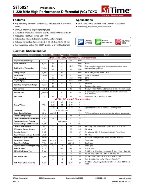
SiT5021 Preliminary<br />
1-220 MHz High Performance Differential (VC) TCXO<br />
Features<br />
• Any frequency between 1 MHz and 220 MHz accurate to 6 decimal<br />
places<br />
• LVPECL and LVDS output signaling types<br />
• 0.6ps RMS phase jitter (random) over 12 kHz to 20 MHz bandwidth<br />
• Frequency stability as low as ±2.5 PPM<br />
• Industrial and extended commercial temperature ranges<br />
• Industry-standard packages: 3.2 x 2.5, 5.0 x 3.2 and 7.0 x 5.0 mm<br />
• For frequencies higher than 220 MHz, refer to SiT5022 <strong>datasheet</strong><br />
Electrical Characteristics<br />
Applications<br />
The Smart Timing Choice<br />
The Smart Timing Choice<br />
• SATA, SAS, 10GB Ethernet, Fibre Channel, PCI-Express<br />
• Networking, broadband, instrumentation<br />
Parameter and Conditions Symbol Min. Typ. Max. Unit Condition<br />
LVPECL and LVDS, Common AC Characteristics<br />
Output Frequency Range f 1 – 220 MHz<br />
Initial Tolerance F_init -2 – 2 PPM At 25°C<br />
-2.5 – +2.5 PPM Over operating temperature range at rated nominal power<br />
Stability Over Temperature F_stab<br />
-5 – +5 PPM<br />
supply voltage and load.<br />
Supply Voltage F_vdd – 50 – PPB ±10% Vdd (±5% for Vdd = 1.8V)<br />
Output Load F_load – 0.1 – PPM 15 pF ±10% of load<br />
First year Aging<br />
-1.5 – +1.5 PPM 25°C<br />
F_aging<br />
10-year Aging -3.5 – +3.5 PPM 25°C<br />
-40 – +85 °C Industrial<br />
Operating Temperature Range T_use<br />
-20 – +70 °C Extended Commercial<br />
Start-up Time T_start – – 10 ms Measured from the time Vdd reaches its rated minimum value.<br />
Resume Time T_resume – 6 10 ms<br />
In Standby mode, measured from the time ST pin crosses<br />
50% threshold.<br />
Duty Cycle DC 45 – 55 % Contact <strong>SiTime</strong> for tighter duty cycle<br />
LVPECL, DC and AC Characteristics<br />
2.97 3.3 3.63 V<br />
Supply Voltage<br />
Vdd 2.25 2.5 2.75 V<br />
2.25 – 3.63 V Operates from 2.25V to 3.63V - XX ordering code<br />
Pull Range PR ±12.5, ±25, ±50 PPM<br />
Upper Control Voltage VC_U Vdd-0.1 – – V All Vdds. Voltage at which maximum deviation is guaranteed.<br />
Control Voltage Range VC_L – – 0.1 V<br />
Control Voltage Input Impedance Z_vc 100 – – k<br />
Frequency Change Polarity – Positive slope –<br />
Control Voltage -3dB Bandwidth V_BW – – 8 kHz<br />
Current Consumption Idd – – 69 mA Excluding Load Termination Current, Vdd = 3.3V or 2.5V<br />
OE Disable Supply Current I_OE – – 35 mA OE = Low<br />
Standby Current I_std – – 100 A For all Vdds, ST = GND, output is Weakly Pulled Down<br />
Output Disable Leakage Current I_leak – – 1 A OE = Low<br />
Maximum Output Current I-driver – – 30 mA Maximum average current drawn from OUT+ or OUT-<br />
Output High Voltage VOH Vdd-1.1 – Vdd-0.7 V See Figure 1<br />
Output Low Voltage VOL Vdd-1.9 – Vdd-1.5 V See Figure 1<br />
Output Differential Voltage Swing V_Swing 1.2 1.6 2.0 V See Figure 1<br />
Rise/Fall Time Tr, Tf – 300 500 ps 20% to 80%<br />
OE Enable/Disable Time T_oe – – 115 ns f = 220 MHz - For other frequencies, T_oe = 100ns + 3 period<br />
– 1.2 1.7 ps f = 100 MHz, Vdd = 3.3V, 2.5V or 2.5V to 3.3V<br />
RMS Period Jitter<br />
T_jitt – 1.2 1.7 ps f = 156.25 MHz, Vdd = 3.3V, 2.5V or 2.5V to 3.3V<br />
– 1.2 1.7 ps f = 212.5 MHz, Vdd =3.3V, 2.5V or 2.5V to 3.3V<br />
RMS Phase Jitter (random) T_phj – 0.6 0.85 ps<br />
f = 156.25 MHz, Integration bandwidth = 12 kHz to 20 MHz, all<br />
Vdds<br />
<strong>SiTime</strong> Corporation 990 Almanor Avenue Sunnyvale, CA 94085 (408) 328-4400 www.sitime.com<br />
Rev. 1.2 Revised August 20, 2013
SiT5021<br />
1-220 MHz High Performance Differential (VC) TCXO<br />
The Smart Timing Choice<br />
The Smart Timing Choice<br />
Electrical Characteristics (continued)<br />
Parameter and Conditions Symbol Min. Typ. Max. Unit Condition<br />
LVDS, DC and AC Characteristics<br />
Vdd 2.97 3.3 3.63 V<br />
Supply Voltage<br />
2.25 2.5 2.75 V<br />
1.71 1.8 1.89 V<br />
2.25 – 3.63 V Operates from 2.25V to 3.63V - XX ordering code<br />
Current Consumption Idd – 47 55 mA Excluding Load Termination Current, Vdd = 3.3V or 2.5V<br />
OE Disable Supply Current I_OE – – 35 mA OE = Low<br />
Standby Current I_std – – 100 A For all Vdds, ST = GND, output is Weakly Pulled Down<br />
Output Disable Leakage Current I_leak – – 1 A OE = Low<br />
Differential Output Voltage VOD 200 350 500 mV See Figure 4<br />
VOD Magnitude Change VOD – – 50 mV See Figure 4<br />
Offset Voltage VOS 1.125 1.2 1.375 V See Figure 4<br />
VOS Magnitude Change VOS – – 50 mV See Figure 4<br />
Rise/Fall Time Tr, Tf – 495 600 ps 20% to 80%<br />
OE Enable/Disable Time T_oe – – 115 ns f = 220 MHz - For other frequencies, T_oe = 100ns + 3 period<br />
RMS Period Jitter<br />
RMS Phase Jitter (random)<br />
Pin Description<br />
T_jitt – 1.2 1.7 ps f = 100 MHz, VDD = 3.3V, 2.5V or 2.5V to 3.3V<br />
– 1.2 1.7 ps f = 156.25 MHz, VDD = 3.3V, 2.5V or 2.5V to 3.3V<br />
– 1.2 1.7 ps f = 212.5 MHz, VDD = 3.3V, 2.5V or 2.5V to 3.3V<br />
T_phj – 0.6 0.85 ps f = 156.25 MHz, Integration bandwidth = 12 kHz to 20 MHz, all<br />
Vdds<br />
Pin Map Functionality<br />
V control<br />
Output Enable<br />
Voltage control.<br />
H or Open [1] : specified frequency output.<br />
L: output is high impedance. Only output driver is disabled.<br />
1 VC/OE/ST/NC<br />
H or Open [1] : specified frequency output.<br />
Standby L: output is low (weak pull down). Device goes to sleep mode.<br />
Supply current reduces to I_std.<br />
NC No connect (Receiver OFF).<br />
2 NC NA Do not connect; Leave it floating.<br />
3 GND Power VDD power supply ground.<br />
4 OUT+ Output Oscillator output.<br />
5 OUT- Output Complementary oscillator output.<br />
6 VDD Power Power supply voltage.<br />
Top View<br />
VC/OE/ST/NC 1 6<br />
NC 2<br />
5<br />
GND 3<br />
4<br />
VDD<br />
OUT-<br />
OUT+<br />
Note:<br />
1. A pull-up resistor of
SiT5021<br />
1-220 MHz High Performance Differential (VC) TCXO<br />
Termination Diagrams<br />
The Smart Timing Choice<br />
The Smart Timing Choice<br />
LVPECL:<br />
VDD<br />
OUT+<br />
Z0 = 50 <br />
D+<br />
Drive Device<br />
Receiver Device<br />
OUT-<br />
Z0 = 50 <br />
D-<br />
50 <br />
50 <br />
VTT = VDD – 2.0 V<br />
Figure 1. LVPECL Typical Termination<br />
VDD<br />
R1 = 100 to 150 <br />
100 nF<br />
OUT+<br />
Z0 = 50 <br />
D+<br />
Drive Device<br />
OUT-<br />
Z0 = 50 <br />
100 nF<br />
D-<br />
Receiver Device<br />
R1<br />
R1<br />
50 50 <br />
VTT<br />
Figure 2. LVPECL AC Coupled Termination<br />
VDD<br />
VDD = 3.3V => R1 = R3 = 133 and<br />
R2 = R4 = 82 <br />
VDD = 2.5V => R1 = R3 = 250 and<br />
R2 = R4 = 62.5 <br />
VDD<br />
R1<br />
R3<br />
OUT+<br />
Z0 = 50 <br />
D+<br />
Drive Device<br />
Receiver<br />
Device<br />
OUT-<br />
Z0 = 50 <br />
D-<br />
R2<br />
R4<br />
Figure 3. LVPECL with Thevenin Typical Termination<br />
Rev. 1.2 Page 3 of 6 www.sitime.com
SiT5021<br />
1-220 MHz High Performance Differential (VC) TCXO<br />
LVDS:<br />
The Smart Timing Choice<br />
The Smart Timing Choice<br />
VDD<br />
OUT+<br />
Z0 = 50 <br />
D+<br />
Drive Device<br />
100 <br />
Receiver Device<br />
OUT-<br />
Z0 = 50 <br />
D-<br />
Figure 4. LVDS Single Termination (Load Terminated)<br />
Rev. 1.2 Page 4 of 6 www.sitime.com
SiT5021<br />
1-220 MHz High Performance Differential (VC) TCXO<br />
Dimensions and Patterns<br />
The Smart Timing Choice<br />
The Smart Timing Choice<br />
Package Size – Dimensions (Unit: mm) [2] Recommended Land Pattern (Unit: mm) [3]<br />
3.2 x 2.5x 0.75 mm<br />
6<br />
5<br />
4 6<br />
5<br />
4<br />
YXXXX<br />
1<br />
2<br />
3<br />
3<br />
2 1<br />
5.0 x 3.2 x 0.75 mm<br />
#6<br />
#5<br />
#4<br />
#4 #5 #6<br />
YXXXX<br />
1.20<br />
#1 #2 #3<br />
#3<br />
#2<br />
#1<br />
0.75±0.05<br />
7.0 x 5.0x 0.90 mm<br />
7.0±0.10<br />
#6 #5<br />
#4<br />
#4<br />
5.08<br />
#5<br />
#6<br />
5.08<br />
YXXXX<br />
5.0±0.10<br />
2.60<br />
1.10<br />
3.80<br />
#1 #2<br />
#3<br />
0.90 ±0.10<br />
#3<br />
#2<br />
#1<br />
1.40<br />
1.60<br />
1.60<br />
Notes:<br />
2. Top Marking: Y denotes manufacturing origin and XXXX denotes manufacturing lot number. The value of “Y” will depend on the assembly location of the device.<br />
3. A capacitor of value 0.1 µF between Vdd and GND is recommended.<br />
Rev. 1.2 Page 5 of 6 www.sitime.com
SiT5021<br />
1-220 MHz High Performance Differential (VC) TCXO<br />
Ordering Information<br />
The Smart Timing Choice<br />
The Smart Timing Choice<br />
SiT5021AC -1CD-33VQ123.123456T<br />
Part Family<br />
“SiT5021”<br />
Revision Letter<br />
“A” is the revision of Silicon<br />
Temperature Range<br />
“C” Extended Commercial, -20 to 70°C<br />
“I” Industrial, -40 to 85°C<br />
Signalling Type<br />
“1” = LVPECL<br />
“2” = LVDS<br />
Package Size<br />
“B” 3.2 x 2.5 mm<br />
“C” 5.0 x 3.2 mm<br />
“D” 7.0 x 5.0 mm<br />
Frequency Stability<br />
“D” for ±2.5 PPM<br />
“E” for ±5.0 PPM<br />
Packaging:<br />
“T” for Tape & Reel (3 Ku Reel)<br />
“Y” for Tape & Reel (1 Ku Reel)<br />
Blank for Bulk<br />
Frequency<br />
1.000000 MHz to<br />
220.000000 MHz<br />
Pull Range Options<br />
“-” for No Pull<br />
“Q” for ±12.5 PPM<br />
“M” for ±25 PPM<br />
“B” for ±50 PPM<br />
Feature Pin (pin 1)<br />
“V” for Voltage Control<br />
“E” for Output Enable<br />
“S” for Standby<br />
“N” for No Connect<br />
Supply Voltage<br />
“18” for 1.8V ±5% (LVDS only)<br />
“25” for 2.5V ±10%<br />
“33” for 3.3V ±10%<br />
“XX” for 2.5 to 3.3V ±10%<br />
© <strong>SiTime</strong> Corporation 2013. The information contained herein is subject to change at any time without notice. <strong>SiTime</strong> assumes no responsibility or liability for any loss, damage or defect of a<br />
Product which is caused in whole or in part by (i) use of any circuitry other than circuitry embodied in a <strong>SiTime</strong> product, (ii) misuse or abuse including static discharge, neglect or accident, (iii)<br />
unauthorized modification or repairs which have been soldered or altered during assembly and are not capable of being tested by <strong>SiTime</strong> under its normal test conditions, or (iv) improper<br />
installation, storage, handling, warehousing or transportation, or (v) being subjected to unusual physical, thermal, or electrical stress.<br />
Disclaimer: <strong>SiTime</strong> makes no warranty of any kind, express or implied, with regard to this material, and specifically disclaims any and all express or implied warranties, either in fact or by<br />
operation of law, statutory or otherwise, including the implied warranties of merchantability and fitness for use or a particular purpose, and any implied warranty arising from course of dealing or<br />
usage of trade, as well as any common-law duties relating to accuracy or lack of negligence, with respect to this material, any <strong>SiTime</strong> product and any product documentation. Products sold by<br />
<strong>SiTime</strong> are not suitable or intended to be used in a life support application or component, to operate nuclear facilities, or in other mission critical applications where human life may be involved<br />
or at stake. All sales are made conditioned upon compliance with the critical uses policy set forth below.<br />
CRITICAL USE EXCLUSION POLICY<br />
BUYER AGREES NOT TO USE SITIME'S PRODUCTS FOR ANY APPLICATION OR IN ANY COMPONENTS USED IN LIFE SUPPORT DEVICES OR TO OPERATE NUCLEAR FACILITIES<br />
OR FOR USE IN OTHER MISSION-CRITICAL APPLICATIONS OR COMPONENTS WHERE HUMAN LIFE OR PROPERTY MAY BE AT STAKE.<br />
<strong>SiTime</strong> owns all rights, title and interest to the intellectual property related to <strong>SiTime</strong>'s products, including any software, firmware, copyright, patent, or trademark. The sale of <strong>SiTime</strong> products<br />
does not convey or imply any license under patent or other rights. <strong>SiTime</strong> retains the copyright and trademark rights in all documents, catalogs and plans supplied pursuant to or ancillary to the<br />
sale of products or services by <strong>SiTime</strong>. Unless otherwise agreed to in writing by <strong>SiTime</strong>, any reproduction, modification, translation, compilation, or representation of this material shall be strictly<br />
prohibited.<br />
Rev. 1.2 Page 6 of 6 www.sitime.com
The Smart Timing Choice<br />
The Smart Timing Choice<br />
Supplemental Information<br />
The Supplemental Information section is not part of the <strong>datasheet</strong> and is for informational purposes only.<br />
<strong>SiTime</strong> Corporation 990 Almanor Avenue Sunnyvale, CA 94085 (408) 328-4400 www.sitime.com
The Smart Timing Choice<br />
The Smart Timing Choice<br />
Silicon MEMS Outperforms Quartz<br />
<strong>SiTime</strong> Corporation 990 Almanor Avenue Sunnyvale, CA 94085 (408) 328-4400 www.sitime.com<br />
Silicon MEMS Outperforms Quartz Rev. 1.0 Revised January 16, 2013
Silicon MEMS Outperforms Quartz<br />
The Smart Timing Choice<br />
The Smart Timing Choice<br />
Best Reliability<br />
Silicon is inherently more reliable than quartz. Unlike quartz<br />
suppliers, <strong>SiTime</strong> has in-house MEMS and analog CMOS<br />
expertise, which allows <strong>SiTime</strong> to develop the most reliable<br />
products. Figure 1 shows a comparison with quartz<br />
technology.<br />
Why is <strong>SiTime</strong> Best in Class:<br />
• <strong>SiTime</strong>’s MEMS resonators are vacuum sealed using an<br />
advanced Epi-Seal process, which eliminates foreign<br />
particles and improves long term aging and reliability<br />
• World-class MEMS and CMOS design expertise<br />
Best Electro Magnetic Susceptibility (EMS)<br />
<strong>SiTime</strong>’s oscillators in plastic packages are up to 54 times<br />
more immune to external electromagnetic fields than quartz<br />
oscillators as shown in Figure 3.<br />
Why is <strong>SiTime</strong> Best in Class:<br />
• Internal differential architecture for best common mode<br />
noise rejection<br />
• Electrostatically driven MEMS resonator is more immune<br />
to EMS<br />
<strong>SiTime</strong><br />
IDT (Fox)<br />
Epson<br />
TXC<br />
Pericom<br />
Mean Time Between Failure (Million Hours)<br />
16<br />
14<br />
38<br />
28<br />
<strong>SiTime</strong><br />
20X Better<br />
500<br />
0 200 400 600<br />
Average Spurs (dB)<br />
- 30<br />
- 40<br />
- 50<br />
- 60<br />
- 70<br />
- 80<br />
- 90<br />
<strong>SiTime</strong> vs Quartz<br />
Electro Magnetic Susceptibility (EMS)<br />
- 39 - 40<br />
- 42 - 43<br />
- 45<br />
<strong>SiTime</strong><br />
54X Better<br />
- 73<br />
Kyocera Epson TXC CW SiLabs <strong>SiTime</strong><br />
Figure 1. Reliability Comparison [1]<br />
Best Aging<br />
Unlike quartz, MEMS oscillators have excellent long term<br />
aging performance which is why every new <strong>SiTime</strong> product<br />
specifies 10-year aging. A comparison is shown in Figure 2.<br />
Why is <strong>SiTime</strong> Best in Class:<br />
• <strong>SiTime</strong>’s MEMS resonators are vacuum sealed using an<br />
advanced Epi-Seal process, which eliminates foreign<br />
particles and improves long term aging and reliability<br />
• Inherently better immunity of electrostatically driven<br />
MEMS resonator<br />
Figure 3. Electro Magnetic Susceptibility (EMS) [3]<br />
Best Power Supply Noise Rejection<br />
<strong>SiTime</strong>’s MEMS oscillators are more resilient against noise on<br />
the power supply. A comparison is shown in Figure 4.<br />
Why is <strong>SiTime</strong> Best in Class:<br />
• On-chip regulators and internal differential architecture for<br />
common mode noise rejection<br />
• Best analog CMOS design expertise<br />
10<br />
<strong>SiTime</strong> MEMS vs. Quartz Aging<br />
<strong>SiTime</strong> MEMS Oscillator<br />
Quartz Oscillator<br />
5.0<br />
Power Supply Noise Rejection<br />
SiTIme NDK Epson Kyocera<br />
Additive Integrated Phase Jitter per mVp-p<br />
Injected Noise (ps/mv)<br />
8<br />
8.0<br />
4.0<br />
Aging (±PPM)<br />
6<br />
4<br />
2<br />
0<br />
1.5<br />
1-Year<br />
3.0<br />
<strong>SiTime</strong><br />
2X Better<br />
3.5<br />
10-Year<br />
3.0<br />
2.0<br />
1.0<br />
<strong>SiTime</strong> <strong>SiTime</strong><br />
3X Better<br />
0.0<br />
10 100 1,000 10,000<br />
Power Supply Noise Frequency (kHz)<br />
Figure 2. Aging Comparison [2]<br />
Figure 4. Power Supply Noise Rejection [4]<br />
Silicon MEMS Outperforms Quartz Rev. 1.0 www.sitime.com
Silicon MEMS Outperforms Quartz<br />
The Smart Timing Choice<br />
The Smart Timing Choice<br />
Best Vibration Robustness<br />
High-vibration environments are all around us. All electronics,<br />
from handheld devices to enterprise servers and storage<br />
systems are subject to vibration. Figure 5 shows a comparison<br />
of vibration robustness.<br />
Why is <strong>SiTime</strong> Best in Class:<br />
• The moving mass of <strong>SiTime</strong>’s MEMS resonators is up to<br />
3000 times smaller than quartz<br />
• Center-anchored MEMS resonator is the most robust<br />
design<br />
Best Shock Robustness<br />
<strong>SiTime</strong>’s oscillators can withstand at least 50,000 g shock.<br />
They all maintain their electrical performance in operation<br />
during shock events. A comparison with quartz devices is<br />
shown in Figure 6.<br />
Why is <strong>SiTime</strong> Best in Class:<br />
• The moving mass of <strong>SiTime</strong>’s MEMS resonators is up to<br />
3000 times smaller than quartz<br />
• Center-anchored MEMS resonator is the most robust<br />
design<br />
Vibration Sensitivity (ppb/g)<br />
100.00<br />
10.00<br />
1.00<br />
0.10<br />
Vibration Sensitivity vs. Frequency<br />
<strong>SiTime</strong> TXC Epson Connor Winfield Kyocera SiLabs<br />
<strong>SiTime</strong><br />
Up to 30x<br />
Better<br />
10 100 1000<br />
Vibration Frequency (Hz)<br />
Peak Frequency Deviation (PPM)<br />
16<br />
14<br />
12<br />
10<br />
8<br />
6<br />
4<br />
2<br />
0<br />
14.3<br />
Differential XO Shock Robustness - 500 g<br />
12.6<br />
3.9<br />
2.9<br />
2.5<br />
<strong>SiTime</strong><br />
Up to 25x<br />
Better<br />
0.6<br />
Kyocera Epson TXC CW SiLabs <strong>SiTime</strong><br />
Figure 5. Vibration Robustness [5]<br />
Figure 6. Shock Robustness [6]<br />
Notes:<br />
1. Data Source: Reliability documents of named companies.<br />
2. Data source: <strong>SiTime</strong> and quartz oscillator devices <strong>datasheet</strong>s.<br />
3. Test conditions for Electro Magnetic Susceptibility (EMS):<br />
• According to IEC EN61000-4.3 (Electromagnetic compatibility standard)<br />
• Field strength: 3V/m<br />
• Radiated signal modulation: AM 1 kHz at 80% depth<br />
• Carrier frequency scan: 80 MHz – 1 GHz in 1% steps<br />
• Antenna polarization: Vertical<br />
• DUT position: Center aligned to antenna<br />
Devices used in this test:<br />
<strong>SiTime</strong>, SiT9120AC-1D2-33E156.250000 - MEMS based - 156.25 MHz<br />
Epson, EG-2102CA 156.2500M-PHPAL3 - SAW based - 156.25 MHz<br />
TXC, BB-156.250MBE-T - 3rd Overtone quartz based - 156.25 MHz<br />
Kyocera, KC7050T156.250P30E00 - SAW based - 156.25 MHz<br />
Connor Winfield (CW), P123-156.25M - 3rd overtone quartz based - 156.25 MHz<br />
SiLabs, Si590AB-BDG - 3rd overtone quartz based - 156.25 MHz<br />
4. 50 mV pk-pk Sinusoidal voltage.<br />
Devices used in this test:<br />
<strong>SiTime</strong>, SiT8208AI-33-33E-25.000000, MEMS based - 25 MHz<br />
NDK, NZ2523SB-25.6M - quartz based - 25.6 MHz<br />
Kyocera, KC2016B25M0C1GE00 - quartz based - 25 MHz<br />
Epson, SG-310SCF-25M0-MB3 - quartz based - 25 MHz<br />
5. Devices used in this test: same as EMS test stated in Note 3.<br />
6. Test conditions for shock test:<br />
• MIL-STD-883F Method 2002<br />
• Condition A: half sine wave shock pulse, 500-g, 1ms<br />
• Continuous frequency measurement in 100 μs gate time for 10 seconds<br />
Devices used in this test: same as EMS test stated in Note 3<br />
7. Additional data, including setup and detailed results, is available upon request to qualified customers. Please contact productsupport@sitime.com.<br />
Silicon MEMS Outperforms Quartz Rev. 1.0 www.sitime.com
Document Feedback Form<br />
The Smart Timing Choice<br />
The Smart Timing Choice<br />
<strong>SiTime</strong> values your input in improving our documentation. Click here for our online feedback form or fill out and email the form<br />
below to productsupport@sitime.com.<br />
1. Does the Electrical Characteristics table provide complete information Yes No<br />
If No, what parameters are missing<br />
_________________________________________________________________________________________________<br />
2. Is the organization of this document easy to follow Yes No<br />
If “No,” please suggest improvements that we can make:<br />
_________________________________________________________________________________________________<br />
3. Is there any application specific information that you would like to see in this document (Check all that apply)<br />
EMI Termination recommendations Shock and vibration performance Other<br />
If “Other,” please specify:<br />
_________________________________________________________________________________________________<br />
4. Are there any errors in this document Yes No<br />
If “Yes”, please specify (what and where):<br />
_________________________________________________________________________________________________<br />
5. Do you have additional recommendations for this document<br />
_________________________________________________________________________________________________<br />
Name<br />
Title<br />
________________________________________________________________________________<br />
________________________________________________________________________________<br />
Company _________________________________________________________________________________________<br />
Address<br />
_________________________________________________________________________________________<br />
City / State or Province / Postal Code / Country ___________________________________________________________<br />
Telephone __________________________________<br />
Application ________________________________________________________________________________________<br />
Would you like a reply Yes No<br />
Thank you for your feedback. Please click the email icon in your Adobe Reader tool bar and send to productsupport@sitime.com.<br />
Or you may use our online feedback form.<br />
Feedback Form Rev. 1.0 www.sitime.com