U 15 - VAHLE, Inc
U 15 - VAHLE, Inc
U 15 - VAHLE, Inc

You also want an ePaper? Increase the reach of your titles
YUMPU automatically turns print PDFs into web optimized ePapers that Google loves.
19 12<br />
INSULATED CONDUCTORS U <strong>15</strong> – U 25 – U 35<br />
General<br />
<strong>VAHLE</strong> insulated conductors U <strong>15</strong>, U 25 and U 35 are designed<br />
in accordance with today’s international safety requirements.<br />
They fully meet VDE 0100 and are finger safe to VDE 0470, part<br />
1, protection code IP 23.<br />
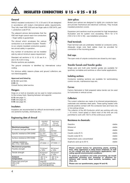
The adjacent picture demonstrates that the<br />
VDE test finger cannot reach live conductors<br />
– finger safety is guaranteed.<br />
The shroud which envelopes the various<br />
conductors is an excellent insulator. Therefore<br />
our unipole insulated conductors guarantee<br />
utmost safety in operation.<br />
Any number of conductors can be installed<br />
side by side at minimum space requirement.<br />
Standard rail sections U <strong>15</strong>, U 25 are 6 m<br />
and U 35, 6.25 m long.<br />
Shorter sections are available.<br />
The ground conductor is identified by international colour<br />
coding.<br />
For obvious safety reasons phase and ground collectors are<br />
not interchangeable.<br />
Approved and listed by<br />
U <strong>15</strong>: SEV and CSA,<br />
U 25: UL<br />
Consult factory label service.<br />
Hangers<br />
Snap-on or bolt-on brackets can be used to install conductors<br />
to the runway track. Spacing between rail supports:<br />
U <strong>15</strong>: see page 11,<br />
U 25: see page 23,<br />
U 35: see page 40.<br />
Insulators<br />
Insulators are recommended for difficult environmental conditions<br />
(extreme humidity, chemicals etc.)<br />
Engineering data of shroud<br />
Electrical properties:<br />
Di-electric strength DIN 53481<br />
Specific resistance DIN 53482<br />
Surface resistance DIN 53482<br />
Leakage resistance<br />
IEC 1112 / VDE 0303<br />
Mechanical properties<br />
Flexible strength<br />
Tensile strength<br />
Ambient<br />
temperature<br />
Flame test proof per<br />
DIN 4102<br />
part 1<br />
standard<br />
shroud<br />
color green<br />
30-40<br />
kV/mm<br />
5 x 10 <strong>15</strong><br />
Ohm/cm<br />
10 13<br />
Ohm<br />
CTI 600-1.1<br />
75 N/mm 2<br />
± 10%<br />
50 N/mm 2<br />
± 10%<br />
–30° C to<br />
+55° C<br />
high temp.<br />
shroud<br />
color gray<br />
45<br />
kV/mm<br />
5 x 10 17<br />
Ohm/cm<br />
10 <strong>15</strong><br />
Ohm<br />
CTI 600-1.1<br />
95 N/mm 2<br />
± 10%<br />
50 N/mm 2<br />
± 10%<br />
–30° C to<br />
+85° C<br />
class B1<br />
no flaming particles,<br />
self-extinguishing<br />
Joint splices<br />
Bolted joint splices are designed to rigidly join conductor bars<br />
and provide mechanical and electrical continuity. They include<br />
insulated protection covers.<br />
Expansion joint sections must be provided for high temperature<br />
fluctuation and for system runs exceeding 100 m for U <strong>15</strong><br />
(<strong>15</strong>0 m for U 25 / U 35) – see installation procedure.<br />
Feed terminals<br />
Feed terminal sets are preferably installed at conductor joints.<br />
Adequate single core feed cables must be provided for<br />
connection of the incoming power.<br />
End caps<br />
The open ends of unipole conductors are closed by end caps.<br />
Transfer funnels and Transfer guides<br />
Single pole and multi pole transfer guides are available for<br />
spurlines, turntables and switches or other tranfer applications.<br />
Isolating sections<br />
Conductor isolating sections are available for sectionalizing<br />
control circuits, maintenance bays etc.<br />
Curves<br />
Factory fabricated or field prepared radius bends can be used<br />
for horizontal or vertical curves.<br />
Collectors<br />
The current collectors are made of re-inforced polyamide/polycarbonate<br />
and stainless steel parts. These spring loaded units<br />
provide positive contact with the conductor bars and have one<br />
or two pickup-shoes.<br />
The collector of the AE-Conductor which are working with only<br />
> 10 m/min. travel speed or stand most of the time are only<br />
permitted to work with <strong>15</strong>0 % of the continuous current.<br />
Resistance to chemicals:<br />
Gasoline<br />
Mineral oil<br />
Grease<br />
Caustic soda 25 %<br />
Caustic soda 50 %<br />
Hydrochloric acid, concentrated<br />
Sulphuric acid up to 50 %<br />
stable<br />
stable<br />
stable<br />
stable<br />
stable<br />
stable<br />
stable<br />
Please consult factory for galvanizing plants, pickling<br />
lines, other aggressive or deep freeze ambients, as well<br />
as low voltage and data transmission applications, indicating<br />
special environmental conditions.<br />
To speed up quotations and order processing, we would<br />
appreciate receiving your drawings or sketches for<br />
systems with curves, dead sections, turntables, switches,<br />
etc.<br />
Please use our questionnaire, pages 44 and 45.<br />
4