U 15 - VAHLE, Inc
U 15 - VAHLE, Inc
U 15 - VAHLE, Inc

Create successful ePaper yourself
Turn your PDF publications into a flip-book with our unique Google optimized e-Paper software.
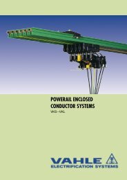
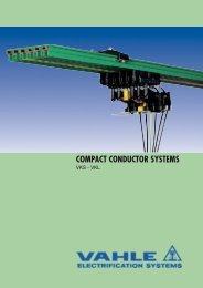
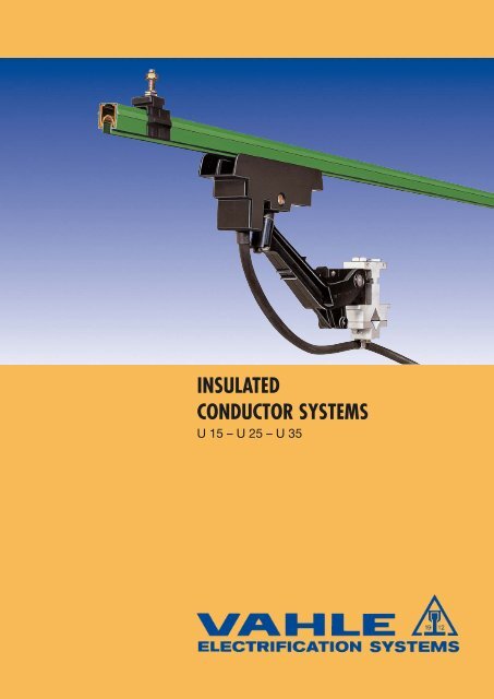
INSULATED<br />
CONDUCTOR SYSTEMS<br />
U <strong>15</strong> – U 25 – U 35
19 12<br />
INSULATED CONDUCTORS U <strong>15</strong> – U 25 – U 35<br />
Index U <strong>15</strong> U 25 U 35<br />
Page Page Page<br />
Basic description 4 4 4<br />
Selection of conductors 5 5 5<br />
Insulated conductors 5 23 34<br />
Joint splices 6 23 34<br />
Expansion sections 6 24 35<br />
Feed terminals 6 24 35<br />
Locating clamps 7 24 36<br />
Insulated hangers 7 25 36<br />
Rail holders 7 25 36<br />
Insulators 7 25 36<br />
Compact hangers, bracket profiles 7 26 –<br />
Attachment hardware 8 26 –<br />
Transfer guides 8, 9 26 37<br />
Sectionalizing 9 25 34<br />
End caps 9 25 34<br />
Transfer funnels 10, 11 28 –<br />
Collectors 11 – 14 27 38, 39<br />
Connecting cables <strong>15</strong> – –<br />
Collector brackets, Cable attachment clamp 16 28 38<br />
Contact grease <strong>15</strong> 28 36<br />
Components for collectors, Spare parts 16 – 18 29 – 31 40, 41<br />
Brush wear indicator 19 – –<br />
Brackets, Snap-on brackets, Mounting brackets 20 33 –<br />
Examples for ordering, Arrangement 21 32 42<br />
Installation tools 22 – –<br />
Earthing spider system – 43 43<br />
Questionnaire 44, 45 44, 45 44, 45<br />
Application photos 2, 5<br />
Collector rings with insulated conductors see leaflet No. 102.<br />
2
INSULATED CONDUCTORS U <strong>15</strong> – U 25 – U 35<br />
19 12<br />
GENERAL<br />
SELECTION OF CONDUCTORS<br />
ENGINEERING DATA<br />
Pages 4 – 5<br />
U <strong>15</strong><br />
For light cranes and hoists/elevators, self-propelled monorail<br />
carriers, automated storage and retrieval systems, assembly<br />
and test tracks, motor powered gates and doors, for all kinds<br />
of data and signal transmission, etc<br />
Ampacity up to 100 A<br />
Pages 5 – 22<br />
U 25<br />
For bridge- and portal crane electrification, stacker cranes,<br />
heavy monorail systems, amusement & rapid transit rides,<br />
construction- and maintenance lifts etc. – Ampacity up to<br />
450 A<br />
Pages 23 – 33<br />
U 35<br />
Applications as U 25;<br />
however for heavy duty – Ampacity up to 1250 A<br />
Pages 34 – 42<br />
Questionnaire<br />
Pages 44, 45<br />
3
19 12<br />
INSULATED CONDUCTORS U <strong>15</strong> – U 25 – U 35<br />
General<br />
<strong>VAHLE</strong> insulated conductors U <strong>15</strong>, U 25 and U 35 are designed<br />
in accordance with today’s international safety requirements.<br />
They fully meet VDE 0100 and are finger safe to VDE 0470, part<br />
1, protection code IP 23.<br />
The adjacent picture demonstrates that the<br />
VDE test finger cannot reach live conductors<br />
– finger safety is guaranteed.<br />
The shroud which envelopes the various<br />
conductors is an excellent insulator. Therefore<br />
our unipole insulated conductors guarantee<br />
utmost safety in operation.<br />
Any number of conductors can be installed<br />
side by side at minimum space requirement.<br />
Standard rail sections U <strong>15</strong>, U 25 are 6 m<br />
and U 35, 6.25 m long.<br />
Shorter sections are available.<br />
The ground conductor is identified by international colour<br />
coding.<br />
For obvious safety reasons phase and ground collectors are<br />
not interchangeable.<br />
Approved and listed by<br />
U <strong>15</strong>: SEV and CSA,<br />
U 25: UL<br />
Consult factory label service.<br />
Hangers<br />
Snap-on or bolt-on brackets can be used to install conductors<br />
to the runway track. Spacing between rail supports:<br />
U <strong>15</strong>: see page 11,<br />
U 25: see page 23,<br />
U 35: see page 40.<br />
Insulators<br />
Insulators are recommended for difficult environmental conditions<br />
(extreme humidity, chemicals etc.)<br />
Engineering data of shroud<br />
Electrical properties:<br />
Di-electric strength DIN 53481<br />
Specific resistance DIN 53482<br />
Surface resistance DIN 53482<br />
Leakage resistance<br />
IEC 1112 / VDE 0303<br />
Mechanical properties<br />
Flexible strength<br />
Tensile strength<br />
Ambient<br />
temperature<br />
Flame test proof per<br />
DIN 4102<br />
part 1<br />
standard<br />
shroud<br />
color green<br />
30-40<br />
kV/mm<br />
5 x 10 <strong>15</strong><br />
Ohm/cm<br />
10 13<br />
Ohm<br />
CTI 600-1.1<br />
75 N/mm 2<br />
± 10%<br />
50 N/mm 2<br />
± 10%<br />
–30° C to<br />
+55° C<br />
high temp.<br />
shroud<br />
color gray<br />
45<br />
kV/mm<br />
5 x 10 17<br />
Ohm/cm<br />
10 <strong>15</strong><br />
Ohm<br />
CTI 600-1.1<br />
95 N/mm 2<br />
± 10%<br />
50 N/mm 2<br />
± 10%<br />
–30° C to<br />
+85° C<br />
class B1<br />
no flaming particles,<br />
self-extinguishing<br />
Joint splices<br />
Bolted joint splices are designed to rigidly join conductor bars<br />
and provide mechanical and electrical continuity. They include<br />
insulated protection covers.<br />
Expansion joint sections must be provided for high temperature<br />
fluctuation and for system runs exceeding 100 m for U <strong>15</strong><br />
(<strong>15</strong>0 m for U 25 / U 35) – see installation procedure.<br />
Feed terminals<br />
Feed terminal sets are preferably installed at conductor joints.<br />
Adequate single core feed cables must be provided for<br />
connection of the incoming power.<br />
End caps<br />
The open ends of unipole conductors are closed by end caps.<br />
Transfer funnels and Transfer guides<br />
Single pole and multi pole transfer guides are available for<br />
spurlines, turntables and switches or other tranfer applications.<br />
Isolating sections<br />
Conductor isolating sections are available for sectionalizing<br />
control circuits, maintenance bays etc.<br />
Curves<br />
Factory fabricated or field prepared radius bends can be used<br />
for horizontal or vertical curves.<br />
Collectors<br />
The current collectors are made of re-inforced polyamide/polycarbonate<br />
and stainless steel parts. These spring loaded units<br />
provide positive contact with the conductor bars and have one<br />
or two pickup-shoes.<br />
The collector of the AE-Conductor which are working with only<br />
> 10 m/min. travel speed or stand most of the time are only<br />
permitted to work with <strong>15</strong>0 % of the continuous current.<br />
Resistance to chemicals:<br />
Gasoline<br />
Mineral oil<br />
Grease<br />
Caustic soda 25 %<br />
Caustic soda 50 %<br />
Hydrochloric acid, concentrated<br />
Sulphuric acid up to 50 %<br />
stable<br />
stable<br />
stable<br />
stable<br />
stable<br />
stable<br />
stable<br />
Please consult factory for galvanizing plants, pickling<br />
lines, other aggressive or deep freeze ambients, as well<br />
as low voltage and data transmission applications, indicating<br />
special environmental conditions.<br />
To speed up quotations and order processing, we would<br />
appreciate receiving your drawings or sketches for<br />
systems with curves, dead sections, turntables, switches,<br />
etc.<br />
Please use our questionnaire, pages 44 and 45.<br />
4
INSULATED CONDUCTORS U <strong>15</strong><br />
19 12<br />
Conductor code:<br />
U = unipole insulated conductor<br />
<strong>15</strong> = shroud size<br />
25 = conductor cross sectional<br />
area (mm 2 )<br />
C = copper conductor<br />
E = stainless steel conductor<br />
Length:<br />
6 m is standard length,<br />
shorter lengths are available<br />
Conductor spacing:<br />
on compact hangers 18 mm<br />
on standard hangers<br />
with insulators<br />
min. 50 mm<br />
Curves:<br />
factory prepared min. radius 400 mm<br />
or in the field with curve tool BVU<br />
10/<strong>15</strong><br />
Heating system:<br />
available, please consult factory.<br />
Support spacing:<br />
for straight runs & lateral curves,<br />
also horizontal R H = 5 m (2)<br />
with single collector 1 m<br />
with double collector (KDST)<br />
800 mm<br />
for horizontal curves R H = 5 m (2)<br />
with single collector 500 mm<br />
with double collector (KDST)<br />
400 mm<br />
R H = Radius<br />
Horizontal<br />
curve<br />
Chemical and electrical properties<br />
see page 4<br />
U <strong>15</strong>/25 C<br />
U <strong>15</strong>/25 E<br />
Weight kg/m 0.295 0.285<br />
Standard shroud, color green<br />
Cat-No. phase (1) 162 13 • 162 <strong>15</strong> •<br />
Cat-No. ground (1) 162 19 • 162 21 •<br />
High temperature shroud, color gray<br />
Cat-No. phase (1) 162 16 • 162 18 •<br />
Cat-No. ground (1) 162 22 • 162 24 •<br />
Engineering Data<br />
Conductor Rail<br />
Type<br />
U <strong>15</strong>/25 C<br />
U <strong>15</strong>/25 E<br />
Cross sectional area<br />
mm 2<br />
Cu stainless steel<br />
25<br />
25<br />
Leakage distance<br />
of shroud<br />
mm<br />
30<br />
30<br />
max.<br />
voltage<br />
V<br />
660<br />
660<br />
continuous<br />
amp. capacity<br />
A<br />
100<br />
10<br />
Resistance<br />
Ohm/1000 m<br />
0.692<br />
29.077<br />
Impedance Ohm/1000 m<br />
based on 50 Hz & conductor spacing<br />
18 mm 25 mm 50 mm<br />
0.698 0.701 0.709<br />
29.077 29.077 29.077<br />
Selection of conductors<br />
in accordance to ampere load and environmental conditions<br />
U <strong>15</strong>/25 C copper conductor for power and control system applications<br />
U <strong>15</strong>/25 E stainless steel conductor for control and data-transmission in corrosive atmospheres<br />
New material handling techniques (automated overhead monorails) require reliable electrification and use U <strong>15</strong> conductors.<br />
(1) Add last number (1, 2, 3, 4, 5 or 6 m length suffix) in accordance to bars required.<br />
(2) Recommendation<br />
5
19 12<br />
ACCESSORIES FOR U <strong>15</strong><br />
Bolted joint splice<br />
applicable as feed terminal, too.<br />
28<br />
10<br />
21 21<br />
17<br />
80<br />
Corresponding to UE <strong>15</strong> K 4<br />
Type<br />
Weight kg<br />
Cat.-No.<br />
UV <strong>15</strong> K 4 (1) 0.040 160 102<br />
Expansion sections<br />
factory assembled on 1 m long conductor section incl. one joint splice.<br />
The 1 m expansion assembly is part of the system length.<br />
36<br />
(29)<br />
17<br />
(10)<br />
16<br />
96<br />
dim. on parenthesis<br />
refer to UDVN<br />
30<br />
max. expansion = 30 mm<br />
Standard shroud, color green<br />
High temperature shroud, color gray<br />
Type<br />
UDV (3) <strong>15</strong>/25 C K 4 (1)<br />
UDV (3) <strong>15</strong>/25 E K 4 (1)<br />
UDVN (2) <strong>15</strong>/25 C K 4 (1)<br />
UDVN (2) <strong>15</strong>/25 E K 4 (1)<br />
Weight kg<br />
0.430<br />
0.420<br />
0.430<br />
0.420<br />
Cat.-No.<br />
phase ground<br />
160 276 160 277<br />
160 288 160 289<br />
160 294 160 295<br />
160 306 160 307<br />
Type<br />
Weight kg<br />
UDV (3) <strong>15</strong>/25 C K 4 (1) 0.430<br />
UDVN (2) <strong>15</strong>/25 E K 4 (1) 0.420<br />
UDV (3) <strong>15</strong>/25 E K 4 (1) 0.420<br />
UDVN (2) <strong>15</strong>/25 C K 4 (1) 0.430<br />
Cat.-No.<br />
phase<br />
ground<br />
160 280 160 281<br />
160 292 160 293<br />
160 298 160 299<br />
160 308 160 309<br />
Feed terminals<br />
16<br />
29<br />
M 5<br />
17<br />
80<br />
34<br />
10<br />
100<br />
42<br />
42<br />
Corresponding to UV <strong>15</strong> K<br />
Feed cables: 2 of max. 6 mm 2 (AWG 9)<br />
Type<br />
UE <strong>15</strong> K 4 (1) 0.040 160 107<br />
Cable lug and cable by others<br />
Weight kg<br />
Cat.-No.<br />
Cross-section connection<br />
Feed cable: 1 of max 25 mm 2 (to ø 8,2 mm) (AWG 3)<br />
Type<br />
Weight kg<br />
UEG <strong>15</strong> K (1) 0.060 160 216<br />
Cable by others. Staggered installation.<br />
Special cable lug comes with feed terminal.<br />
Cat.-No.<br />
6<br />
(1) with stainless steel hardware<br />
(2) max. ampacity 70 A<br />
(3) max. ampacity 100 A
ACCESSORIES FOR U <strong>15</strong><br />
19 12<br />
10<br />
16 16 16<br />
Type<br />
Insulated hangers (2) Type Weight kg<br />
Locating clamp<br />
M 6<br />
max. 8<br />
Photo shows hanger with two<br />
locating clamps for an<br />
anchor point<br />
34<br />
17 25<br />
18<br />
Weight kg<br />
Cat.-No.<br />
Cat.-No.<br />
UA <strong>15</strong><br />
0.020<br />
UA <strong>15</strong> K 4 (1) 0.020<br />
160 113<br />
160 1<strong>15</strong><br />
USK <strong>15</strong> K 4 (1)<br />
0.030 160 106<br />
Insulators (2)<br />
Rail holders<br />
to be used with insulator only<br />
cantilever = 3000 N<br />
creapage distance = 60 mm<br />
M 6 x 11 deep<br />
Type<br />
Weight kg<br />
GH 40-M 6<br />
0.100<br />
GH 40-M 6 K 4 (1) 0.100<br />
Cat.-No.<br />
160 117<br />
160 119<br />
Type<br />
Weight kg<br />
UAK <strong>15</strong><br />
0.0<strong>15</strong><br />
UAK <strong>15</strong> K 4 (1) 0.0<strong>15</strong><br />
Cat.-No.<br />
160 121<br />
160 123<br />
Compact hangers 2- to 7pole<br />
Any number of conductors can be assembled by cutting / combining the compact hangers<br />
For max. 660 volts, conductor spacing 18 mm.<br />
Hanger KA <strong>15</strong> is for direct bolting to the support structure.<br />
KA <strong>15</strong>/6 (KH <strong>15</strong>/6)<br />
Hanger KH <strong>15</strong> to go with bracket profile 28/12.<br />
A<br />
18 B<br />
18<br />
M 5 X 7 deep<br />
17,5<br />
Type Dim. A Dim. B Cat.-No. Weight kg<br />
17<br />
30<br />
137<br />
43,5 50<br />
43,5<br />
M 5 x 7 deep<br />
KA <strong>15</strong>/7<br />
10<br />
KH <strong>15</strong>/2 36 – 161 559 0.012<br />
KH <strong>15</strong>/3 54 – 161 453 0.018<br />
KH <strong>15</strong>/4 72 – 161 452 0.023<br />
KH <strong>15</strong>/5 90 – 161 558 0.029<br />
KH <strong>15</strong>/6 108 – 160 139 0.035<br />
KA <strong>15</strong>/2 (2) 36 – 161 566 0.0<strong>15</strong><br />
KA <strong>15</strong>/3 (2) 54 – 161 567 0.023<br />
KA <strong>15</strong>/4 (2) 72 36 162 010 0.028<br />
KA <strong>15</strong>/5 (2) 90 36 161 498 0.033<br />
KA <strong>15</strong>/6 (2) 108 72 160 138 0.040<br />
KA <strong>15</strong>/7 (2) – – 160 140 0.050<br />
2<br />
28<br />
12<br />
Bracket profiles 28/12<br />
incl. locking hardware<br />
Type<br />
Length<br />
mm<br />
for poles<br />
Weight<br />
kg<br />
Cat.-No.<br />
HU <strong>15</strong>/200 200 6 + 7 0.130 161 434<br />
HU <strong>15</strong>/330 330 12 +14 0.300 161 435<br />
M 6<br />
12<br />
Longer brackets furnished on special order.<br />
(1) with stainless steel hardware<br />
(2) Attachment hardware (see page 8) to be ordered separately; two flat washers to be used in slotted holes.<br />
7
D<br />
19 12<br />
ACCESSORIES FOR U <strong>15</strong><br />
Attachment hardware for compact hangers, insulated hangers and insulators<br />
Type<br />
Weight kg<br />
Hardware set BE 5 K 4 (1) 0.001<br />
Cat.-No.<br />
161 441<br />
Type<br />
d D S<br />
Thread<br />
Weight kg<br />
mm mm mm<br />
Washer 5.3 K 4 (1) M 5 5.30 <strong>15</strong> 1.60 0.002<br />
Type feed terminal Weight kg Cat.-No.<br />
US <strong>15</strong> T w/o 0.016 160 840<br />
US <strong>15</strong> TS w/o 0.016 160 841<br />
USE <strong>15</strong> T c/w 0.018 160 842<br />
USE <strong>15</strong> TS c/w 0.018 160 843<br />
60<br />
M 5 x 14<br />
25<br />
16,5<br />
Bracket<br />
max. 12 mm<br />
d<br />
Cat.-<br />
No.<br />
161 408<br />
Transfer guides for monorail systems<br />
with and without feed terminals<br />
(also serving for anchor points in conjunction with BFU <strong>15</strong> B)<br />
20<br />
65<br />
w/o cond.<br />
w/o feed US <strong>15</strong> TS<br />
Conductor<br />
24 surface /<br />
track<br />
(oblique)<br />
(straight)<br />
c/w feed USE <strong>15</strong> T<br />
(cable terminal 6.3 mm x 0.8 mm)<br />
max. gap between opposite transfer guides:<br />
6 mm for straight transfers<br />
10 mm for oblique transfers<br />
max. vertical and horizontal offset: 2 mm<br />
US <strong>15</strong> TS<br />
(USE <strong>15</strong> TS)<br />
L. H. switch<br />
US <strong>15</strong> TS<br />
(USE <strong>15</strong> TS)<br />
R. H. switch<br />
Anchor bars for monorail transfer guide<br />
for bolting to the track, consisting of 1 aluminium<br />
bar, 2 hex. screws M 5 x 14 with washers, 2 locking pins 2 x 20<br />
Type<br />
poles<br />
Dim. A<br />
mm<br />
Weight kg<br />
Cat.-No.<br />
BFU <strong>15</strong> B-6 1 to 6 116 0.095 160 851<br />
BFU <strong>15</strong> B-8 1 to 8 <strong>15</strong>2 0.120 160 852<br />
(Distance between conductor sliding surface and track = 24 mm;<br />
corresponds to compact hanger KA <strong>15</strong>/6)<br />
A<br />
80<br />
8<br />
(1) with stainless steel hardware
ACCESSORIES FOR U <strong>15</strong><br />
19 12<br />
Transfer guides<br />
(no anchor point function)<br />
max. gap between opposite transfer guides 6 mm<br />
max. vertical and horizontal offset ± 2 mm<br />
16<br />
16<br />
10<br />
(feed plug 6,3 x 0,8 mm)<br />
Type feed terminal Weight kg Cat.-No.<br />
US <strong>15</strong> w/o 0.010 160 125<br />
USE <strong>15</strong> c/w 0.050 160 126<br />
separately available:<br />
SE <strong>15</strong> feed plug<br />
0.040 160 859<br />
<strong>15</strong> 26,5<br />
Isolating sections<br />
Typ M: factory assembled per system layout<br />
Typ L: loose<br />
Use two hangers, max. 2 x 200 mm apart for stability.<br />
Conductors and hangers are to be ordered separately.<br />
A<br />
Type (1)<br />
Length of<br />
isolating piece A<br />
Weight kg<br />
Cat.-No.<br />
IT/U <strong>15</strong>- 5 M 5 0.003 160 111<br />
IT/U <strong>15</strong>-<strong>15</strong> M <strong>15</strong> 0.004 160 240<br />
IT/U <strong>15</strong>-30 M 30 0.004 160 112<br />
IT/U <strong>15</strong>-90 M 90 0.007 160 241<br />
IT/U <strong>15</strong>- 5 L 5 0.003 160 226<br />
IT/U <strong>15</strong>-<strong>15</strong> L <strong>15</strong> 0.004 160 243<br />
IT/U <strong>15</strong>-30 L 30 0.004 160 227<br />
IT/U <strong>15</strong>-90 L 90 0.007 160 242<br />
Isolating assemblies<br />
9<br />
133<br />
43<br />
w/o cond.<br />
Type symbol comprising Weight kg Cat.-No.<br />
LT / LT - U <strong>15</strong><br />
LT / LTE- U <strong>15</strong><br />
LTE/ LTE- U <strong>15</strong><br />
→<br />
→ →<br />
2 x LT/ U <strong>15</strong><br />
2 x LT/ U <strong>15</strong><br />
1 x flat plug<br />
2 x LT/ U <strong>15</strong><br />
2 x flat plug<br />
0.032<br />
0.034<br />
0.036<br />
160 844<br />
160 845<br />
160 846<br />
Isolating assembly LT/LTE-U<strong>15</strong><br />
For ordering feed cable FLA see page <strong>15</strong>.<br />
Conductors and hangers are to be ordered separately.<br />
Use two extra hangers, max. 2 x 200 mm apart for stability.<br />
The two transfer button elements are pressed<br />
together to form a rigid, well aligned unit.<br />
End caps c/w locking pin 3 x 12<br />
27<br />
Type (1)<br />
UK <strong>15</strong> - M (factory assembled)<br />
UK <strong>15</strong> - L (loose)<br />
Weight kg<br />
0.005<br />
0.005<br />
Cat.-No.<br />
161 656<br />
160 109<br />
(1)<br />
Type M = factory assembled<br />
Type L = loose<br />
9
19 12<br />
TRANSFER FUNNELS FOR U <strong>15</strong><br />
Transfer funnels for KSTU 30/55<br />
for max. speed v = 120 m/min. (1)<br />
82<br />
9,4°<br />
ca. 680<br />
24<br />
17<br />
20<br />
for KA<strong>15</strong>/6 = 84<br />
for KA<strong>15</strong>/7 = 91<br />
20 (w/o cond.)<br />
35<br />
665 w/o cond.<br />
max. 800<br />
C<br />
A<br />
18 18 18 18 18<br />
B<br />
D<br />
slotted hole 7 x <strong>15</strong><br />
40<br />
375 65<br />
Type A mm B mm C mm D mm Weight kg Cat.-No.<br />
EFT U <strong>15</strong>-2 - KSTU 44 130 <strong>15</strong>7 180 2.960 161 747<br />
EFT U <strong>15</strong>-3 - KSTU 62 148 175 198 3.140 161 748<br />
EFT U <strong>15</strong>-4 - KSTU 80 166 193 216 3.320 161 749<br />
EFT U <strong>15</strong>-5 - KSTU 98 184 211 234 3.500 161 750<br />
EFT U <strong>15</strong>-6 - KSTU 116 202 229 252 3.680 161 751<br />
EFT U <strong>15</strong>-7 - KSTU 134 220 247 270 3.860 161 752<br />
EFT U <strong>15</strong>-8 - KSTU 162 238 265 288 4.040 161 753<br />
Tranfer funnels for KSTLU / KDSTLU<br />
for max. speed v = 120 m/min. (1)<br />
120<br />
10,4°<br />
6<strong>15</strong><br />
12,5<br />
for KA<strong>15</strong>/6 = 84<br />
24<br />
for KA<strong>15</strong>/7 = 91<br />
17<br />
max. 800<br />
570 w/o cond.<br />
C<br />
A<br />
18 18 18 18 18<br />
B<br />
D<br />
65<br />
slotted hole 7 x <strong>15</strong><br />
40<br />
250 100<br />
Type A mm B mm C mm D mm Weight kg Cat.-No.<br />
EFT U <strong>15</strong>-2 - KDSTLU 36 122 148 172 2.860 161 668<br />
EFT U <strong>15</strong>-3 - KDSTLU 54 140 166 190 3.060 161 669<br />
EFT U <strong>15</strong>-4 - KDSTLU 72 <strong>15</strong>8 184 208 3.260 161 670<br />
EFT U <strong>15</strong>-5 - KDSTLU 90 176 202 226 3.460 161 671<br />
EFT U <strong>15</strong>-6 - KDSTLU 108 194 220 244 3.650 161 672<br />
EFT U <strong>15</strong>-7 - KDSTLU 126 212 238 262 3.850 161 673<br />
EFT U <strong>15</strong>-8 - KDSTLU 144 230 256 280 4.050 161 674<br />
10<br />
(1) Higher speeds on request.
TRANSFER FUNNELS AND CURRENT COLLECTORS FOR U <strong>15</strong><br />
19 12<br />
Transfer funnels for KSFU 25<br />
for max. speed v = 100 m/min. (1)<br />
85<br />
335<br />
<strong>15</strong>°<br />
10<br />
59<br />
24<br />
Type A mm B mm C mm D mm Weight kg Cat.-No.<br />
320 w/o cond.<br />
<strong>15</strong>4<br />
max. 800<br />
64<br />
EFT U <strong>15</strong>-2 - KSFU 44 102 90 144 1.280 161 629<br />
EFT U <strong>15</strong>-3 - KSFU 62 120 108 162 1.400 161 630<br />
EFT U <strong>15</strong>-4 - KSFU 80 138 126 180 1.520 161 631<br />
EFT U <strong>15</strong>-5 - KSFU 98 <strong>15</strong>6 144 198 1.640 161 632<br />
EFT U <strong>15</strong>-6 - KSFU 116 174 162 216 1.760 161 633<br />
EFT U <strong>15</strong>-7 - KSFU 134 192 180 234 1.880 161 634<br />
EFT U <strong>15</strong>-8 - KSFU <strong>15</strong>2 210 198 252 2.000 161 635<br />
C<br />
A<br />
181818 1818<br />
35<br />
B<br />
D<br />
Collectors<br />
c/w 2 m cable; contact pressure ca. 5 N<br />
85<br />
60<br />
13,5 (17,8 KSTU)<br />
4,4<br />
A<br />
85 (95)<br />
12<br />
Picture 1<br />
Type (2)<br />
140 (190)<br />
Ampacity<br />
A<br />
A < 300 mm conductor support spacing 0.8 m<br />
A > 300 mm conductor support spacing 1.0 m<br />
Connecting cable Lift & Weight Cat.-No.<br />
swivel<br />
kg<br />
A/ D max/<br />
phaseblack<br />
mm 2<br />
mm<br />
A mm<br />
KST 30 30 2.50 5 ± 20 0.240 <strong>15</strong>2 085 <strong>15</strong>2 086<br />
KST 55 55 6.00 11 ± 20 0.368 <strong>15</strong>4 438 <strong>15</strong>4 439<br />
KSTL 30 30 2.50 5 ± 30 0.240 <strong>15</strong>2 089 <strong>15</strong>2 091<br />
KSTL 55 55 6.00 11 ± 30 0.368 <strong>15</strong>4 443 <strong>15</strong>4 444<br />
KSTU 30 (3) 30 2.50 5 ± 20 0.240 <strong>15</strong>2 087 <strong>15</strong>2 088<br />
KSTU 55 (3) 55 6.00 11 ± 20 0.368 <strong>15</strong>4 441 <strong>15</strong>4 442<br />
ground<br />
yellow<br />
Type<br />
U <strong>15</strong><br />
Conductor support spacing<br />
All type single collectors<br />
with double collector<br />
KDST, KDSTL, KDSTLU<br />
for straight runs<br />
mm<br />
1000<br />
800<br />
for curves<br />
mm<br />
500<br />
400<br />
Current collector<br />
48<br />
35<br />
11<br />
4.5<br />
Current collector<br />
(not for transfer applications)<br />
66<br />
50<br />
11<br />
4.2<br />
60<br />
plug<br />
terminal<br />
6.3 x 0.8<br />
for FLA 2.5 or<br />
WFLA 2.5<br />
ca. 70<br />
ZF 1<br />
M 5, phase<br />
M 6, ground<br />
Lift ±10 mm,swivel ±<strong>15</strong> mm, contact pressure: ca. 3 N<br />
Connecting cable to be ordered separately.<br />
Type (1) Ampacity<br />
Cat.-No.<br />
Weight kg<br />
A<br />
phase - black ground - yellow<br />
KST 20 20 0.050 <strong>15</strong>5 071 <strong>15</strong>5 072<br />
70<br />
plug<br />
terminal<br />
6.3 x 0.8<br />
for FLA 2.5 or<br />
WFLA 2.5<br />
ca. 70<br />
ZF 1<br />
M 5, phase<br />
M 6, ground<br />
Lift ±10 mm, swivel ±10 mm, contact pressure: ca. 3.5 N<br />
Connecting cable to be ordered separately.<br />
Type (1) Ampacity<br />
Cat.-No.<br />
Weight kg<br />
A<br />
phase - black ground - yellow<br />
KST 25 25 0.060 <strong>15</strong>5 013 <strong>15</strong>5 014<br />
(1) Higher speeds on request.<br />
(2) Suffix types e. g. KST 30 KST 30 PH, Cat.-No. <strong>15</strong>2 085; KST 30 KST 30 PE, Cat.-No. <strong>15</strong>2 086<br />
(3) Collectors for transfer funnels EFT U <strong>15</strong> … KSTU<br />
11
19 12<br />
COLLECTORS FOR U <strong>15</strong><br />
Double current collector<br />
max. ampacity: 1 flat plug 25 A, 2 flat plugs 2 x 20 A<br />
35<br />
102<br />
85<br />
ca. 14<br />
11<br />
3.8<br />
Lift ±10 mm, swivel ±10 mm,<br />
contact pressure: ca. 3.5 N per brush<br />
Connecting cable to be ordered seperately.<br />
Type (1)<br />
KST 2/40<br />
Weight kg<br />
0.080<br />
Cat.-No.<br />
phase - black ground - yellow<br />
168 137 168 138<br />
80<br />
plug<br />
terminal<br />
6.3 x 0.8<br />
for FLA 2.5<br />
or WFLA 2.5<br />
ca. 70<br />
plug<br />
terminal<br />
6.3 x 0.8<br />
for WFLA 2.5<br />
ZF 2<br />
M 5, phase<br />
M 6, ground<br />
Compact current collectors (2)<br />
max. ampacity: 1 flat plug 25 A<br />
18<br />
max. 138<br />
8 7 6 5 4<br />
3<br />
2<br />
1<br />
For conductor spacing of 18 mm;<br />
Lift & swivel ± <strong>15</strong> mm<br />
Contact pressure:<br />
ca. 3.5 N per brush<br />
Ground at No. 4, 3-pole at No. 3<br />
other position on request.<br />
For safety reasons during<br />
maintenance ground collector is<br />
always first and last contact.<br />
88<br />
a<br />
b<br />
plug<br />
terminal<br />
6.3 x 0.8<br />
for FLA 2.5<br />
or WFLA 2.5<br />
c<br />
<strong>15</strong><br />
7<br />
42<br />
71<br />
RF 3<br />
max. 18<br />
DF 2<br />
<strong>15</strong><br />
(Connecting cable WFLA 2.5 to be ordered separately)<br />
Type (1)<br />
KSF 25-2<br />
KSF 25-3<br />
KSF 25-4<br />
KSF 25-5<br />
KSF 25-6<br />
KSF 25-7<br />
KSF 25-8<br />
Separately available:<br />
Collector KSF 25<br />
Poles<br />
2<br />
3<br />
4<br />
5<br />
6<br />
7<br />
8<br />
a<br />
mm<br />
18<br />
54<br />
54<br />
80<br />
80<br />
120<br />
120<br />
b<br />
mm<br />
43<br />
79<br />
79<br />
1<strong>15</strong><br />
1<strong>15</strong><br />
<strong>15</strong>1<br />
<strong>15</strong>1<br />
c<br />
mm<br />
–<br />
–<br />
–<br />
53<br />
53<br />
80<br />
80<br />
Weight<br />
kg<br />
0.168<br />
0.274<br />
0.324<br />
0.425<br />
0.475<br />
0.581<br />
0.631<br />
0.050<br />
Base plate<br />
2pole<br />
4pole (No. 4 = blank)<br />
4pole<br />
6pole (No. 6 = blank)<br />
6pole<br />
8pole (No. 8 = blank)<br />
8pole<br />
Cat.-No.<br />
for power incl. 1 x ground<br />
HS<br />
–<br />
<strong>15</strong>5 028<br />
<strong>15</strong>5 029<br />
<strong>15</strong>5 030<br />
<strong>15</strong>5 031<br />
<strong>15</strong>5 032<br />
<strong>15</strong>5 033<br />
phase<br />
<strong>15</strong>5 023<br />
for control<br />
ST<br />
<strong>15</strong>5 038<br />
<strong>15</strong>5 039<br />
<strong>15</strong>5 040<br />
<strong>15</strong>5 041<br />
<strong>15</strong>5 042<br />
<strong>15</strong>5 043<br />
<strong>15</strong>5 044<br />
ground<br />
<strong>15</strong>5 024<br />
Compact current collectors<br />
max. ampacity: 1 flat plug 32 A - FLA 2,5<br />
40 A - FLA 4,0<br />
55 A - FLA 6,0<br />
For conductor spacing of 18 mm;<br />
Lift & swivel ± <strong>15</strong> mm<br />
Contact pressure:<br />
ca. 3.5 N per brush<br />
Ground at No. 4, 3-pole at No. 3<br />
other position on request.<br />
For safety reasons during<br />
maintenance ground collector is<br />
always first and last contact.<br />
14<br />
88<br />
plug<br />
terminal<br />
6.3 x 0.8<br />
for FLA<br />
b<br />
a<br />
53***<br />
8<br />
7<br />
<strong>15</strong><br />
max. 127<br />
6 54<br />
3<br />
2<br />
1<br />
7<br />
42<br />
71<br />
RF 3<br />
<strong>15</strong><br />
max. 18<br />
DF 2<br />
Type (1) Poles a b c Weight Cat-No.<br />
mm mm mm kg<br />
Base plate<br />
for power incl. 1 x ground<br />
for control<br />
HS<br />
ST<br />
KESR 32-55-1-18 1 54 79 - 0.194 4pole (No. 2 - 4 = blank) <strong>15</strong>5 201 –<br />
KESR 32-55-2-18 2 54 79 - 0.264 4pole (No. 3 + 4 = blank) <strong>15</strong>5 202 <strong>15</strong>5 209<br />
KESR 32-55-3-18 3 54 79 - 0.334 4pole (No. 4 = blank) <strong>15</strong>5 203 <strong>15</strong>5 210<br />
KESR 32-55-4-18 4 54 79 - 0.404 4pole <strong>15</strong>5 204 <strong>15</strong>5 211<br />
KESR 32-55-5-18 5 80 1<strong>15</strong> 53 0.525 6pole ( No. 6 = blank) <strong>15</strong>5 205 <strong>15</strong>5 212<br />
KESR 32-55-6-18 6 80 1<strong>15</strong> 53 0.595 6pole <strong>15</strong>5 206 <strong>15</strong>5 213<br />
KESR 32-55-7-18 7 120 <strong>15</strong>1 80 0.721 8pole (No. 8 = blank) <strong>15</strong>5 207 <strong>15</strong>5 214<br />
KESR 32-55-8-18 8 120 <strong>15</strong>1 80 0.791 8pole <strong>15</strong>5 208 <strong>15</strong>5 2<strong>15</strong><br />
Separately available: phase black ground yellow<br />
Collector KESR 32-55, 1pole 0.070 w/o 168 304 168 305<br />
12<br />
(1) Suffix types e.g.: KST 25 KST 25 PH, Cat.-No. <strong>15</strong>5 013 KSF 25-3 KSF 25-3 HS, Cat.-No. <strong>15</strong>5 028<br />
(2) Install collectors in dragging position when equipment moves over transfer guides.
<strong>15</strong><br />
42<br />
71<br />
COMPACT CURRENT COLLECTORS FOR U <strong>15</strong><br />
19 12<br />
Compact current collectors (1)<br />
max. ampacity: 1 plug terminal 25 A.<br />
For conductor spacing of<br />
18 mm. Lift & swivel ± <strong>15</strong> mm<br />
Contact pressure:<br />
ca. 3.5 N per brush<br />
Ground at No. 4, 3-pole at No. 3<br />
other position on request.<br />
For safety reasons during<br />
maintenance ground collector is<br />
always first and last contact.<br />
18<br />
88<br />
plug<br />
terminal<br />
6.3 x 0.8<br />
for WFLA 2.5<br />
b<br />
a<br />
c<br />
max. 138<br />
8 7<br />
6 5 4 3 2 1<br />
<strong>15</strong><br />
7<br />
42<br />
71<br />
<strong>15</strong><br />
RF 3<br />
max. 18<br />
DF 2<br />
Poles a b c Weight<br />
Cat.-No.<br />
Type (1) Base plate<br />
mm mm mm kg<br />
for power incl. 1 x ground<br />
for control<br />
HS<br />
ST<br />
KSFU 25-2 2 18 43 - 0.182 2pole <strong>15</strong>5 050 <strong>15</strong>5 059<br />
KSFU 25-3 3 54 79 - 0.295 4pole (No. 4 = blank) <strong>15</strong>5 051 <strong>15</strong>5 060<br />
KSFU 25-4 4 54 79 - 0.352 4pole <strong>15</strong>5 052 <strong>15</strong>5 061<br />
KSFU 25-5 5 80 1<strong>15</strong> 53 0.460 6pole (No. 6 = blank) <strong>15</strong>5 053 <strong>15</strong>5 062<br />
KSFU 25-6 6 80 1<strong>15</strong> 53 0.517 6pole <strong>15</strong>5 054 <strong>15</strong>5 063<br />
KSFU 25-7 7 120 <strong>15</strong>1 80 0.625 8pole (No. 8 = blank) <strong>15</strong>5 055 <strong>15</strong>5 064<br />
KSFU 25-8 8 120 <strong>15</strong>1 80 0.682 8pole <strong>15</strong>5 056 <strong>15</strong>5 065<br />
Separately available: phase ground<br />
Collector KSFU 25 0.057 w/o <strong>15</strong>5 025 <strong>15</strong>5 026<br />
Compact double current collectors (1)<br />
max. ampacity: 1 plug terminal 25 A, 2 plug terminals 2 x 20 A<br />
For conductor spacing of<br />
18 mm. Lift & swivel ± <strong>15</strong> mm<br />
Contact pressure:<br />
ca. 3.5 N per brush<br />
Ground at No. 4, 3-pole at No. 3<br />
other position on request.<br />
For safety reasons during<br />
maintenance ground collector is<br />
always first and last contact.<br />
18<br />
plug<br />
terminal<br />
6.3 x 0.8<br />
for WFLA 2.5<br />
GF 1<br />
8<br />
7<br />
max. 148<br />
6<br />
5<br />
4<br />
3<br />
2<br />
1<br />
RF 3<br />
plug<br />
terminal<br />
6.3 x 0.8<br />
quick connect plug<br />
and<br />
flexible cable WFLA<br />
2.5 mm 2<br />
L = 0.5 m incl.<br />
max. 18<br />
DF 1<br />
53<br />
98<br />
b<br />
a<br />
14<br />
7<br />
Type (1) Poles a b c Weight mm mm mm kg<br />
Base plate<br />
Cat.-No.<br />
for power incl. 1 x ground<br />
HS<br />
for control<br />
ST<br />
KDS 2/40-1-18 1 54 79 - 0.194 4pole (No. 2 - 4 = blank) <strong>15</strong>5 077 <strong>15</strong>5 089<br />
KDS 2/40-2-18 2 54 79 - 0.264 4pole (No. 3 + 4 = blank) <strong>15</strong>5 078 <strong>15</strong>5 090<br />
KDS 2/40-3-18 3 54 79 - 0.334 4pole (No. 4 = blank) <strong>15</strong>5 079 <strong>15</strong>5 091<br />
KDS 2/40-4-18 4 54 79 - 0.404 4pole <strong>15</strong>5 080 <strong>15</strong>5 092<br />
KDS 2/40-5-18 5 80 1<strong>15</strong> 53 0.525 6pole ( No. 6 = blank) <strong>15</strong>5 081 <strong>15</strong>5 093<br />
KDS 2/40-6-18 6 80 1<strong>15</strong> 53 0.595 6pole <strong>15</strong>5 082 <strong>15</strong>5 094<br />
KDS 2/40-7-18 7 120 <strong>15</strong>1 80 0.721 8pole (No. 8 = blank) <strong>15</strong>5 083 <strong>15</strong>5 095<br />
KDS 2/40-8-18 8 120 <strong>15</strong>1 80 0.791 8pole <strong>15</strong>5 084 <strong>15</strong>5 096<br />
Separately available: phase-black ground-yellow<br />
Collector KDS 2/40, 1pole 0.070 w/o 168 073 168 074<br />
(1) Suffix types e.g. KSFU 25-2 KSFU 25 -2 HS, Cat.-No. <strong>15</strong>5 050 · KDS 2/40 -1-18 KDS 2/40 -1-18 HS, Cat.-No. <strong>15</strong>5 077<br />
13
19 12<br />
COLLECTORS FOR U <strong>15</strong><br />
Current collectors<br />
100<br />
75<br />
100<br />
17<br />
4<br />
Double current collectors<br />
100<br />
75<br />
200<br />
65<br />
65<br />
c/w 2 m cable · lift & swivel ± 20 mm<br />
contact pressure: 9 N<br />
12<br />
c/w 2 x 2 m cable · lift & swivel ± 20 mm<br />
contact pressure: 9 N per brush<br />
12<br />
Type (1)<br />
KST <strong>15</strong><br />
KST 40<br />
KST 60<br />
Ampacity<br />
Connecting cable<br />
A mm 2 Ø max/<br />
mm<br />
<strong>15</strong><br />
40<br />
60<br />
2.50<br />
6.00<br />
10.00<br />
8.00<br />
11.00<br />
12.50<br />
Weight<br />
kg<br />
0.256<br />
0.428<br />
0.588<br />
phase -<br />
black<br />
<strong>15</strong>0 891<br />
<strong>15</strong>2 840<br />
<strong>15</strong>3 675<br />
Cat.-No.<br />
ground -<br />
yellow<br />
<strong>15</strong>0 892<br />
<strong>15</strong>2 850<br />
<strong>15</strong>3 676<br />
Type (1)<br />
KDST 30<br />
KDST 80<br />
KDST 120<br />
Ampacity<br />
Connecting cable<br />
A mm 2 Ø max/<br />
mm<br />
30<br />
80<br />
120<br />
2.50<br />
6.00<br />
10.00<br />
8.00<br />
11.00<br />
12.50<br />
Weight<br />
kg<br />
0.471<br />
0.821<br />
1.114<br />
phase -<br />
black<br />
<strong>15</strong>0 897<br />
<strong>15</strong>2 960<br />
<strong>15</strong>3 679<br />
Bestell-Nr.<br />
ground -<br />
yellow<br />
<strong>15</strong>0 898<br />
<strong>15</strong>2 970<br />
<strong>15</strong>3 680<br />
Current collectors<br />
Double current collectors<br />
100<br />
75<br />
<strong>15</strong>2<br />
17<br />
4<br />
100<br />
75<br />
304<br />
<strong>15</strong>0<br />
85<br />
85<br />
12<br />
12<br />
c/w 2 m cable · lift & swivel ± 40 mm<br />
contact pressure: 9 N<br />
c/w 2 x 2 m cable · lift & swivel ± 40 mm<br />
contact pressure: 9 N per brush<br />
Type (1)<br />
KSTL <strong>15</strong><br />
KSTL 40<br />
KSTL 60<br />
Ampacity<br />
Connecting cable<br />
A mm 2 Ø max/<br />
mm<br />
<strong>15</strong><br />
40<br />
60<br />
2.50<br />
6.00<br />
10.00<br />
8.00<br />
11.00<br />
12.50<br />
Weight<br />
kg<br />
0.272<br />
0.453<br />
0.591<br />
phase -<br />
black<br />
<strong>15</strong>0 893<br />
<strong>15</strong>2 860<br />
<strong>15</strong>3 677<br />
Cat.-No.<br />
ground -<br />
yellow<br />
<strong>15</strong>0 894<br />
<strong>15</strong>2 870<br />
<strong>15</strong>3 678<br />
Type (1)<br />
KDSTL 30<br />
KDSTL 80<br />
KDSTL 120<br />
Ampacity<br />
Connecting cable<br />
A mm 2 Ø max/<br />
mm<br />
30<br />
80<br />
120<br />
2.50<br />
6.00<br />
10.00<br />
8.00<br />
11.00<br />
12.50<br />
Weight<br />
kg<br />
0.492<br />
0.822<br />
1.188<br />
phase -<br />
black<br />
<strong>15</strong>0 899<br />
<strong>15</strong>2 980<br />
<strong>15</strong>3 681<br />
Cat.-No.<br />
ground -<br />
yellow<br />
<strong>15</strong>0 901<br />
<strong>15</strong>2 990<br />
<strong>15</strong>3 682<br />
Current collectors for transfer funnel EFT (2)<br />
Double current collectors for transfer funnel EFT(2)<br />
env. 135<br />
spring released height<br />
100<br />
75<br />
<strong>15</strong>2<br />
85<br />
17<br />
4<br />
100<br />
75<br />
304<br />
<strong>15</strong>2<br />
85<br />
ca. 135<br />
spring released height<br />
12<br />
env. 50<br />
12<br />
env.50<br />
c/w 2 m cable<br />
lift ± 20 mm, swivel ± 40 mm contact pressure: 9 N<br />
Type (1)<br />
KSTLU <strong>15</strong><br />
KSTLU 40<br />
KSTLU 60<br />
Ampacity<br />
Connecting cable<br />
A mm 2 Ø max/<br />
mm<br />
<strong>15</strong><br />
40<br />
60<br />
2.50<br />
6.00<br />
10.00<br />
8.00<br />
11.00<br />
12.50<br />
Weight<br />
kg<br />
0.313<br />
0.499<br />
0.652<br />
phase -<br />
black<br />
<strong>15</strong>0 895<br />
<strong>15</strong>3 791<br />
<strong>15</strong>3 793<br />
Cat.-No.<br />
ground -<br />
yellow<br />
<strong>15</strong>0 896<br />
<strong>15</strong>3 792<br />
<strong>15</strong>3 794<br />
c/w 2 x 2 m cable<br />
lift ± 20 mm, swivel ± 40 mm contact pressure: 9 N per brush<br />
Type (1)<br />
KDSTLU 30<br />
KDSTLU 80<br />
KDSTLU 120<br />
Ampacity<br />
Connecting cable<br />
A mm 2 Ø max/<br />
mm<br />
30<br />
80<br />
120<br />
2.50<br />
6.00<br />
10.00<br />
8.00<br />
11.00<br />
12.50<br />
Weight<br />
kg<br />
0.541<br />
0.895<br />
1.231<br />
Cat.-No.<br />
phase -<br />
black<br />
<strong>15</strong>0 902<br />
<strong>15</strong>3 786<br />
<strong>15</strong>3 795<br />
ground -<br />
yellow<br />
<strong>15</strong>0 903<br />
<strong>15</strong>3 787<br />
<strong>15</strong>3 796<br />
14<br />
(1) Suffix types e.g. KST <strong>15</strong> KST <strong>15</strong> PH Cat.-No. <strong>15</strong>0 891.<br />
(2) Released collector maintains center phase position for easy retracking.
COLLECTOR COMPONENTS FOR U <strong>15</strong><br />
19 12<br />
Connecting cable, high-flexible for collectors<br />
(see current collectors on pages 12 and 13.)<br />
FH<br />
WFH<br />
FLA<br />
Type<br />
FLA 2.5<br />
FLA 4<br />
WFLA 2.5<br />
Cross section<br />
mm 2<br />
2.50<br />
4.00<br />
2.50<br />
Outer Ø<br />
mm<br />
4<br />
6<br />
4<br />
Weight<br />
kg<br />
0.080<br />
0.100<br />
0.080<br />
phase -<br />
black<br />
165 049<br />
165 051<br />
168 107<br />
Cat.-No.<br />
ground -<br />
yellow<br />
165 050<br />
165 052<br />
168 108<br />
Flat plugs, only<br />
WFLA<br />
1 m long with flat plug 6.3 x 0.8.<br />
Longer cables available.<br />
Type for cross section mm 2<br />
FH 2.5<br />
FH 4<br />
WFH 2.5<br />
2.50<br />
4.00<br />
2.50<br />
Cat.-No.<br />
165 120<br />
165 121<br />
168 109<br />
Collector bracket<br />
for KST <strong>15</strong> thru KDSTLU 120 collector series<br />
Prepared for<br />
ground collector<br />
12<br />
Cable attachment clamp<br />
for KSTLU <strong>15</strong> thru KDSTLU 120 collector series<br />
18<br />
600<br />
46<br />
Longer brackets furnished on special order.<br />
Additional support should then be provided to avoid bending of<br />
twisting of the collector bracket.<br />
Type Length mm Weight kg Cat.-No.<br />
UM 12 600 0.710 <strong>15</strong>3 506<br />
Type Weight kg Cat.-No.<br />
KBK (1) 0.030 <strong>15</strong>3 519<br />
Collector bracket<br />
for KST <strong>15</strong> thru KDSTLU 120 collectors,<br />
see page 14<br />
for KST 30 thru KSTLU 55 collectors,<br />
see page 11<br />
for control collectors only<br />
18<br />
40 mm wide<br />
30 x 11<br />
slotted hole<br />
90 30<br />
170<br />
12<br />
30<br />
<strong>15</strong><br />
65<br />
Type Weight kg Cat.-No.<br />
UMAS 12 HS -A 0.600 <strong>15</strong>2 233<br />
Type Weight kg Cat-No.<br />
UMAS 12 HS -B 0.600 <strong>15</strong>2 232<br />
Type Weight kg Cat.-No.<br />
UMAS 12 ST 0.600 <strong>15</strong>2 234<br />
Contact Grease<br />
for joints and feeds<br />
20 g for approx. 40 joints Cat.-No. 120 016<br />
421 g for approx. 1000 joints Cat.-No. 120 017<br />
(1) with stainless steel hardware<br />
<strong>15</strong>
19 12<br />
COLLECTOR COMPONENTS FOR U <strong>15</strong><br />
Copper-graphite brushes<br />
75<br />
60<br />
75<br />
60<br />
48<br />
35<br />
10<br />
10<br />
RH<br />
RH<br />
19<br />
10<br />
ground-identification<br />
RH<br />
KMK 30-55 phase<br />
KMK 30-55 ground<br />
KMK 20<br />
102<br />
66<br />
50<br />
66<br />
50<br />
85<br />
35<br />
102<br />
85<br />
GF 1<br />
35<br />
RH<br />
23<br />
10<br />
RH<br />
RH<br />
23<br />
10<br />
23<br />
10<br />
KMK 25 KMKU 25/18 (2) KMK 2/40<br />
100<br />
75<br />
100<br />
75<br />
RH<br />
RH<br />
10<br />
10<br />
RH<br />
23<br />
10<br />
GF 1<br />
DSW 2/40<br />
DS 2/40<br />
KMK 60<br />
KMK 60 U<br />
Dim. RH = allowed rest of hight<br />
Type for collectors width of carbon brushes mm<br />
KMK 30-55 PH KST 30 to KSTL 55 4.40 1.50 0.031 <strong>15</strong>4 440<br />
KMK 30-55 PE KST 30 to KSTL 55 4.40 1.50 0.034 <strong>15</strong>4 453<br />
KMK 20 KST 20 4.50 5.50 0.020 <strong>15</strong>5 068<br />
KMK 25 KST 25, KSF 25 4.20 1.50 0.030 <strong>15</strong>5 000<br />
KMKU 25/18 KSFU 25 4.20 1.50 0.035 <strong>15</strong>5 002<br />
KMK 2/40 KST 2/40 3.80 1.00 0.050 168 135<br />
DSW 2/40 (1) KDS 2/40 3.80 1.00 0.050 168 <strong>15</strong>1<br />
DS 2/40 KDS 2/40 3.80 1.00 0.050 168 065<br />
KMK 60 KST <strong>15</strong> to KDSTL 120 4.00 3.00 0.110 <strong>15</strong>3 512<br />
KMK 60 U KSTLU <strong>15</strong> to KDSTLU 120 4.00 3.00 0.120 <strong>15</strong>3 513<br />
RH<br />
mm<br />
Weight<br />
kg<br />
Cat.-No.<br />
Springs<br />
S<br />
S<br />
D<br />
D<br />
L<br />
Pressure spring DF<br />
Guiding spring GF<br />
L<br />
Tension spring ZF/RF<br />
Type<br />
ZF 1<br />
ZF 2<br />
ZF 3<br />
ZF 4<br />
DF 1<br />
DF 2<br />
DF 3<br />
RF 3<br />
GF 1<br />
for collectors<br />
KST 20, KST 25<br />
KST 2/40<br />
KST <strong>15</strong> to KDST 120<br />
KSTL <strong>15</strong> to KDSTL 120 & KSTLU <strong>15</strong> to KDSTLU 120<br />
KSFR 2/40<br />
KSF 25<br />
KDS 2/40<br />
KSF 25, KSFR 2/40<br />
KSFR 2/40<br />
S<br />
mm<br />
0.63<br />
0.85<br />
1.10<br />
1.30<br />
1.00<br />
0.90<br />
0.55<br />
0.40<br />
0.35<br />
D<br />
mm<br />
5.40<br />
6.45<br />
10.80<br />
11.00<br />
7.00<br />
7.70<br />
9.55<br />
4.40<br />
2.00<br />
L<br />
mm<br />
22.00<br />
24.00<br />
28.50<br />
29.00<br />
38.00<br />
43.00<br />
24.00<br />
31.00<br />
22.00<br />
Cat.-No.<br />
<strong>15</strong>3 514<br />
<strong>15</strong>3 5<strong>15</strong><br />
<strong>15</strong>3 516<br />
<strong>15</strong>3 517<br />
<strong>15</strong>3 847<br />
<strong>15</strong>3 848<br />
<strong>15</strong>2 011<br />
<strong>15</strong>3 849<br />
<strong>15</strong>3 850<br />
16<br />
(1) Also spare part for collector KSFR 2/40 (old type)<br />
(2) 18 mm wide
COLLECTOR COMPONENTS FOR U <strong>15</strong><br />
19 12<br />
For KST <strong>15</strong> thru KDSTLU 120<br />
Part-No. Description Weight kg Cat.-No.<br />
1 Collector base for KST <strong>15</strong> thru KST 60 phase PH 0,080 <strong>15</strong>3 736<br />
2 Collector base for KST <strong>15</strong> thru KST 60 ground PE <strong>15</strong>3 737<br />
3 Collector base for KDST 30 thru KDST 120 (double arm) phase PH 0,100 <strong>15</strong>3 738<br />
4 Collector base for KDST 30 thru KDST 120 (double arm) ground PE <strong>15</strong>3 739<br />
5 Collector base for KSTL <strong>15</strong> thru KSTL 60 phase PH 0,090 <strong>15</strong>3 740<br />
6 Collector base for KSTL <strong>15</strong> thru KSTL 60 ground PE <strong>15</strong>3 741<br />
7 Collector base for KDSTL 30 thru KDSTL 120 (double arm) phase PH 0,130 <strong>15</strong>3 742<br />
8 Collector base for KDSTL 30 thru KDSTL 120 (double arm) ground PE <strong>15</strong>3 743<br />
9 Collector base for KSTLU <strong>15</strong> thru KSTLU 60 phase PH 0,090 <strong>15</strong>3 804<br />
10 Collector base for KSTLU <strong>15</strong> thru KSTLU 60 ground PE <strong>15</strong>3 805<br />
11 Collector base for KDSTLU 30 thru KDSTLU 120 (double arm) phase PH 0,130 <strong>15</strong>3 806<br />
12 Collector base for KDSTLU 30 thru KDSTLU 120 (double arm) ground PE <strong>15</strong>3 807<br />
13 Connecting cable AEA 2,5 PH, 2 m long Phase PH 0,072 <strong>15</strong>1 374<br />
Connecting cable AEA 2,5 PE, 2 m long ground PE <strong>15</strong>1 375<br />
13 Connecting cable AEA 6 PH, 2 m long Phase PH 0,260 <strong>15</strong>3 744<br />
Connecting cable AEA 6 PE, 2 m long ground PE <strong>15</strong>3 745<br />
13 Connecting cable AEA 10 PH, 2 m long Phase PH 0,400 <strong>15</strong>3 746<br />
Connecting cable AEA 10 PE, 2 m long ground PE <strong>15</strong>3 747<br />
14 Gummifeder (1) für KSTLU <strong>15</strong>, KSTLU 40, KSTLU 60, KDSTLU 30 0,008 <strong>15</strong>3 748<br />
KDSTLU 80, KDSTLU 120<br />
a<br />
c<br />
b<br />
e<br />
f<br />
d<br />
g<br />
h<br />
i<br />
m<br />
k<br />
j<br />
l<br />
n<br />
(1) Rubber spring will be included when ordering KMK 60 U brush.<br />
17
19 12<br />
COLLECTOR COMPONENTS FOR U <strong>15</strong><br />
For KST 30-55 thru KSTLU 30-55<br />
Part.-No. Description<br />
Weight<br />
kg<br />
Cat.-No.<br />
1 Brush phase PH 0.031 <strong>15</strong>4 440<br />
2 Brush ground PE 0.031 <strong>15</strong>4 453<br />
3<br />
Collector base & arm KST, complete phase PH <strong>15</strong>2 275<br />
0.083<br />
Collector base & arm KSTL, complete<br />
phase PH<br />
<strong>15</strong>2 279<br />
4<br />
Collector base & arm KST, complete ground PE <strong>15</strong>2 276<br />
0.083<br />
Collector base & arm KSTL, complete<br />
ground PE<br />
<strong>15</strong>2 281<br />
5 Terminal cap (black) phase PH 0.002 <strong>15</strong>2 291<br />
6 Terminal cap (green) ground PE 0.002 <strong>15</strong>2 292<br />
7 Spacer for KSTU 30-55 only 0.003 <strong>15</strong>2 293<br />
8 Connecting cable RKA 2.5 PH, 2 m long phase PH <strong>15</strong>4 447<br />
Connecting cable RKA 2.5 PE, 2 m long<br />
ground PE<br />
0.130<br />
<strong>15</strong>4 448<br />
8 Connecting cable RKA 6 PH, 2 m long phase PH <strong>15</strong>4 449<br />
Connecting cable RKA 6 PE, 2 m long<br />
ground PE<br />
0.250<br />
<strong>15</strong>4 450<br />
9 Terminal bolt 0.002 <strong>15</strong>2 658<br />
➀<br />
➆<br />
➁<br />
➄<br />
➂<br />
➈<br />
➅<br />
➃<br />
➇<br />
18
BRUSH WEAR INDICATOR FOR U <strong>15</strong><br />
19 12<br />
Brush wear indicator KVT <strong>15</strong> N<br />
The brush wear indicator automatically checks the wear of<br />
carbon brushes. The indicator is infinitely variable to the wearing<br />
height of carbon brushes. A worn down carbon brush actuates<br />
an impulse. It is recommended to place the indicator near a<br />
maintenance area in order to open automatically a switch leading<br />
the monorail hoist to the repair zone.<br />
Size of web cut of monorail track: 120 x 50 mm (L x H)<br />
Pay attention to the installation instructions. PE always at No 4.<br />
Other positioning on request.<br />
Brush wear indicator for U <strong>15</strong> with micro-switch<br />
Type<br />
Poles<br />
Dim. a<br />
mm<br />
Weight<br />
kg<br />
Cat.-No.<br />
KVT <strong>15</strong> N-4 4 76 0.860 161 720<br />
KVT <strong>15</strong> N-5 5 94 1.020 161 721<br />
KVT <strong>15</strong> N-6 6 112 1.165 161 722<br />
KVT <strong>15</strong> N-7 7 130 1.310 161 723<br />
KVT <strong>15</strong> N – 7 for a 7poles installation<br />
Brush wear indicators for uneven number of conductors keep<br />
the lowest pole free.<br />
19
19 12<br />
BRACKETS · SNAP-ON BRACKETS FOR U <strong>15</strong><br />
Snap-on brackets facilitate installation of Powerails on flat flange beams PE, PB, PBI and PBv.<br />
They are adjustable to suit beam flange dimensions (tg) of up to 43 mm.<br />
Compact hanger KA <strong>15</strong>/6<br />
Drawings show snap-on brackets with compact hangers<br />
and hardware. Hangers and hardware must be ordered<br />
separately see page 7 and 8.<br />
vertical configuration<br />
(side entry)<br />
Type AKL with U <strong>15</strong><br />
Type<br />
Flange Dim. tg/mm<br />
Cat.-No.<br />
Weight kg<br />
AKL<br />
8 – 43<br />
<strong>15</strong>1 925<br />
0.184<br />
Hangers for insulated conductors to be ordered separately.<br />
Compact hanger KA <strong>15</strong>/7<br />
Support bracket HKO…<br />
50<br />
1 2<br />
track S1<br />
L<br />
3, 4, 5<br />
Compact hanger<br />
KH <strong>15</strong>/2 to 6 pol.<br />
B<br />
A<br />
x 18<br />
30<br />
39<br />
30<br />
14.5<br />
Type<br />
HKO 400<br />
HKO 500<br />
HKO 600<br />
HKO 700<br />
HKO 800<br />
HKO 900<br />
HKU 400<br />
HKU 500<br />
HKU 600<br />
HKU 700<br />
HKU 800<br />
HKU 900<br />
Length L<br />
mm<br />
400<br />
500<br />
600<br />
700<br />
800<br />
900<br />
400<br />
500<br />
600<br />
700<br />
800<br />
900<br />
Cat.-No.<br />
161 605<br />
161 606<br />
161 607<br />
161 608<br />
161 609<br />
161 610<br />
161 799<br />
161 800<br />
161 801<br />
161 802<br />
161 803<br />
161 804<br />
50 Compact hanger<br />
KA <strong>15</strong>/2 to 6 pol.<br />
Support bracket HKU…<br />
3, 4<br />
C<br />
ø 5.5<br />
x 18<br />
A<br />
18<br />
30<br />
24<br />
Type<br />
KH <strong>15</strong>/2<br />
KH <strong>15</strong>/3<br />
KH <strong>15</strong>/4<br />
KH <strong>15</strong>/5<br />
KH <strong>15</strong>/6<br />
Dim. A<br />
mm<br />
36<br />
74<br />
72<br />
90<br />
108<br />
Dim. B<br />
mm<br />
96<br />
114<br />
132<br />
<strong>15</strong>0<br />
168<br />
Dim. C<br />
mm<br />
–<br />
–<br />
36<br />
36<br />
72<br />
20
EXAMPLES FOR ORDERING U <strong>15</strong><br />
19 12<br />
Compact Configuration, 124 m, 5-pole + ground electrification system for 100 Amps.<br />
Qty. Description Type Cat.-No.<br />
100 <strong>VAHLE</strong> unipole insulated conductors, 6 m long phase U <strong>15</strong>/25 C-6 162 136<br />
5 <strong>VAHLE</strong> unipole insulated conductors, 2 m long phase U <strong>15</strong>/25 C-2 162 132<br />
20 <strong>VAHLE</strong> unipole insulated conductors, 6 m long ground U <strong>15</strong>/25 C-6 162 196<br />
1 <strong>VAHLE</strong> unipole insulated conductor, 2 m long ground U <strong>15</strong>/25 C-2 162 192<br />
10 expansion sections each 1 m long phase UDV <strong>15</strong>/25 C K 4 160 276<br />
2 expansion sections each 1 m long ground UDV <strong>15</strong>/25 C K 4 160 277<br />
120 joint splices UV <strong>15</strong> K 4 160 102<br />
6 feed terminals UEG <strong>15</strong> K 4 160 216<br />
36 locating clamps USK <strong>15</strong> K 4 160 106<br />
12 end caps UK <strong>15</strong>-L 160 109<br />
125 compact hangers KH <strong>15</strong>/6 160 139<br />
125 bracket profiles, 200 mm long HU <strong>15</strong>/200 161 434<br />
5 current collectors phase KST 25 <strong>15</strong>5 013<br />
1 current collector ground KST 25 <strong>15</strong>5 014<br />
Standard configuration, 40 m, 3-pole + ground electrification system for 10 Amps.<br />
Qty. Description Type Cat.-No.<br />
18 <strong>VAHLE</strong> unipole insulated conductors, 6 m long phase U <strong>15</strong>/25 E-6 162 <strong>15</strong>6<br />
3 <strong>VAHLE</strong> unipole insulated conductors, 4 m long phase U <strong>15</strong>/25 E-4 162 <strong>15</strong>4<br />
6 <strong>VAHLE</strong> unipole insulated conductors, 6 m long ground U <strong>15</strong>/25 E-6 162 216<br />
1 <strong>VAHLE</strong> unipole insulated conductor, 4 m long ground U <strong>15</strong>/25 E-4 162 214<br />
24 joint splices UV <strong>15</strong> K 4 160 102<br />
4 feed terminals UE <strong>15</strong> K 4 160 107<br />
8 locating clamps USK <strong>15</strong> K 4 160 106<br />
8 end caps UK <strong>15</strong>-L 160 109<br />
164 insulated hangers UA <strong>15</strong> 160 113<br />
3 current collectors phase KST 25 <strong>15</strong>5 013<br />
1 current collector ground KST 25 <strong>15</strong>5 014<br />
21
19 12<br />
INSTALLATION TOOLS FOR U <strong>15</strong><br />
Curve tool<br />
Details for vertical and horizontal curves see bending procedure<br />
(installation procedure U <strong>15</strong>).<br />
Motor powered tool furnished on special order.<br />
Filler rod is to be ordered separately.<br />
Type Weight kg Cat.-No.<br />
BVU 10/<strong>15</strong> 10.000 160 147<br />
FU <strong>15</strong> Filler-rod (4 m) 0.340 160 735<br />
Drill jig<br />
The drill guide should be used when conductor ends have to be<br />
prepared for end caps or transfer guides on site.<br />
Drill B and D for end caps.<br />
Drill B for transfer guide US <strong>15</strong> and USE <strong>15</strong>.<br />
A<br />
B<br />
A<br />
C<br />
20<br />
20<br />
D<br />
81<br />
Type Weight kg Cat.-No.<br />
BS <strong>15</strong> 0.100 160 148<br />
Please see installation instructions for U <strong>15</strong>.<br />
Punch tool<br />
To prepare square holes in the shroud<br />
for types US <strong>15</strong> T thru USE <strong>15</strong> TS transfer guides<br />
and LT/LT-U <strong>15</strong> thru LTE/LTE-U <strong>15</strong> isolating assemblies.<br />
Type Weight kg Cat.-No.<br />
HST <strong>15</strong> 4.300 160 332<br />
22
INSULATED CONDUCTORS U 25<br />
19 12<br />
27<br />
12<br />
<strong>15</strong><br />
23<br />
19<br />
U 25 C<br />
Conductor code:<br />
U = unipole insulated conductor<br />
25 = shroud size<br />
50-125 = conductor cross sectional<br />
area (mm 2 )<br />
C = copper conductor<br />
AE = Aluminium conductor contact<br />
surface stainless steel.<br />
Support spacing:<br />
- for straight runs &<br />
for inside & outside curves:<br />
- horizontal curves:<br />
up to R H = 10 m (2) :<br />
- horizontal curves:<br />
above R H = 10 m (2) :<br />
<strong>15</strong>00 mm<br />
750 mm<br />
<strong>15</strong>00 mm<br />
27<br />
12<br />
7<br />
8<br />
23<br />
19<br />
R<br />
H<br />
Radius<br />
Horizontal curve<br />
U 25 AE<br />
Length:<br />
6 m is standard length,<br />
shorter lengths are available<br />
Conductor spacing:<br />
on standard hangers 50 – 80 mm<br />
on compact hangers 50 mm<br />
Chemical and electrical properties<br />
and temperature resistance see page 4.<br />
Curves:<br />
factory prepared from R = 800 mm<br />
or in the field<br />
horizontal curves: from R = 7000 mm<br />
inside & outside curves: from R = 2500 mm<br />
AE-conductor on request.<br />
Heating system available on request.<br />
<strong>15</strong><br />
8<br />
Type U 25/50 C U 25/75 C U 25/100 C U 25/125 C U 25/90 AE U 25/125 AE<br />
Weight kg/m 0,550 0,740 1,000 1,260 0,450 0,540<br />
Standard shroud, color green<br />
Cat.-No. phase (2) 171 02 • 171 03 • 171 04 • 171 20 • 171 24 • 171 28 •<br />
Cat.-No. PE (2) 171 12 • 171 13 • 171 14 • 171 21 • 171 25 • 171 29 •<br />
High temperature shroud, color grey<br />
Cat.-No. phase (2) 171 07 • 171 08 • 171 09 • 171 22 • 171 26 • 171 30 •<br />
Cat.-No. PE (2) 171 17 • 171 18 • 171 19 • 171 23 • 171 27 • 171 31 •<br />
Engineering data<br />
Conductor Rail<br />
Typ2<br />
Cross sectional area<br />
mm 2<br />
Leakage<br />
distance of covers<br />
mm<br />
max.<br />
voltage<br />
V<br />
max.<br />
Amp. capacity<br />
A at 35 °C<br />
Resistance<br />
Ohm/1000 m<br />
Impedance (3) Ohm/1000 m<br />
based on 50 HZ & conductor spacing<br />
50 mm 80 mm<br />
U 25/ 50 C 50 53 1000 200 0,351 0,378 0,388<br />
U 25/ 75 C 75 53 1000 300 0,239 0,269 0,283<br />
U 25/100 C 100 53 1000 400 0,180 0,219 0,236<br />
U 25/125 C 125 53 1000 450 0,140 0,188 0,208<br />
U 25/ 90 AE (4) 90 53 1000 230 0,347 0,369 0,380<br />
U 25/125 AE (4) 125 53 1000 320 0,240 0,271 0,285<br />
Selection of conductors<br />
in accordance to ampere load and environmental conditions.<br />
U 25 / … C copper conductors for power and control system application.<br />
U 25 / … AE Aluminium conductor and stainless steel conductor surface for power and control system<br />
27<br />
50<br />
Bolted joint splices<br />
Typ UV 25, UV 25 K 4, UV 25 AE and UV 25 AE K 4 applicable<br />
as feed terminal, too.<br />
21<br />
M 6<br />
160<br />
45<br />
45<br />
Type connectin cable<br />
max. mm 2 Weight kg Cat.-No.<br />
UV 25 2 x 16 0,190 170 595<br />
UV 25 K 4 (5) 2 x 16 0,190 170 596<br />
UV 25 AE 2 x 16 0,<strong>15</strong>0 170 960<br />
UV 25 AE K 4 (5) 2 x 16 0,<strong>15</strong>0 170 961<br />
Are adequate fo feed terminal UE<br />
(1)<br />
Add last number (1, 2, 3, 4, 5 or 6 m length suffix) in accordance to bars required.<br />
(1)<br />
recommendation<br />
23
61<br />
19 12<br />
ACCESSORIES FOR U 25<br />
Expansion sections<br />
factory assembled on 1.5 m long conductor section incl. one<br />
rigid joint and will be installed from <strong>15</strong>0 m of system length on.<br />
Expansion sections (distance between fix points)<br />
For UDV 25 C<br />
to t max. L to t max L<br />
20 °C 147 m 40 °C 73,5 m<br />
30 °C 97,5 m 50 °C 58,5 m<br />
For UDV 25 AE<br />
to t max. L to t max L<br />
20 °C 108 m 40 °C 54 m<br />
30 °C 72 m 50 °C 42 m<br />
33<br />
max. 75 m<br />
Fixpoint<br />
Expansion section<br />
X<br />
X<br />
L<br />
max. 75 m<br />
31<br />
+ 30<br />
– 20<br />
280 <strong>15</strong>6 280<br />
to<br />
<strong>15</strong>00 bei 20° C<br />
393<br />
expansion capacity max. 30 mm<br />
Investigation of expansion sections<br />
393<br />
n = L1 L<br />
n = Number of UDV (rounded)<br />
L1 = Length of assembly minus <strong>15</strong>0 m<br />
L = Expansion capacity max. of UDV<br />
(see table)<br />
Standard shroud, color green<br />
Type Weight kg<br />
phase<br />
Cat.-No.<br />
ground<br />
UDV 25 C K 4 (1) 2,550 171 057 171 058<br />
UDV 25 AE K 4 (1) 1,900 171 059 171 060<br />
High temperature shroud, color gray<br />
Type Weight kg Cat.-No.<br />
phase ground<br />
UDV 25 C K 4 (1) 2,550 171 067 171 068<br />
UDV 25 AE K 4 (1) 1,900 171 069 171 070<br />
30<br />
Locating clamp<br />
27<br />
20<br />
Photo shows hanger<br />
with two locating<br />
clamps for an anchor<br />
point.<br />
Type Weight kg Cat.-No.<br />
USK 25 K 4 (1) 0.024 170 010<br />
Feed terminals<br />
Types UE 25, UE 25 K 4 (1) , UE 25 AE and UE 25 AE K 4 (1)<br />
are adequate to bolted joint splice<br />
21<br />
UE 25<br />
160<br />
45 45<br />
27 wide<br />
M6<br />
190<br />
45 45<br />
53 wide<br />
M12<br />
UEG 25<br />
Type<br />
Connecting cable Weight kg<br />
max. mm 2<br />
Cat.-No.<br />
UE 25 2 x 16 0,190 170 599<br />
UEG 25 2 x 95 0,560 170 597<br />
UEG 25-M 2 x 95 0,560 170 396<br />
UE 25 K 4 (1) 2 x 16 0,190 170 600<br />
UEG 25 K 4 (1) 2 x 95 0,560 170 598<br />
UEG 25 K 4 (1) -M 2 x 95 0,560 170 397<br />
UE 25 AE 2 x 16 0,<strong>15</strong>0 171 <strong>15</strong>8<br />
UEG 25 AE 2 x 95 0,456 170 962<br />
UEG 25 AE-M 2 x 95 0,456 170 964<br />
UE 25 AE K 4 (1) 2 x 16 0,<strong>15</strong>0 171 <strong>15</strong>9<br />
UEG 25 AE K 4 (1) 2 x 95 0,456 170 963<br />
UEG 25 AE-K 4 (1) -M 2 x 95 0,456 170 965<br />
Cables & lugs by others.<br />
UEG requires staggered arrangement with conductor spacing<br />
of less than 80 mm. Type M = factory assembled.<br />
24<br />
(1)<br />
with stainless steel hardware
ACCESSORIES FOR U 25<br />
19 12<br />
Contact Grease<br />
for joints and feeds<br />
20 g for approx. 40 joints Cat.-No. 120016<br />
421 g for approx. 1000 joints Cat.-No. 120 017<br />
Isolating sections<br />
30 A<br />
30<br />
max. 200<br />
max. 200 min. 200<br />
max. 200 max. 200<br />
Feed<br />
Typ M = Factory assembled according to system layout<br />
Typ L = Loose c/w two locking pins 3 x 20.<br />
Consider one extra hanger. Distance from center of<br />
isolating section 200 m.<br />
Conductors, hangers and feeds are to be ordered separately.<br />
30 stromlos w/o cond.<br />
Type Weight kg Cat.-No.<br />
IT/U 25/30 M 0.0<strong>15</strong> 170 070<br />
IT/U 25/30 L 0.0<strong>15</strong> 170 071<br />
In order to avoid voltage bridging and for clearing of maintenance, control and live areas use two isolating sections.<br />
Distance A depends on collector type and length of brake path of machinery.<br />
End caps<br />
c/w locking pin 3 x 20<br />
26,5<br />
Insulated hangers (1)<br />
M 8<br />
max. 10<br />
27<br />
21<br />
Type M= factory assembled<br />
Type L = Loose<br />
Type Weight kg Cat.-No.<br />
UK 25-M 0.005 170 793<br />
UK 25-L 0.005 170 013<br />
Width: 40 mm<br />
Type Weight kg Cat.-No.<br />
UA 25 0.040 170 761<br />
UA 25 K 4 (2) 0.040 170 762<br />
30<br />
Insulators (1)<br />
Rail holders<br />
to be used with insulator<br />
M 8<br />
27 14,5 8<br />
30<br />
cantilever = 3000 N<br />
creapage distance = 60 mm<br />
Type Weight kg Cat.-No.<br />
GH 40-M 8 0.100 170 146<br />
GH 40-M 8 K 4 (2) 0.100 170 148<br />
Width: 40 mm<br />
Type Weight kg Cat.-No.<br />
UAK 25 0.023 170 868<br />
UAK 25 K 4 (2) 0.023 170 869<br />
(1) Use flat washers (see page 32) on both sides of brackets with slotted holes.<br />
(2) with stainless steel hardware<br />
25
D<br />
19 12<br />
ACCESSORIES FOR U 25<br />
KA 25/4<br />
M 8<br />
max. 10<br />
200<br />
Compact hangers, 2 - 4-pole<br />
Any number of conductors can be assembled by cutting/<br />
combining the compact hangers.<br />
20<br />
21 26.5<br />
25 50 50 50 25<br />
24.5<br />
Conductor spacing 50 mm.<br />
Hanger KA 25 is for direct bolting to the supporting structure<br />
Hanger KH to be used with bracket profile 38/17.<br />
Hanger KA 25/4-SKU to be used with mounting bracket SKU.<br />
KA 25/4 SKU<br />
KH 25/4<br />
14.5<br />
41<br />
21 29,5<br />
26.5<br />
M 8<br />
max. 17<br />
200<br />
25 50 50 50 25<br />
200<br />
24, 5<br />
24.5<br />
Type (2) Weight kg Cat.-No.<br />
KA 25/2 0,084 170 838<br />
KA 25/3 0,102 170 839<br />
KA 25/4 0,120 170 840<br />
KA 25/2 K 4 (2) 0,084 170 853<br />
KA 25/3 K 4 (2) 0,102 170 854<br />
KA 25/4 K 4 (2) 0,120 170 855<br />
KA 25/4-SKU 0,<strong>15</strong>1 170 878<br />
KH 25/2 0,034 170 848<br />
KH 25/3 0,050 170 849<br />
KH 25/4 0,070 170 850<br />
25 50 50 50 25<br />
Bracket profiles 38/17<br />
Type<br />
Length<br />
mm<br />
Poles Weight kg Cat.-No.<br />
HU 25/400 400 4 – 5 0.830 170 667<br />
HU 25/600 600 10 1.160 170 668<br />
cyl. M 8<br />
Longer brackets furnished on special order. (3)<br />
Attachment hardware for Compact hanger KH/25…<br />
25 x 30<br />
M 8<br />
d<br />
max. 3<br />
Ø 28<br />
Type Weight kg Cat.-No.<br />
SE 8 0.055 170 677<br />
SE 8 K 4 (2) 0.055 170 955<br />
Type<br />
Washer 8,4<br />
Washer 8,4 K 4 (2)<br />
Thread<br />
M 8<br />
M 8<br />
d<br />
mm<br />
8.40<br />
8.40<br />
D<br />
mm<br />
25<br />
25<br />
S<br />
mm<br />
1.60<br />
1.60<br />
Weight<br />
kg<br />
0.007<br />
0.007<br />
Cat.-No.<br />
170 624<br />
170 625<br />
Transfer guide<br />
This guide serve for transfer<br />
or power interrrupting applications.<br />
Type Weight kg Cat.-No.<br />
US 25 K 4 (2) 0.060 170 329<br />
25<br />
69<br />
w/o cond.<br />
Max. horizontal and vertical offset using collectors<br />
KSTL <strong>15</strong>-60 - KDSTL 120 ± 3 mm, air gap 2-5 mm<br />
KST 100/25 - KDSTU 350/25 ± 3 mm, air gap 5-8 mm<br />
Transfer guide US 25 is fastened to conductor ends by means of<br />
a stainless screw.<br />
26<br />
(1)<br />
Attachment hardware to be ordered separately; two flat washers to be used in slotted holes.<br />
(2)<br />
with stainless steel hardware<br />
(3)<br />
Delivery incl. 2 Attachment hardware SE 8.
19 12<br />
Current collectors<br />
Double current collectors<br />
approx. 135<br />
spring released height<br />
85<br />
100<br />
75<br />
<strong>15</strong>2<br />
17<br />
4<br />
85<br />
100<br />
75<br />
304<br />
12<br />
12<br />
c/w 2 m cable<br />
lift & swivel ± 40 mm<br />
contact pressure: 9 N<br />
c/w 2 x 2 m cable<br />
lift & swivel ± 40 mm<br />
contact pressure: 9 N per brush<br />
30<br />
12<br />
Ground<br />
Type<br />
KSTL <strong>15</strong><br />
KSTL 40<br />
KSTL 60<br />
Ampacity<br />
Connectin cable<br />
A mm 2 Ø max/<br />
mm<br />
<strong>15</strong><br />
40<br />
60<br />
2.50<br />
6.00<br />
10.00<br />
4.40<br />
11.00<br />
12.50<br />
Weight<br />
kg<br />
0.272<br />
0.453<br />
0.591<br />
Cat.-No.<br />
phase ground<br />
<strong>15</strong>0 893<br />
<strong>15</strong>2 860<br />
<strong>15</strong>3 677<br />
<strong>15</strong>0 894<br />
<strong>15</strong>2 870<br />
<strong>15</strong>3 678<br />
Type<br />
KDSTL 30<br />
KDSTL 80<br />
KDSTL 120<br />
Ampacity<br />
Connecting cable<br />
A mm 2 Ø max/<br />
mm<br />
30 2.50 4.40<br />
80 6.00 11.00<br />
120 10.00 12.50<br />
Weight<br />
kg<br />
0.492<br />
0.822<br />
1.188<br />
phase<br />
<strong>15</strong>0 899<br />
<strong>15</strong>2 980<br />
<strong>15</strong>3 681<br />
Cat.-No.<br />
ground<br />
<strong>15</strong>0 901<br />
<strong>15</strong>2 990<br />
<strong>15</strong>3 682<br />
Current collector<br />
approx. 210<br />
spring released height<br />
<strong>15</strong>0<br />
200<br />
120<br />
247,5<br />
42<br />
5<br />
Double current collector<br />
<strong>15</strong>0<br />
200<br />
120<br />
495<br />
24<br />
24<br />
Ground<br />
c/w 2 m cable<br />
lift: ± 45 mm, swivel: ± 60 mm<br />
contact pressure: 30 N<br />
c/w 2 x 2 m cable<br />
lift: ± 45 mm, swivel: ± 60 mm<br />
contact pressure: 30 N per brush<br />
50<br />
24<br />
Type<br />
KST100/25<br />
KST125/25<br />
Ampacity<br />
A<br />
100<br />
125<br />
Connecting cable<br />
A/ Ø max/<br />
mm 2 mm<br />
16.00<br />
25.00<br />
14.50<br />
16.50<br />
Weight<br />
kg<br />
1.707<br />
1.800<br />
Cat.-No.<br />
phase ground<br />
170 319<br />
171 017<br />
170 320<br />
171 018<br />
Ampacity<br />
Type<br />
A<br />
KDST 200/25 200<br />
KDST 250/25 250<br />
Connecting cable<br />
A/ Ø max/<br />
mm 2 mm<br />
16.00 14.50<br />
25.00 16.50<br />
Weight<br />
kg<br />
3.077<br />
3.100<br />
phase<br />
170 321<br />
171 019<br />
Cat.-No.<br />
ground<br />
170 322<br />
171 020<br />
Current collectors* For transfer funnel use<br />
KSTU 140/25 or KSTU 175/25 (2)<br />
42<br />
Double current collectors* For transfer funnel use<br />
KDSTU 280/25 or KDSTU 350/25 (2)<br />
approx. 220<br />
spring released height<br />
<strong>15</strong>0<br />
140<br />
247,5<br />
6<br />
140<br />
495<br />
<strong>15</strong>0<br />
ca. 220<br />
spring released height<br />
c/w 2 m cable<br />
lift: ± 45 mm, swivel: ± 60 mm<br />
contact pressure: 29 N<br />
COLLECTORS FOR U 25 (1) 27<br />
24<br />
Ground<br />
c/w 2 x 2 m cable<br />
lift: ± 45 mm, swivel: ± 60 mm<br />
contact pressure: 29 N per brush<br />
24<br />
50<br />
24<br />
Type<br />
KST 140/25<br />
KST 175/25<br />
KSTU 140/25<br />
KSTU 175/25<br />
Ampacity<br />
A<br />
140<br />
175<br />
140<br />
175<br />
Connecting cable<br />
A/ Ø max/<br />
mm 2 mm<br />
25.00<br />
35.00<br />
25.00<br />
35.00<br />
16.50<br />
18.50<br />
16.50<br />
18.50<br />
Weight<br />
kg<br />
1.660<br />
1.700<br />
1.700<br />
1.800<br />
Cat.-No.<br />
phase ground<br />
170 538<br />
171 037<br />
170 540<br />
171 039<br />
170 539<br />
171 038<br />
170 541<br />
171 040<br />
Ampacity<br />
Type<br />
A<br />
KDST 280/25 280<br />
KDST 350/25 350<br />
KDSTU 280/25 280<br />
KDSTU 350/25 350<br />
Connecting cable<br />
A/<br />
mm 2<br />
Ø max/<br />
mm<br />
25.00 16.50<br />
35.00 18.50<br />
25.00 16.50<br />
35.00 18.50<br />
Weight<br />
kg<br />
3.020<br />
3.100<br />
3.100<br />
3.200<br />
phase<br />
170 542<br />
171 047<br />
170 544<br />
171 049<br />
Cat.-No.<br />
ground<br />
170 543<br />
171 048<br />
170 545<br />
171 050<br />
(1)<br />
The collector of the AE-conductor which are working with only ≤ 10 m/min. travel speed or stand most of the time are only<br />
permitted to work with 50 % of the continuous current.<br />
(2)<br />
Special collectors for aggressive environments on request.
19 12<br />
COMPONENTS & COLLECTOR BRACKETS FOR U 25<br />
Transfer funnels, 2-pole up to 6-pole<br />
assembled per system layout.<br />
Transfer funnels are necessary for passing switches and turntables.<br />
Conductor spacing 50 mm.<br />
The following collectors have to be used:<br />
For pendant arrangement: KSTU 140/25, KSTU 175/25,<br />
KDSTU 280/25 or KDSTU 350/25.<br />
For lateral arrangement:<br />
V max = 100 m/min.<br />
KSTUR 140/25 on request.<br />
Connecting conductor bars with transfer guides US 25 K 4 UTI to be<br />
ordered separately.<br />
Type<br />
EMK 25/2<br />
EMK 25/3<br />
EMK 25/4<br />
EMK 25/5<br />
EMK 25/6<br />
Poles<br />
2<br />
3<br />
4<br />
5<br />
6<br />
dim. A<br />
mm<br />
46<br />
88<br />
130<br />
172<br />
214<br />
dim. B<br />
mm<br />
83<br />
125<br />
167<br />
209<br />
251<br />
dim. C<br />
mm<br />
216<br />
258<br />
300<br />
342<br />
384<br />
Collector brackets for KSTL <strong>15</strong> thru KDSTL 120<br />
25<br />
5<br />
<strong>15</strong><br />
40 mm wide<br />
18<br />
Prepared for<br />
ground collector<br />
18<br />
12<br />
190<br />
120<br />
600<br />
40<br />
11 x 30 slotted hole<br />
5<br />
65<br />
85<br />
Type Weight kg Cat.-No.<br />
UM 12 0.710 <strong>15</strong>3 506<br />
Longer brackets furnished on special order. In this case an<br />
extra support is to be provided to avoid bending or twisting of<br />
the collector bracket.<br />
Type Weight kg Cat.-No.<br />
UMA 12 0.640 170 334<br />
Suitable for conductor spacing 50 mm (3-poles + ground).<br />
Collector brackets for KST 100/25 thru KDSTU 350/25<br />
40<br />
13,5 Ø<br />
24<br />
24<br />
80<br />
120<br />
35<br />
10<br />
600<br />
Prepared for<br />
ground collector<br />
325<br />
Prepared for ground collector<br />
Type Weight kg Cat.-No.<br />
UM 24 2.600 175 076<br />
Type Weight kg Cat.-No.<br />
UMF 24 2.850 170 272<br />
Longer brackets furnished on special order. In this case an<br />
extra support is to be provided to avoid bending or twisting of<br />
the collector bracket.<br />
28
COLLECTOR COMPONENTS FOR U 25<br />
19 12<br />
Copper-graphite brush<br />
100<br />
75<br />
120<br />
140<br />
RH<br />
RH<br />
53<br />
RH<br />
10<br />
17<br />
KMK 60 KMK 100/25 KMK 140/25<br />
Dim. RH: allowed rest of hight<br />
Type<br />
for current collector<br />
RH<br />
mm<br />
Weight<br />
kg<br />
Cat.-No.<br />
KMK 60<br />
KSTL <strong>15</strong>, KSTL 40, KSTL 60,<br />
KDSTL 30, KDSTL 80, KDSTL 120<br />
7.50 0.110 <strong>15</strong>3 512<br />
KMK 100/25 KST 100/25, KDST 200/25, KST 125/25, KDST 250/25 38.00 0.180 170 768<br />
KMK 140/25<br />
KST 140/25, KDST 280/25, KSTU 140/25, KDSTU 280/25<br />
KST 175/25, KDST 350/25, KSTU 175/25, KDSTU 350/25<br />
1.00 0.<strong>15</strong>2 170 164<br />
Tension spring (stainless steel)<br />
S<br />
D<br />
L<br />
Type for current collectors S D L Weight Cat.-No.<br />
mm mm mm kg<br />
ZF 4<br />
KSTL <strong>15</strong>, KSTL 40, KSTL 60,<br />
KDSTL 30, KDSTL 80, KDSTL 120<br />
1.30 11.00 29.00 0.004 <strong>15</strong>3 517<br />
KST 100/25, KDST 200/25, KST 125/25, KDST 250/25<br />
ZF 6 KST 140/25, KDST 280/25, KSTU 140/25, KDSTU 280/25 2.25 17.30 56.50 0.023 170 167<br />
KST 175/25, KDST 350/25, KSTU 175/25, KDSTU 350/25<br />
29
19 12<br />
COLLECTOR COMPONENTS FOR U 25<br />
Spares for collectors KSTL <strong>15</strong> thru KDSTL 120<br />
Part.-No. Description Weight kg Cat.-No.<br />
1 Brush (see page 35) – –<br />
2 Collector base for KSTL <strong>15</strong> thru KSTL 60 phase PH<br />
<strong>15</strong>3 740<br />
0.090<br />
3 Collector base for KSTL <strong>15</strong> thru KSTL 60 ground PE <strong>15</strong>3 741<br />
4 Collector base for KDSTL 30 thru KDSTL 120 phase PH<br />
<strong>15</strong>3 742<br />
0.130<br />
5 Collector base for KDSTL 30 thru KDSTL 120 ground PE <strong>15</strong>3 743<br />
6<br />
Connecting cable AEA 2.5 mm 2 , PH, 2 m long phase PH<br />
<strong>15</strong>1 374<br />
0.072<br />
Connecting cable AEA 2.5 mm 2 , PE, 2 m long ground PE <strong>15</strong>1 375<br />
6<br />
Connecting cable AEA 6 mm 2 , PH, 2 m long phase PH<br />
<strong>15</strong>3 744<br />
0.260<br />
Connecting cable AEA 6 mm 2 , PE, 2 m long ground PE <strong>15</strong>3 745<br />
6<br />
Connecting cable AEA 10 mm 2 , PH, 2 m long phase PH<br />
<strong>15</strong>3 746<br />
0.400<br />
Connecting cable AEA 10 mm 2 , PE, 2 m long ground PE <strong>15</strong>3 747<br />
7 Tension spring (see page 29)<br />
➀<br />
b<br />
c<br />
➅<br />
d<br />
➆<br />
e<br />
30
COLLECTOR COMPONENTS FOR U 25<br />
19 12<br />
Spares for Collectors KST 100/25 thru KDSTU 350/25<br />
Part.-No. Description Weight kg Cat.-No.<br />
1 Brush KMK 100/25 (see page 29) – –<br />
2 Brush holder for KST 100/25, KST 125/25, KDST 200/25, KDST 250/25 0,195 170 338<br />
3 Brush KMK 140/25 (see page 29) – –<br />
4 Brush holder for KST 140/25, KDST 280/25, KST 175/25, KDST 350/25 0,375 170 169<br />
4 Brush holder (1) for KSTU 140/25, KDSTU 280/25, KSTU 175/25, KDSTU 350/25 0,375 170 406<br />
5 Collector base for KST 100, KST 125, KST 140 and KST 175 phase PH<br />
0,578<br />
170 340<br />
6 Collector base for KST 100, KST 125, KST 140 and KST 175 ground PE 170 341<br />
5 Collector base for KSTU 140, KSTU 175 phase PH<br />
0,555<br />
170 555<br />
6 Collector base for KSTU 140, KSTU 175 ground PE 170 556<br />
7 Collector base for KDST 200, KDST 250,KDST 280, and KDST 350 phase PH<br />
0,795<br />
170 342<br />
8 Collector base for KDST 200, KDST 250,KDST 280, and KDST 350 ground PE 170 343<br />
7 Collector base for KDSTU 280, KDSTU 350 phase PH<br />
0,795<br />
170 557<br />
8 Collector base for KDSTU 280, KDSTU 350 ground PE 170 558<br />
9 Connecting cable RKA 16/8 mm 2 , PH, 2 m long phase PH 0,614 170 344<br />
Connecting cable RKA 16/8 mm 2 , PE, 2 m long ground PE 0,459 170 345<br />
9 Connecting cable RKA 25/8 mm 2 , PH, 2 m long phase PH 0,840 170 173<br />
9 Connecting cable RKA 25/8 mm 2 , PE, 2 m long ground PE 0,600 170 174<br />
9 Connecting cable RKA 35/8 mm 2 , PH, 2 m long phase PH 0,840 170 997<br />
Connecting cable RKA 35/8 mm 2 , PE, 2 m long ground PE 0,600 170 998<br />
10 Rubber spring complete for KSTU 140/25, KDSTU 280/25, KSTU 175/25, KDSTU 350/25 0,035 170 412<br />
11 Tension spring (see page 29) – –<br />
12 Terminal bolt M 8 x 20 K 4 for KST 100, KST 125,KDST 200 and KDST 250 0,022 170 818<br />
13 Terminal bolt M 8 x 12 K 4 for KST 140, KST 175, KSTU 140, KSTU 175, KDST 280,<br />
KDST 350, KDSTU 280 und KDSTU 350<br />
0,010 170 871<br />
➀<br />
➂<br />
➄<br />
➁<br />
➃<br />
➅<br />
m<br />
12<br />
g<br />
➈<br />
h<br />
10<br />
11<br />
(1) Rubber spring (No. 10) is part of the brush holder.<br />
31
19 12<br />
ARRANGEMENT AND EXAMPLE FOR ORDERING U 25<br />
80 with UEG 25<br />
39.5<br />
max. 10<br />
M 8<br />
50<br />
UEG 25<br />
80 with UEG 25<br />
50<br />
M 8<br />
max. 9<br />
33.5<br />
UEG 25<br />
KSTL <strong>15</strong> - KDSTL 120 = 85<br />
KST 100/25 - KDSTU 350/25 = <strong>15</strong>0<br />
27<br />
40<br />
273 m power supply system, 3-pole + ground<br />
Qty. Description Type Cat.-No.<br />
132 <strong>VAHLE</strong> unipole insulated conductors, 6 m long Phase PH U 25/75 C-6 171 036<br />
3 <strong>VAHLE</strong> unipole insulated conductors, 5 m long Phase PH U 25/75 C-5 171 035<br />
cut to 4.5<br />
44 <strong>VAHLE</strong> unipole insulated conductors, 6 m long Ground PE U 25/50 C-6 (1) 171 126<br />
1 <strong>VAHLE</strong> unipole insulated conductor, 5 m long Ground PE U 25/50 C-5 (1) 171 125<br />
cut to 4.5<br />
9 Expansion sections, 1.5 m long Phase PH UDV 25 C K 4 170 057<br />
3 Expansion sections, 1.5 m long Ground PE UDV 25 C K 4 (1) 170 058<br />
176 Bolted joint splices UV 25 170 595<br />
8 Feed terminals UEG 25 170 597<br />
32 Locating clamps USK 25 K 4 170 010<br />
8 End caps UK 25-L 170 013<br />
732 Insulated hangers UA 25 170 761<br />
3 Double collectors Phase PH KDST 280/25 170 542<br />
1 Collector Ground PE KST 140/25 170 539<br />
1 Collector bracket UM 24 175 076<br />
1 Contact greese – 120 017<br />
32<br />
(1) Capacity reduces per VDE 0100, part 540.
MOUNTING BRACKETS FOR U 25<br />
19 12<br />
For flange thickness D from 10 to 32 mm<br />
min. 50<br />
L<br />
200<br />
30<br />
SKO<br />
17<br />
34<br />
M 10<br />
X 50<br />
B<br />
M 10<br />
B<br />
SKU<br />
200<br />
30<br />
51<br />
34<br />
min. 50<br />
X<br />
L<br />
50<br />
for KH 25/4 and KA 25/4<br />
I-Beam flange<br />
width B mm<br />
SKO<br />
Distance X for brackets<br />
SKU<br />
up to 80<br />
over 80 to 120<br />
over 120 to 160<br />
over 160 to 200<br />
over 200 to 260<br />
L = 500<br />
170-195<br />
–<br />
–<br />
–<br />
–<br />
L = 600<br />
170-295<br />
190-275<br />
210-255<br />
230-235<br />
–<br />
L = 700<br />
170-395<br />
190-375<br />
210-355<br />
230-335<br />
260-305<br />
L = 800<br />
170-495<br />
190-475<br />
210-455<br />
230-435<br />
260-405<br />
L = 900<br />
–<br />
190-575<br />
210-555<br />
230-535<br />
260-505<br />
L = 500<br />
120-225<br />
140-205<br />
160-185<br />
–<br />
–<br />
L = 600<br />
120-325<br />
140-305<br />
160-285<br />
180-265<br />
210-235<br />
L = 700<br />
120-425<br />
140-405<br />
160-385<br />
180-365<br />
210-335<br />
L = 800<br />
120-525<br />
140-505<br />
160-485<br />
180-465<br />
210-435<br />
L = 900<br />
–<br />
140-605<br />
160-585<br />
180-565<br />
210-535<br />
Compact hangers, rail holders and insulators are to be ordered separately<br />
SKO<br />
SKU<br />
Type<br />
Cat.-No.<br />
Type Cat.-No. L<br />
mm<br />
SKO 500 170 094 SKU 500 170 104 500 0.690<br />
SKO 600 170 095 SKU 600 170 105 600 0.780<br />
SKO 700 170 096 SKU 700 170 106 700 0.870<br />
SKO 800 170 097 SKU 800 170 107 800 0.960<br />
SKO 900 170 098 SKU 900 170 108 900 1.050<br />
Weight<br />
ca. kg<br />
33
19 12<br />
INSULATED CONDUCTORS U 35<br />
41<br />
33<br />
9<br />
U 35 C<br />
RH = Radius Horizontal curve<br />
U 35 AE<br />
23,5 23, 5<br />
47<br />
Conductor code:<br />
U<br />
= unipole insulated conductor<br />
35 = shroud size<br />
200, 230, 300, 400, 450, 500 = conductor cross<br />
sectional area (mm 2 )<br />
C<br />
= copper conductor<br />
AE<br />
= Aluminium conductor<br />
contact surface stainless steel<br />
Length:<br />
6.25 m is standard length;<br />
other lengths are available<br />
Support spacing:<br />
– for straight runs and vertical<br />
inside and outside curves:<br />
2500 mm<br />
– for horizontal curves up to R H = <strong>15</strong> m (1) : 1250 mm<br />
– for horizontal curves over R H = <strong>15</strong> m: 2500 mm<br />
Conductor spacing:<br />
– 90 mm for collectors UST 200/35,<br />
UDST 400/35 and feed UE<br />
– 130 mm for collectors UST 300/35,<br />
UDST 600/35 and feed UEG<br />
Curves:<br />
factory prepared<br />
Heating system:<br />
available<br />
See page 4 for shroud properties.<br />
(1) Recommendation<br />
Type U 35/200 C U 35/300 C U 35/400 C U 35/500 C U 35/230 AE U 35/450 AE<br />
Weight (kg/m) 2.400 3.400 4.300 6.100 1.070 1.650<br />
Standard shroud, color green<br />
Cat.-No. phase (2) 175 20 • 175 21 • 175 22 • 175 33 • 175 41• 175 45•<br />
Cat.-No. ground (2) 175 26 • 175 27 • 175 28 • 175 34 • 175 42• 175 46•<br />
High temperature shroud, color gray<br />
Cat.-No. phase (2) 175 23 • 175 24 • 175 25 • 175 35 • 175 43• 175 47•<br />
Cat.-No. ground (2) 175 29 • 175 30 • 175 31 • 175 36 • 175 44• 175 48•<br />
Engineering Data<br />
Cross Leakage Distance of<br />
max<br />
Continuous Resistance<br />
Impedance (3) Ohm/1000 m<br />
Type<br />
sectional area<br />
covers<br />
voltage Amp. capacity<br />
on 50 Hz, conductor spacing<br />
copper mm 2<br />
mm<br />
V<br />
A/35 °C<br />
Ohm/1000 m<br />
90 mm 130 mm<br />
U 35/200 C 200 85 1000 600 0.094 0.<strong>15</strong>6 0.174<br />
U 35/300 C 300 85 1000 720 0.060 0.138 0.<strong>15</strong>9<br />
U 35/400 C 400 85 1000 860 0.046 0.132 0.<strong>15</strong>4<br />
U 35/500 C 500 85 1000 1250 0.034 0.131 0.<strong>15</strong>2<br />
U 35/230 AE (4) 230 85 1000 500 0.134 0.183 0.199<br />
U 35/450 AE (4) 450 85 1000 800 0.069 0.143 0.163<br />
Bolted joint splices<br />
60<br />
Type Weight kg Cat.-No.<br />
UV 35/200-300 0.882 175 012<br />
77<br />
UV 35/400 1.021 175 126<br />
124<br />
260<br />
88<br />
88<br />
M 10<br />
UV 35/500 1.273 175 369<br />
UV 35/200-300 K 4 (5) 0.882 175 013<br />
UV 35/400 K 4 (5) 1.021 175 127<br />
UV 35/500 K 4 (5) 1.273 175 370<br />
UV 35/230 AE 0.674 175 491<br />
UV 35/450 AE 0.776 175 492<br />
UV 35/230 AE K 4 (5) 0.674 175 495<br />
UV 35/450 AE K 4 (5) 0.776 175 496<br />
34<br />
(2) Add last number (1, 2, 3, 4, 5 or 6 m length suffix) in accordance to bars required, whereby last number 6 relates to the standard 6.25 m sections.<br />
(3) Based on 50 Hz.<br />
(4)<br />
The collector of the AE-conductor which are working with only ≤ 10 m/min. travel speed or stand most of the time are only<br />
permitted to work with 50 % of the continuous current.<br />
(5) Stainless steel hardware
ACCESSORIES FOR U 35<br />
19 12<br />
Expansion sections<br />
Factory assembled on 2.5 m conductor section incl. one rigid joint.<br />
The 2.5 m expansion assembly is part of the system length and will<br />
be installed from <strong>15</strong>0 m of system length on.<br />
max. 75 m<br />
Fixpoint Festpunkt<br />
X<br />
Expansion Dehnverbinder section<br />
L<br />
X<br />
max. 75 m<br />
60<br />
Determination of expansion sections<br />
77<br />
n = L1 L<br />
n = Number of UDV (rounded up)<br />
L1 = system length minus <strong>15</strong>0 m<br />
L = max. expansion capacity of UDV<br />
(see table)<br />
43<br />
55<br />
1237 631,5<br />
at<br />
+40<br />
2500<br />
-50<br />
bei 20 °C<br />
631,5<br />
Expansion capacity max. = 90 mm<br />
Expansion capacity<br />
for UDV 35/200-500 C<br />
to t max. L to t max L<br />
30 °C 176 m 50 °C 105.5 m<br />
40 °C 132 m 60 °C 88.0 m<br />
Expansion capacity<br />
for UDV 35/230-450 AE<br />
to t max. L to t max L<br />
30 °C 130.0 m 50 °C 78.0 m<br />
40 °C 97.5 m 60 °C 65.0 m<br />
Standard shroud, color green<br />
Cat.-No.<br />
Type Weight kg phase ground<br />
UDV 35/200-400 C K 4 (1) 16.00 175 527 175 528<br />
UDV 35/500 C K 4 (1) 17.50 175 540 175 541<br />
UDV 35 /230-450 AE K 4 (1) 7.00 175 517 175 518<br />
High temperature shroud, color gray<br />
Cat.-No.<br />
Type Weight kg phase ground<br />
UDV 35/200-400 C K 4 (1) 16.000 175 529 175 530<br />
UDV 35/500 C K 4 (1) 17.500 175 542 175 543<br />
UDV 35/230-450 AE K 4 (1) 7.000 175 519 175 520<br />
Feed terminals<br />
UE 35<br />
77<br />
127<br />
260<br />
88 88<br />
260<br />
60 wide<br />
M 12<br />
88 88<br />
60 wide<br />
M 12<br />
UEG 35<br />
Type<br />
Connecting<br />
cable<br />
max. mm 2<br />
Weight<br />
kg<br />
Cat.-No.<br />
UE 35/200-400 2 x <strong>15</strong>0 1,264 175 040<br />
UE 35/500 2 x <strong>15</strong>0 1,204 175 397<br />
UEG 35/200-400 4 x 185 1,930 175 105<br />
UEG 35/200-400 -M 4 x 185 1,930 175 147<br />
UEG 35/500 4 x 185 1,998 175 371<br />
UEG 35/500-M 4 x 185 1,998 175 394<br />
UE 35/200-400 K 4 (1) 2 x <strong>15</strong>0 1,264 175 043<br />
UE 35/500 K 4 (1) 2 x <strong>15</strong>0 1,204 175 398<br />
UEG 35/200-400 K 4 (1) 4 x 185 1,930 175 106<br />
UEG 35/200-400 K4 (1) -M 4 x 185 1,930 175 324<br />
UEG 35/500 K 4 (1) 4 x 185 1,998 175 372<br />
UEG 35/500 K4 (1) -M 4 x 185 1,998 175 417<br />
UE 35 AE 2 x <strong>15</strong>0 0,872 175 489<br />
UEG 35 AE 4 x 185 1,278 175 487<br />
UEG 35 AE-M 4 x 185 1,278 175 521<br />
UE 35 AE K 4 (1) 2 x <strong>15</strong>0 0,872 175 490<br />
UEG 35 AE K 4 (1) 4 x 185 1,278 175 488<br />
UEG 35 AE K 4 (1) -M 4 x 185 1,278 175 522<br />
Cable lugs and cables by others. UEG requires staggered arrangement<br />
with conductor spacing of less than 130 mm. M = factory assembled.<br />
(1) with stainless steel hardware<br />
35
16<br />
19 12<br />
ACCESSORIES FOR U 35<br />
Contact grease for joints & feeds<br />
20 g for approx. 40 joints Cat.-No. 120 016<br />
421 g for approx. 1000 joints Cat.-No. 120 017<br />
Insulated hangers<br />
Allowed change power 1050 N<br />
Rail holders<br />
to be used with insulator<br />
Width: 50 mm<br />
Type Weight kg Cat.-No.<br />
UA 35 0.120 175 137<br />
UA 35 K 4 (1) 0.120 175 138<br />
Locating clamp<br />
50<br />
40<br />
Allowed change power 1050 N<br />
Width: 50 mm<br />
Photo shows hanger with two<br />
locating clamps for an anchor<br />
point.<br />
Type Weight kg Cat.-No.<br />
UAK 35 0.060 175 139<br />
UAK 35 K 4 (1) 0.060 175 140<br />
Type Weight kg Cat.-No.<br />
USK 35 K 4 (1) 0.074 175 039<br />
Insulators<br />
deep<br />
Cantilever = 1200 N<br />
Creapage distance = 69 mm<br />
Type Weight kg Cat.-No.<br />
GHH 30-M 12 0.210 175 052<br />
GHH 30-M 12 K 4 (1) 0.210 175 054<br />
Cantilever = 3600 N<br />
Creapage distance = 111 mm<br />
Type Weight kg Cat.-No.<br />
GHH 75-M 12 0.560 175 056<br />
GHH 75-M 12 K 4 (1) 0.560 175 058<br />
36<br />
(1) with stainless steel hardware
ACCESSORIES FOR U 35<br />
19 12<br />
End caps<br />
with locking pin 3 x 32<br />
120<br />
Typ M = factory assembled per layout<br />
Typ L = loose<br />
Type Weight kg Cat.-No.<br />
UK 35-M 0.064 175 171<br />
UK 35-L 0.064 175 060<br />
Transfer guides<br />
Transfer guides are used for transfer or power-interrupting<br />
applications.<br />
Max. vertical and horizontal offset ± 6 mm<br />
max. air gap: 20 mm<br />
max. 130<br />
Type Weight kg Cat.-No.<br />
UTI 35/200 0.060 175 061<br />
UTI 35/300 0.060 175 123<br />
UTI 35/400 0.060 175 124<br />
UTI 35/500 0.060 175 367<br />
UTI 35/230 0.060 175 501<br />
UTI 35/450 0.060 175 502<br />
UTI 35 are transfer buttons (bellmouth shaped conductor ends)<br />
with integrated isolating piece. They are factory assembled to<br />
layout plans.<br />
In the area of the transfer guide one hanger and the locating<br />
clamps have to be provided<br />
Conductor rails, hangers and locating clamps to be ordered<br />
separately.<br />
UT I 35<br />
50<br />
stromlos<br />
w/o cond.<br />
Photo shows transfer guide with<br />
conductor section and insulated<br />
hanger.<br />
Isolating sections<br />
Typ M = factory assembled per layout<br />
Typ L = loose<br />
Consider two extra hangers, max 2 x 400 mm apart<br />
for stabilizing<br />
Conductor rail, hangers and feeds are to be ordered separately<br />
200<br />
w/o cond.<br />
IT/U 35 M<br />
200 A 200<br />
max. 400 max. 400<br />
min. 270<br />
max. 400 max. 400<br />
feed<br />
In order to avoid voltage bridging and for clearing of maintenance, control and live areas use two isolating sections.<br />
Distance A depends on collector type and length of brake path of machinery.<br />
Type Weight kg Cat.-No.<br />
IT/U 35/200 M 0.200 175 062<br />
IT/U 35/300 M 0.200 175 063<br />
IT/U 35/400 M 0.200 175 064<br />
IT/U 35/500 M 0.200 175 399<br />
IT/U 35/230 M 0.200 175 499<br />
IT/U 35/450 M 0.200 175 500<br />
Type Weight kg Cat.-No.<br />
IT/U 35/200 L 0.200 175 101<br />
IT/U 35/300 L 0.200 175 102<br />
IT/U 35/400 L 0.200 175 103<br />
IT/U 35/500 L 0.200 175 400<br />
IT/U 35/230 L 0.200 175 497<br />
IT/U 35/450 L 0.200 175 498<br />
37
19 12<br />
COLLECTORS AND COMPONENTS FOR U 35<br />
Current Collectors<br />
Use current collectors USTR in case of lateral opened<br />
conductor system<br />
250<br />
247<br />
72<br />
6 250<br />
Double current collectors<br />
Use current collectors UDSTR in case of lateral opened<br />
conductor system<br />
494<br />
78 170<br />
24<br />
24<br />
170<br />
78<br />
c/w 2.7 m cable<br />
(pendent 2,3 m)<br />
lift & swivel ± 50 mm<br />
contact pressure ca. 30 N<br />
c/w 2 x 2.7 m cable<br />
(pendent 2.3 m)<br />
lift & swivel ± 50 mm<br />
contact pressure: ca. 30 N per brush<br />
24<br />
Ground<br />
Type<br />
UST 200/35<br />
USTR 200/35<br />
Ampacity<br />
Connecting cable<br />
A mm 2 Ø max/<br />
mm<br />
200<br />
200<br />
50<br />
50<br />
21<br />
21<br />
Weight<br />
kg<br />
2.000<br />
2.000<br />
Cat.-No.<br />
phase -<br />
black<br />
175 068<br />
175 169<br />
ground -<br />
yellow<br />
175 069<br />
175 170<br />
Type<br />
UDST 400/35<br />
UDSTR 400/35<br />
Ampacity<br />
Connecting cable<br />
A mm 2 Ø max/<br />
mm<br />
400<br />
400<br />
50<br />
50<br />
21<br />
21<br />
Weight<br />
kg<br />
3.700<br />
3.700<br />
phase -<br />
black<br />
Cat.-No.<br />
175 072<br />
175 185<br />
ground -<br />
yellow<br />
175 073<br />
175 186<br />
The collector of the AE-conductor which are working with only ≤ 10 m/min. travel speed or stand most of the time are only<br />
permitted to work with <strong>15</strong>0 % of the continuous current.<br />
Collector brackets<br />
40 wide<br />
Prepared for<br />
ground collector<br />
35<br />
24<br />
376<br />
40<br />
22<br />
226<br />
slotted holes 11 x 30<br />
600<br />
75<br />
53<br />
120<br />
100<br />
Type Weight kg Cat.-No.<br />
UM 24 2.600 175 076<br />
Longer brackets furnished on special order.<br />
Type Weight kg Cat.-No.<br />
UMA 24 2.800 175 125<br />
For 3-pole & ground systems c/w 90 mm cond. spacing.<br />
In this case an extra support is to be provided to avoid bending<br />
or twisting of the collector bracket.<br />
38
19 12<br />
Current collectors<br />
Use current collectors USTR in case of lateral opened conductor system.<br />
w/o 2.7 m cable<br />
(pendent 2,3 m)<br />
lift ± 70 mm, swivel ± 80 mm<br />
contact pressure: 50-70 N<br />
COLLECTORS FOR U 35 (1) 39<br />
374<br />
250<br />
72<br />
6<br />
325<br />
M 16<br />
40<br />
70<br />
120<br />
for phase<br />
for ground<br />
max. 20<br />
50<br />
47 67<br />
190<br />
Type *<br />
UST 300/35<br />
USTR 300/35<br />
Ampacity<br />
Connecting cable<br />
A mm 2 Ø max/<br />
mm<br />
300<br />
300<br />
95<br />
95<br />
26<br />
26<br />
Weight<br />
kg<br />
10.900<br />
10.900<br />
Cat.-No.<br />
phase -<br />
black<br />
175 087<br />
175 320<br />
ground -<br />
yellow<br />
175 088<br />
175 321<br />
Double current collectors<br />
Use current collectors UDSTR in case of lateral opened conductor system.<br />
250<br />
748<br />
72<br />
6<br />
325<br />
M 16<br />
40<br />
70<br />
120<br />
190<br />
for phase<br />
for ground<br />
max. 20<br />
50<br />
47 67<br />
w/o 2 x 2.7 m cable<br />
(pendent 2,3 m)<br />
lift ± 70 mm, swivel ± 80 mm<br />
contact pressure: 50-70 N per brush<br />
Type *<br />
UDST 600/35<br />
UDSTR 600/35<br />
Ampacity<br />
Connection cable<br />
A mm 2 Ø max/<br />
mm<br />
600<br />
600<br />
95<br />
95<br />
26<br />
26<br />
Weight<br />
kg<br />
18.300<br />
18.300<br />
phase -<br />
black<br />
Cat.-No.<br />
175 089<br />
175 174<br />
ground -<br />
yellow<br />
175 090<br />
175 175<br />
(1)<br />
The collector of the AE-conductor which are working with only ≤ 10 m/min. travel speed or stand most of the time are only<br />
permitted to work with 50 % of the continuous current.
19 12<br />
COLLECTOR COMPONENTS FOR U 35<br />
Spares for collectors UST 200/35, UST 300/35, UDST 400/35, UDST 600/35, USTR 200/35,<br />
UDSTR 400/35, USTR 300/35 and UDSTR 600/35<br />
a<br />
Part-No. Description Weight kg Cat.-No.<br />
1 Brush KMU 300/35 with connecting screw 0.400 175 077<br />
2 Brush holder 0.500 175 078<br />
3 Collector base for UST 200/35 phase<br />
175 080<br />
0.550<br />
4 Collector base for UST 200/35 ground 175 081<br />
5 Collector base for UDST 400/35 phase<br />
175 082<br />
0.795<br />
6 Collector base for UDST 400/35 ground 175 083<br />
7 Collector base for USTR 200/35 phase<br />
175 550<br />
0.780<br />
8 Collector base for USTR 200/35 ground 175 551<br />
9 Collector base for UDSTR 400/35 phase<br />
175 552<br />
0.940<br />
10 Collector base for UDSTR 400/35 ground 175 553<br />
11 Collector base for USTR 300/35 phase<br />
175 554<br />
6.380<br />
12 Collector base for USTR 300/35 ground 175 555<br />
13 Collector base for UDSTR 600/35 phase<br />
175 556<br />
8.050<br />
14 Collector base for UDSTR 600/35 ground 175 557<br />
RH= 51 mm (allowed rest of hight)<br />
c<br />
g<br />
b<br />
d<br />
h<br />
e<br />
f<br />
k<br />
l<br />
i<br />
j<br />
m<br />
n<br />
40
COLLECTOR COMPONENTS FOR U 35<br />
19 12<br />
Spares for collectors UST 200/35, UST 300/35, UDST 400/35, UDST 600/35, USTR 200/35<br />
USTR 300/35, UDSTR 400/35 and UDSTR 600/35<br />
Part.-No. Description Weight kg Cat.-No.<br />
<strong>15</strong> Connecting cable RKA 50 mm 2 , 2,7 m long for UST 200/35, UDST 400/35, phase 2.220 175 084<br />
USTR 200/35 and UDSTR 400/35<br />
16 Connecting cable RKA 50 mm 2 , 2,7 m long for UST 200/35, UDST 400/35, ground 175 085<br />
USTR 200/35 and UDSTR 400/35<br />
17 Connecting cable RKA 95 mm 2 , 3 m long for UST 300/35, UDST 600/35, phase 3.750 175 149<br />
USTR 300/35 and UDSTR 600/35<br />
18 Connecting cable RKA 95 mm 2 , 3 m long for UST 300/35, UDST 600/35, ground 175 <strong>15</strong>0<br />
USTR 300/35 and UDSTR 600/35<br />
19 Tension spring ZF 7 for UST 200/35, UDST 400/35, USTR 200/35 and UDSTR 400/35 0.030 160 719<br />
20 Lateral tension spring ZF 6 for USTR 200/35 and UDSTR 400/35 0.023 170 167<br />
21 Tension spring for USTR 300/35 and UDSTR 600/35 0.030 175 558<br />
22 Cable attachment clamp 0.<strong>15</strong>0 175 107<br />
23 Lever compl. for UST 300/35, UDST 600/35, USTR 300/35 and UDSTR 600/35 0.750 175 093<br />
24 Spring box compl. for UST 300/35 and UDST 600/35 2.250 175 094<br />
25 Base plate compl. for UST 300/35 phase 3.470 175 095<br />
26 Base plate compl. for UST 300/35 ground 175 096<br />
27 Base plate compl. for UDST 600/35 phase 3.490 175 097<br />
28 Base plate compl. for UDST 600/35 ground 175 098<br />
29 Terminal bolt M 12 x 25 K4 0.054 175 401<br />
o<br />
p<br />
q<br />
r<br />
s<br />
t<br />
u23<br />
u21<br />
u22<br />
u24<br />
u29<br />
u25<br />
u26<br />
u27<br />
u28<br />
41
19 12<br />
ARRANGEMENT AND EXAMPLE FOR ORDERING U 35<br />
130 with UEG<br />
Arrangement with UDST 400/35 Arrangement with UST 300/35<br />
250 m power supply system 720 A, 3-pole + ground<br />
Qty Description Type Cat.-No.<br />
117 <strong>VAHLE</strong> unipole insulated conductors, 6.25 m long phase U 35/300 C-6 175 216<br />
3 <strong>VAHLE</strong> unipole insulated conductors, 4 m long phase U 35/300 C-2 175 214<br />
cut to 3.75 m<br />
39 <strong>VAHLE</strong> unipole insulated conductors, 6.25 m long ground U 35/200 C-6 (1) 175 266<br />
1 <strong>VAHLE</strong> unipole insulated conductor, 4 m long ground U 35/200 C-2 (1) 175 264<br />
cut to 3.75 m<br />
3 Expansion sections, 2.5 m long phase UDV 35/200-400 C K4 175 527<br />
1 Expansion sections, 2.5 m long ground UDV 35/200-400 C K4 175 528<br />
<strong>15</strong>6 Bolted joint splices UV 35/200-300 175 012<br />
8 Feed terminals UE 35/200-400 175 040<br />
16 Locating clamps USK 35 K 4 175 039<br />
8 End caps UK 35 L 175 060<br />
404 Insulated hangers UA 35 175 137<br />
6 Double collectors phase UDST 400/35 175 072<br />
1 Double collector ground UDST 400/35 175 073<br />
2 Collector brackets UM 24 175 076<br />
1 Contact grease 120 017<br />
42<br />
(1)<br />
Capacity reduces per VDE 0100, part 540
EARTHING SPIDER SYSTEM<br />
19 12<br />
Earthing spider system, 4-pole for insulated conductors – VDE 0105 Part 100 (EN 50110-1)<br />
Serves for earthing and short-circuiting the phase conductors with the ground conductor in the case of maintenance work.<br />
The system consists of terminal clamps for the conductors and copper wire ropes.<br />
Earthing spider system cannot be used together with compact conductor arragement.<br />
L1 L2 L3 PE<br />
77<br />
PE clamp with blue mark<br />
311<br />
170<br />
24<br />
Length 500 mm<br />
Length 600 mm<br />
50 mm 2 50 mm 2<br />
Type for conductor type Copper section of wire rope Cat.-No.<br />
EUK U 25 and U 35 50 mm 2 130 035<br />
43
19 12<br />
QESTIONNAIRE FOR INSULATED CONDUCTOR SYSTEMS<br />
Fa.<br />
Date:<br />
Tel:<br />
Internet:<br />
Fax:<br />
e-mail:<br />
1. No. of conductor systems:<br />
2. Type of crane/machinery to be electrified:<br />
3. Voltage: Volts, ~/= Phases: c/s:<br />
(Three phase current)<br />
4. Length of conductor systems:<br />
5. Number of conductors: (power lines: control lines: neutral (ground): )<br />
6. Arrangement of conductors:<br />
Conductor rails suspending / Collectors standing<br />
Conductor rails resp. current collectors lateral<br />
Others:<br />
7. Number of cranes or machines electrified from the one system:<br />
8. Indoor: Outdoor:<br />
9. Special site conditions (humidity, dust, chemical effects etc.):<br />
10. Temperature conditions: °C min. °C max.<br />
11. Expansion gaps of building: pieces in max distance: mm<br />
12. Number and position of feeder points:<br />
13. Number and position of isolating sections (e.g. for maintenance areas):<br />
14. Mounting position envisaged:<br />
(prints and sketches should be submitted whenever obtainable)<br />
<strong>15</strong>. Travelling speed of machinery:<br />
16. Ampere load of each crane/machine:<br />
(Use table on page 50).<br />
17. Max. voltage drop from feeder point to current collectors 3% or % of voltage rating<br />
Other important data:<br />
Please submit prints or sketches for curved tracks, discontinuous.<br />
44
QUESTIONNAIRE FOR INSULATED CONDUCTOR SYSTEMS<br />
19 12<br />
To our nearest local agency:<br />
Date:<br />
Paul Vahle GmbH & Co. KG<br />
D 59172 Kamen<br />
Telefax 0 23 07 / 7 47 04<br />
e-mail: postmaster@vahle.de<br />
Internet: www.vahle.de<br />
Crane 1<br />
Crane 2<br />
Motordata<br />
Power<br />
kW<br />
Nominal current<br />
Starting current<br />
A cosϕ % ED<br />
N<br />
A cosϕ A<br />
Power<br />
kW<br />
Nominal current<br />
Starting current<br />
A cosϕ % ED<br />
N<br />
A cosϕ A<br />
Hoist motor<br />
Auxiliary hoist<br />
Long travel<br />
Cross travel<br />
Crane 3<br />
Crane 4<br />
Motordata<br />
Power<br />
kW<br />
Nominal current<br />
Starting current<br />
A cosϕ % ED<br />
N<br />
A cosϕ A<br />
Power<br />
kW<br />
Nominal current<br />
Starting current<br />
A cosϕ % ED<br />
N<br />
A cosϕ A<br />
Hoist motor<br />
Auxiliary hoist<br />
Long travel<br />
Cross travel<br />
Mark motors * which can operate simultaneously.<br />
Mark motors ∆ which can start simultaneously.<br />
Further remarks: e.g.<br />
Signature:<br />
45
19 12<br />
Notices<br />
46<br />
In accordance with our company’s policy of continued improvement, we reserve the right to amend specifications and details at any time.
19 12<br />
Notices<br />
47
Catalog No. 2 c/E 2006<br />
MANAGEMENTSYSTEM<br />
DQS certified in accordance with DIN EN ISO 9001:2000<br />
OHSAS 18001 (Reg. no. 003140 QM OH)<br />
Catalog No.<br />
Copperhead Conductor Systems<br />
1 a<br />
Battery Charging Systems<br />
1 b<br />
Insulated Conductor Systems U 10<br />
2 a<br />
Insulated Conductor Systems U 20 – U 30 – U 40<br />
2 b<br />
Insulated Conductor Systems U <strong>15</strong> – U 25 – U 35<br />
2 c<br />
Aluminium Enclosed Conductor Systems LSV – LSVG<br />
3 a<br />
Powerail Enclosed Conductor Systems KBSL – KSL – KSLT 4 a<br />
Powerail Enclosed Conductor Systems VKS – VKL<br />
4 b<br />
Powerail Enclosed Conductor Systems MKLD – MKLF – MKLS 4 c<br />
Powerail Enclosed Conductor System VKS 10<br />
4 d<br />
Powerail Enclosed Conductor System KBH<br />
4 e<br />
Heavy Enclosed Conductor Systems 5<br />
Trolley Wire and Accessories 6<br />
Cable Tenders 7<br />
Cable Carriers for -tracks 8 a<br />
Cable Carriers for Flatform Cable on -beams<br />
8 bF<br />
Cable Carriers for Round Cable on -beams<br />
8 bR<br />
Cable Carriers for -tracks 8 c<br />
Conductor Cables and Fittings<br />
8 L<br />
Spring Operated Cable Reels<br />
9 a<br />
<strong>VAHLE</strong> POWERCOM ® – Data Transmission Systems<br />
9 c<br />
CPS ® – Contactless Power Supply<br />
9 d<br />
SMG – Slotted Microwave Guide<br />
9 e<br />
WCS – Position Encoding System<br />
9 f<br />
Motor Powered Cable Reels 10<br />
0603 · Printed in Germany · 2006-0904 · DS · <strong>15</strong>00 · 4/06<br />
PAUL <strong>VAHLE</strong> GMBH & CO. KG • WESTICKER STRASSE 52 • D 59174 KAMEN/GERMANY • TEL. (+49) 23 07/70 40<br />
Internet: www.vahle.de • e-mail: info@vahle.de • FAX (+49) 23 07/70 44 44