AVIATOR pOinls - American Bonanza Society
AVIATOR pOinls - American Bonanza Society
AVIATOR pOinls - American Bonanza Society

Create successful ePaper yourself
Turn your PDF publications into a flip-book with our unique Google optimized e-Paper software.
ELECTRICAL PROBLEMS<br />
Again this month, I am covering some common electrical problems<br />
that ABS members have asked me about over the years.<br />
Troubleshooting alternator-out light(s)<br />
One of the more common calls for advice goes something<br />
like this :"My alternator-out light is on, but the alternator seems to<br />
be working just fine:<br />
The early <strong>Bonanza</strong>s had generators and therefore did not<br />
use an alternator-out light. so this discussion does not apply. The<br />
P model and the S model had alternator options, but the warning<br />
light was an over-voltage indicator; so this discussion does<br />
not apply to them either.<br />
Starting with the 1968 model year for most <strong>Bonanza</strong> models,<br />
the alternator had an aux post added and an "alternatorout"<br />
light was added to the pilot panel. It was attached to a<br />
relay that turned off the light whenever the voltage at the aux<br />
post of the alternator exceeded a threshold voltage (about half<br />
the normal alternator voltage).<br />
The alternator-out relays proved to be problematic; so in May<br />
1969 Beechcraft issued Service Instruction No. 0180-364 that<br />
replaces the relay and a resistor with a transistor-based alternatorout<br />
sensor (PIN 36-380000-1). Note: This was not a mandatory<br />
change, so your aircraft may still have the original relay,<br />
The wire from the altematoI aux post was protected with an<br />
AGC3 fuse, usually mounted on an alternator fuse block on the<br />
engine side of the firewall, pilot side. If the fuse is burned out or<br />
any corrosion exists on either the fuse holder or the fuse itself,<br />
this can cause the alternator-out light to give a false indication.<br />
The fuse is supposed to protect the wire coming from the<br />
alternator-aux terminal to the alternator-out sensor. Since most<br />
of the wire is unprotected from the alternator to the fuse block,<br />
in August 1981 Beechcraft issued Service Instruction No. 1157<br />
that replaced the fuse with an inline fuse mounted near the alternator<br />
aux tenninal. It also changed the fuse to an AGCS.<br />
This exposed the fuse to the incoming airstream into the<br />
engine, so moisture could easily get into the inline fuse and<br />
accelerate corrosion, causing the false alternator-out indication<br />
to occur more frequently.<br />
To help solve the problem, Beechcraft issued Service<br />
Bulletin No. 2016 that replaced the inLine fuse with a small<br />
printed circuit board (PCB) that was mounted directly on the<br />
alternator aux post. The only component mounted on the PCB is<br />
a fusible resistor that perfonned the same function as the fuse.<br />
The PCB attaches to a wire via a screw and washer, which was<br />
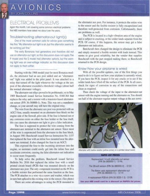
in tum butt-spliced to the existing wire to the sensor. (See photo)<br />
There are some advantages to using the PCB mounted to<br />
the alternator aux post. For instance, it protects the entire wire<br />
to the sensor and the fusible resistor is fully encapsulated and<br />
therefore well-protected from corrosion. Unfortunately, there<br />
are problems as well.<br />
The PCB is located in a high-vibration area of the engine<br />
and is subject to cracking. or the solder lands separate from the<br />
PCB. Of course, if this happens, the sensor may get a false<br />
alternator-out indication.<br />
Beechcraft then changed the design to eliminate the PCB<br />
and simply mounted a fusible resistor with leads instead. This<br />
seems to give good reliability, but the vendor that supplies<br />
Beechcraft with the part stopped making them; so Beechcraft<br />
returned to the PCB design.<br />
Know how your airplane is wired<br />
With all the possible updates, one of the first things you<br />
need to do is to figure out how your airplane is currently wired.<br />
If you have the PCB, inspect it for any cracks or to see if the<br />
solder lands have lifted off the surface of the PCB, In all cases,<br />
check for signs of corrosion in any of the connections and<br />
clean as required.<br />
Then check the voltage of the input to the alternator-out<br />
sensor with the engine running and the alternator on. You should<br />
see half of the alternator regular output voltage at the aux tenni-<br />
Alternator with fusible resistor (yellow arrow) on a printed circuit board.<br />
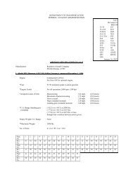
RAPID LIST PIICE$<br />
Replacement 14-volt alternator-out sensor<br />
(PIN 36-380000-1) - $196.<br />
The 28-volt version (PIN 36-380000-3) - $122.<br />
The Baron uses replacement alternator-out<br />
(PIN 36-380000-11) - $119.<br />
A replacement PCB kit (PIN 55-3025-1 S) - $108.<br />
Use your ABS credit card for a discount on RAPID's list prices.