RCT485 SMART LOGIC RELAY - Ring Automotive
RCT485 SMART LOGIC RELAY - Ring Automotive
RCT485 SMART LOGIC RELAY - Ring Automotive

You also want an ePaper? Increase the reach of your titles
YUMPU automatically turns print PDFs into web optimized ePapers that Google loves.
<strong>RCT485</strong> <strong>SMART</strong> <strong>LOGIC</strong> <strong>RELAY</strong><br />
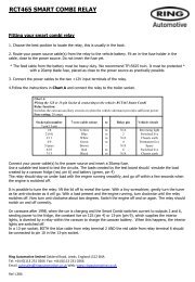
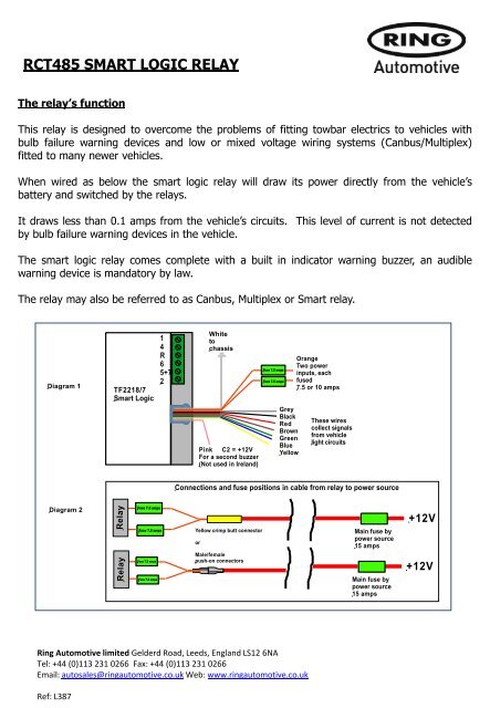
The relay’s function<br />
This relay is designed to overcome the problems of fitting towbar electrics to vehicles with<br />
bulb failure warning devices and low or mixed voltage wiring systems (Canbus/Multiplex)<br />
fitted to many newer vehicles.<br />
When wired as below the smart logic relay will draw its power directly from the vehicle’s<br />
battery and switched by the relays.<br />
It draws less than 0.1 amps from the vehicle’s circuits.<br />
by bulb failure warning devices in the vehicle.<br />
This level of current is not detected<br />
The smart logic relay comes complete with a built in indicator warning buzzer, an audible<br />
warning device is mandatory by law.<br />
The relay may also be referred to as Canbus, Multiplex or Smart relay.<br />
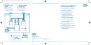
Diagram 1<br />
TF2218/7<br />
Smart Logic<br />
1<br />
4<br />
R<br />
6<br />
5+7<br />
2<br />
White<br />
to<br />
chassis<br />
Pink C2 = +12V<br />
For a second buzzer<br />
(Not used in Ireland)<br />
Fuse 7.5 amps<br />
Fuse 7.5 amps<br />
Grey<br />
Black<br />
Red<br />
Brown<br />
Green<br />
Blue<br />
Yellow<br />
Orange<br />
Two power<br />
inputs, each<br />
fused<br />
7.5 or 10 amps<br />
These wires<br />
collect signals<br />
from vehicle<br />
light circuits<br />
Connections and fuse positions in cable from relay to power source<br />
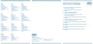
Diagram 2<br />
Relay Relay<br />
Fuse 7.5 amps<br />
Fuse 7.5 amps<br />
Fuse 7.5 amps<br />
Fuse 7.5 amps<br />
Yellow crimp butt connector<br />
or<br />
Male/female<br />
push-on connectors<br />
Main fuse by<br />
power source<br />
15 amps<br />
Main fuse by<br />
power source<br />
15 amps<br />
+12V<br />
+12V<br />
<strong>Ring</strong> <strong>Automotive</strong> limited Gelderd Road, Leeds, England LS12 6NA<br />
Tel: +44 (0)113 231 0266 Fax: +44 (0)113 231 0266<br />
Email: autosales@ringautomotive.co.uk Web: www.ringautomotive.co.uk<br />
Ref: L387
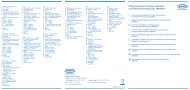
Fitting your smart logic relay<br />
1. Route your power source cable(s) from the boot to the power source and fit fuse holders<br />
in line in the cables, as shown in diagram 2. Do not insert a fuse yet<br />
2. Follow the instructions in Chart A and connect your 7-core cable, your relay and the<br />
appropriate wires in the vehicle loom.<br />
Chart A: Wiring the relay(s)<br />
Socket 7 core cable<br />
pin No. colour<br />
1<br />
2<br />
3<br />
4<br />
5<br />
6<br />
7<br />
12S Pin 1<br />
-<br />
Yellow<br />
Blue<br />
White<br />
Green<br />
Brown*<br />
Red<br />
Black*<br />
Aux Yellow<br />
-<br />
to<br />
Relay terminal<br />
number<br />
1<br />
2<br />
-<br />
4<br />
5+7*<br />
6<br />
5+7*<br />
R<br />
+12V (both)<br />
+12V (both)<br />
-<br />
SuperSplice<br />
number/wire<br />
colour<br />
1 - Yellow<br />
2 - Blue<br />
None - White<br />
4 - Green<br />
5 - Brown<br />
6 - Red<br />
7 - Black<br />
Grey wire<br />
-<br />
-<br />
Pink<br />
to<br />
Fuse 2 x 7.5amp<br />
Vehicle circuit<br />
LH flasher<br />
Fog lamp**<br />
Chassis earth<br />
RH flasher<br />
RH tail light *<br />
Brake lights**<br />
LH tail lights*<br />
Reverse<br />
Power +12V<br />
Power +12V<br />
Extra C2 switch (positive)<br />
* Connect thin signal wires black and brown to both the car’s side light circuits, black(LH)<br />
and brown (RH). Connect both black and brown of the 7-core to Terminal 5+7.<br />
** DUAL LAMP FUNCTION: If the stop/tail or fog/tail share a common wire, do not connect<br />
either of the sidelight signal wires (black or brown) from the relay, to the car. The relay will<br />
interpret the signal on the brake signal wire (red) or fog signal wire (blue) and operate the<br />
lights, including the side lights, correctly<br />
3. Connect the trailer reverse light wire to terminal R.<br />
4. Connect the grey wire to the car’s reverse circuit.<br />
5. Connect your power cable to the battery and connect a test board. Insert the fuses and<br />
test the installation by turning the car lights on and off and observing the lights on the test<br />
board.<br />
<strong>Ring</strong> <strong>Automotive</strong> limited Gelderd Road, Leeds, England LS12 6NA<br />
Tel: +44 (0)113 231 0266 Fax: +44 (0)113 231 0266<br />
Email: autosales@ringautomotive.co.uk Web: www.ringautomotive.co.uk<br />
Ref: L387