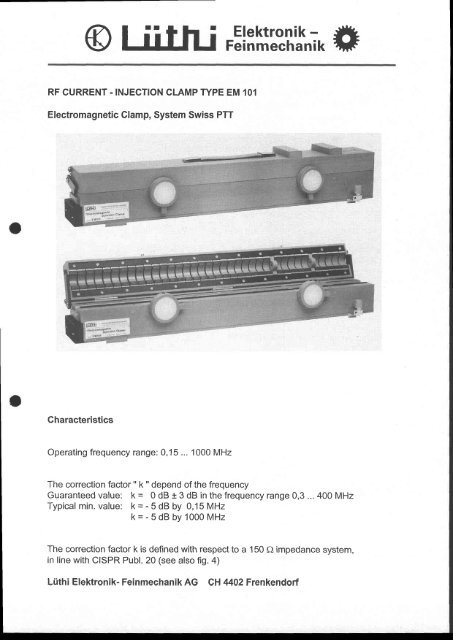
RF CURRENT.INJECTION CLAMP TYPE EM 101 Electromagnetic ...
RF CURRENT.INJECTION CLAMP TYPE EM 101 Electromagnetic ...
RF CURRENT.INJECTION CLAMP TYPE EM 101 Electromagnetic ...

Create successful ePaper yourself
Turn your PDF publications into a flip-book with our unique Google optimized e-Paper software.
<strong>RF</strong> <strong>CURRENT</strong>.<strong>INJECTION</strong> <strong>CLAMP</strong> <strong>TYPE</strong> <strong>EM</strong> <strong>101</strong><br />
<strong>Electromagnetic</strong> Glamp, System Swiss PTT<br />
Gharacteristics<br />
Operating frequency range: 0,15... 1000 MHz<br />
The correction factor " k " depend of the frequency<br />
Guaranteed value: ft = 0 dB t 3 dB in the frequency range 0,3 ... 400 MHz<br />
Typical min. value: k = - 5 dB by 0,15 MHz<br />
k=-5dBby1000MHz<br />
The correction factor k is defined with respect to a 150 fi impedance system,<br />
in line with CISPR Publ. 20 (see also fig. 4)<br />
Lüthi Elektronik- Feinmechanik AG CH 4402 Frenkendorf
with |,no:<br />
a)<br />
lr"tl<br />
Specifications:<br />
Dimensions:<br />
Diameter of the window:<br />
Weight:<br />
Verification:<br />
current induced by the <strong>EM</strong> clamp into a cable having 150 f, load<br />
at both ends. The clamp is hereby supplied from a 50 O- source<br />
having an electromotive force (e.m.f.) of the value Uo<br />
Nominal reference current from the same Uo<br />
e.m.f. into 300 O (2x 150O) total load I l,."r = ------<br />
300 f)<br />
<strong>RF</strong>-supply: <strong>RF</strong>-source of 50 O internal resistance<br />
Sine-wave operation, maximum allowed e.m.f.:<br />
0,15... 100 MHz : 14O V 'ms 100 W source ), max. 15 min.<br />
100... 230MHz: 140Vrms 100 W source ), max. 5 min.<br />
230 ... 1000 MHz: 100 V 'ms 50 W source ), max. 3 min.<br />
The severity of an immunity test with the above e.m.f. corresponds to an<br />
electromagnetic field-strength in the order of 100 V/m.<br />
b) Pulse mode operation:<br />
fast transients of 5ns / 50ns from a burst generator with a charging<br />
voltage up to 4 kV ( IEC Publ. 801 - 4 ).<br />
Directivity as current injection clamp: =10 dB beyond 25 MHz<br />
620 x 100 x 120 mm<br />
22 mm<br />
7,5 kg<br />
by Swiss Federal Office of Metrology CH - Bern<br />
Lüthi Elektronik- Feinmechanik AG CH 4/,02 Frenkendorf
<strong>EM</strong> K-factor<br />
in the frequency range 100 kHz to I GHz<br />
in a test setup according to IEG 61000-4-6<br />
Lüthi Elektronik-Feinmechanik AG<br />
CH 4402 Frenkendorf<br />
o<br />
tt<br />
o<br />
o<br />
t!<br />
l.L<br />
v<br />
4.0<br />
2.0<br />
0.0<br />
-2.0<br />
4.0<br />
-6.0<br />
Equipment used<br />
Network Analyzer Typ ZVR<br />
50 O to 150 O Adaptor<br />
50 A to 150 Q Adaptor<br />
0.1 1.0<br />
10,0<br />
MM Nr<br />
MM Nr<br />
MM Nr<br />
This is a computer created document and will not be signed.<br />
Frequency (MHz)<br />
4110<br />
4159<br />
41 60<br />
<strong>EM</strong> <strong>EM</strong> <strong>101</strong><br />
Serie Nr. SN 35854<br />
i I l\*<br />
llt<br />
-L<br />
Il f<br />
llt<br />
'I<br />
ltl<br />
100.0<br />
1000.0<br />
Date 28.06.2007<br />
Location METAS
o<br />
Bitte beachten:<br />
Zum Transport, bei Nichtgebrauch oder zur Lagerung<br />
soll die Zange nicht geschlossen bleiben.<br />
Die Verschlussknöpfe im Gegen-Uhzeigersinn in die<br />
obere Nute einfahren.<br />
Attention:<br />
Transport<br />
OFFEN / open<br />
For transport or not in use, do not close the clamp.<br />
The closing bottoms sef left in the sfop.<br />
schliessen / close<br />
Elektronik-<br />
Feinmechanik AG
1.<br />
Sunmary<br />
-2-<br />
Teehnical description of the EIrl clanpr type <strong>EM</strong> <strong>101</strong><br />
The electromagmetic (<strong>EM</strong>) clamp is an <strong>RF</strong> current lnjection clamp, having inductive<br />
and cqpacitive coupling and allowing the induction of large currents<br />
on cables in tlre frequency range of 0.15 to 1000 MHz.<br />
The El'l clanp has been developed by the Swl,ss PTT t ) r basically in order to<br />
test tbe innu4ity against induced currents on ttre cables of lnstallations<br />
containing i'nfornation technologry or teleconnrrnication eguipment. Ihis test<br />
is Üte nost i4portant elenentary <strong>RF</strong> imnunity test. Ttre Et'l cla.np shall be<br />
used whenever the coupling unitsr according to the CrspR Rrblication 20 [1],<br />
cannot be realized or applied (either due to tlre nunber of conductors in one<br />
cable or due to the slze of the instalratlen or for other reasons).<br />
With respect to tlre Lnjectlon of currents, üre Ell clamp has einilar prop_<br />
erties as the 150 ohn coupling unit. It nay be supplied fron an <strong>RF</strong> generator<br />
with 100 l{ or more Power in the frequency range 0.15 - 230 ttftlz or from a<br />
burst generator with a charging voltage up t'o 4 kv, allowing tests on special<br />
eguipment with high inunrurity level.<br />
Introduction<br />
l{henever an <strong>RF</strong>-electromagnetic field acts en a real installation (equipment<br />
with cables), the basic interference agentE arer to our experience, the<br />
common mode cufrents, induced on the cableg. These currents enter ln the<br />
apparatus at the connecting points of the qables and circulate through the<br />
chassis. This effect may be sinulated in an elenentary fumunity test by injecting,<br />
with Fn appropriate injection devicer comhoD mode currents on the<br />
cables.<br />
We note howevep that, existing injection devices, other than the <strong>EM</strong> clamp,<br />
are not convenient for infornation technology or telecomnunication eguipment<br />
because of the following reasonss<br />
- The construct.ion of the coupling writs I11 is not possible for cables<br />
having a large nunber of conductors.<br />
- The capacitiye IEC coupling clanp [IEC Publ. 801-4] has not<br />
coupling at €reguencies below 5 Mltz (fig. 7).<br />
- The absorbing MDS clanp and other current probes have poor<br />
when used as current injection devices (flg. 71.<br />
enough<br />
efficiency,<br />
The <strong>EM</strong> clamp has been developed in order to eliminate these drawbacks.<br />
r) $viss PTT, General Directorate, Research and Developnent, W 24,<br />
CH-3000 Berne 29.<br />
Ill CISPR rtblicat{on 20, 1985s ueaBurenent of t}re imnuyrity of sound and television<br />
broadcagt receivers and associated equipnent in üre freguency range<br />
1.5 MHz to 30 MHz by the current-injection rnethod.
2. Description of t}te <strong>EM</strong> clamP<br />
3.<br />
-3-<br />
The principle ef the construction is shown in the fig. 2 and 3.<br />
The EI'l clarnp i4duces a current on a cable by using incluctive and capacitive<br />
coupling at üre same tine; the desigmation "<strong>EM</strong>x (electronagnetic) comes frorn<br />
this feature. the fig. 2 illustrates the inductive coupling: An <strong>RF</strong> transforner<br />
having q one turn primary circuit uses the clanprs ferrite tube of<br />
60 sn length aq rnagnetic core. The fig. 3 represents the capacitive coupling<br />
between ttre cable rurder test and üre prinary turn (seni cylinder of, a metal<br />
foil in üte grroove of üte clanp).<br />
The resistance R2 in the inpedance 22 enhances the directional effect and<br />
dirninishes the influence of the load at the "back sLde" of the clarnp.<br />
Thanks to üre prrecise mechanical constructlon of üre clamps (tight electrical<br />
toleranees) it was possible to suppress the geries impedance 21 in<br />
the nodel El'l 1Q1. It was also trrossible to tmprove the frequency range up<br />
to 1000 MHzr by nodifying the prinary winding.<br />
Calibration<br />
The Et! clamp is provided to replace a'1150 ghm coupling unit", therefore<br />
such a unit is used as calibration reference.<br />
The calibratio4 procedure is lllustrated in the fLg. 4. Tbe fig. 4a shows<br />
the reference eet upr containing two resistive 150 Ohn coupling units, connected<br />
together and being used as transmitter and load units resPectively.<br />
In the second calibration step the transnitter r:nit is replaced by the <strong>EM</strong><br />
clamp according to fig. 4b.<br />
A correction factor 'k' in function of the frequency shall be determined,<br />
being defined as:<br />
k (dB) = reading h'ith clanP<br />
(Ievel "4b" in ds(ttv))<br />
reference reading<br />
(level '4a' in dB(Pv))<br />
The typical correction factor for a clamp EI't <strong>101</strong> is given in tlre fig. 5 for<br />
the freguency range 0.1 to 1000 MHz.<br />
The induced current "Iind" by the <strong>EM</strong> clanp Ln a cable with a 150 0 terminat<br />
j.on at both e4ds Inay be calculated as followe:<br />
rind<br />
a.B( PA)<br />
rref<br />
dB( pA)<br />
+k<br />
Reference current from fig. 4a: Iref =<br />
rref<br />
as( lrA)<br />
uo<br />
d8<br />
uo - 50 dlB<br />
dB( pv)<br />
uo<br />
300 Q<br />
eletronotive force (e.m.f.! of the <strong>RF</strong> generator
4. D
-5-<br />
In pulse rcde operatLonr laet tranelentg of 5 ng./50 ns IIEC Publ. B0l-41 fron<br />
a burst generator wlth a charging rroltage up to 4 kV nay be applied: no saturation<br />
ie observed and tlre pulac eha;re is b€tter reproduced than wl,th tlre capacitive<br />
IEC couBling clanp (fig. 6). ltrus the <strong>EM</strong> clamp may favourably replace<br />
the IEC capacltive clanpl further on, the <strong>EM</strong> clanp ie less bulky than üre capacitive<br />
c1a.np.<br />
7. Use of the El clq$p for l.Enu+lgy 'ggg,]!s<br />
Swiss gtT)<br />
To equlpnent with snall or nedir:m d,fuocnel,ona (nax - 0.8 n size), the current<br />
lnJection nethod FÄy be aBplled ln tlrs frequency range of 0.15 ... 230 Wz<br />
uith a sirtllar D€asurenent iet-up ae d.scrlb.d ln tlt€ CISPR hrbllcatlon 20<br />
[ lJ . On cables wlth nultlple conductora, ths E{ clanp shall be apptled Lnstead<br />
of a coupling unlt.<br />
The g1g. 8 givee an exa.nple of such a Deagurenent 8ct-up. In order to define<br />
the load at the rear side of thE claarp, a capacltl,ve coupling has been realized<br />
betueen cable and ground plane ( 10 n of cablc wound up on a netal plate<br />
placed on the grround plane) .<br />
Note3 The better definition of load J.mpedance on the rear side is recomrnen-<br />
A;ä; because an aurciliary egulpnenü, connected dlrcctly to üre rear side of<br />
the E!,1 clamp, will be less effectlvely decoupled than an auxillary equipment<br />
that ls connected tlrrough a coupling unit. In üre callbratlon set-up (ftg. 4b)<br />
the current, injected to the rear side, ls . 10 dB lower at frequencies beyond<br />
25 tttrlz ütan the current on the front elde. For lower frequenciesr the currents<br />
on üre front and pear side have nearly the gasre nagmitude.<br />
In large installat,ions (groups of racks with t dense network of cables), the<br />
<strong>EM</strong> cla.rp shall be placed, successively, on each of üre representative cables<br />
of the specific system racks (type tests).
Fio.2: Circuit 6quivalent slmplifid du<br />
Simplified equivalent circuit of<br />
Fio.3: Circuit €quivalent slmpllfiÖ du<br />
Simplilied equivalent clrcuit of<br />
21-22<br />
z3<br />
z4<br />
.tLt<br />
JL2<br />
JC<br />
G<br />
z1-z?<br />
z3<br />
z4<br />
atLl<br />
JLz<br />
JC<br />
G<br />
z1<br />
--<br />
tL2<br />
lli}ätati?{r.f4.aEii'#-En, 1l5:Y-i&QÄll<br />
l Inp6ilancct cn r6rlc dane Ia rplrc prlnatrc<br />
: Iep€drnec dc lrSgulpaErnt aour t.at<br />
r l4*dancc du elblc I l.rrrllro de la plncc<br />
r Courant lnductlt prlnatrc<br />
r Courant laaluctll tccoadalre<br />
r Co\rrant capacltlt<br />
: G€n€ratcug du ttEnal EF<br />
r Sertes Lapedlancer ln ütc prlnäry turn<br />
: Iopedance of üre El,t:I<br />
r lopcdcncc of thr cablc on üre rcar elde<br />
l Induqt,tvt prtoary c.urrGnt<br />
l Indue't,lvc recondary errrant<br />
I Capacltlve eurrcnt<br />
r <strong>RF</strong> algmal generrtor<br />
couplage Inductif<br />
the inductlve coupling<br />
couplage capacltlf<br />
the capacltive coupling<br />
of tlrr<br />
clarlp<br />
I<br />
rLl i I<br />
I<br />
L2,R2<br />
I<br />
EST<br />
EUT<br />
L1, C1,R1<br />
z1 facultaclf<br />
Zl optlonal<br />
1-7: |l\r.be de ferrltee longrueur 60 o<br />
2 : Derol-cylindre cn t61e de quivre<br />
Lca €l6aent8 LaPortantg de<br />
chague clrcult 6ont repr6sentEe<br />
en lralto forgs.<br />
1-7r Fcrrlto tube, total lengrth: 60 o<br />
2 r Seni cyllnder of copper loll<br />
f?|e &portant elcaante of erch<br />
clrcult arc drava ln heavy llneo.
o<br />
ol<br />
cc<br />
o.<br />
g^<br />
oR<br />
o9<br />
cD'=<br />
G'=<br />
o.<br />
30)<br />
oc<br />
(t= CL<br />
O=<br />
E'O<br />
oo<br />
otr<br />
öo<br />
orff<br />
fg g;<br />
g; sZ<br />
'auJ E't<br />
-se * g<br />
96 .98<br />
UJO OCC<br />
..t<br />
..r (El<br />
€.1 q.l<br />
ol ol<br />
iil äl<br />
o lF<br />
o=<br />
|JC<br />
L-<br />
?L<br />
;o<br />
=4.<br />
qe<br />
E(,<br />
rlf E<br />
er9<br />
'ög<br />
@F<br />
=<br />
tr,q oI)<br />
er l-<br />
FL<br />
c<br />
o o<br />
o<br />
.:<br />
TL<br />
q<br />
I<br />
a<br />
rll ar A<br />
FF Q,d<br />
-b Entr<br />
Gto<br />
+J '{<br />
tr+)<br />
oq<br />
EO<br />
=9<br />
itE<br />
69<br />
rs<br />
rQ l!<br />
(DE<br />
ctcl<br />
oo<br />
rn u)<br />
trltrl<br />
EO<br />
=<br />
UJ<br />
o9 (JE<br />
tro<br />
cL(,<br />
P P SE<br />
o<br />
t{<br />
tlr<br />
0ro<br />
4J rt<br />
|!,U<br />
trtr<br />
roo<br />
+J 4J<br />
4J .lJ<br />
F<br />
o<br />
= tlt<br />
=<br />
tlJ<br />
o3<br />
Otr<br />
C(E<br />
o-o<br />
(o=<br />
-ul<br />
o<br />
lro<br />
CoF<br />
.=o<br />
()<br />
eä<br />
oc)<br />
org<br />
Q)e<br />
Eö<br />
r-=<br />
:t c)<br />
o',o,<br />
3ä<br />
TL (J<br />
..t<br />
1r)1<br />
.l<br />
ol<br />
EI gto$NoNtüto@<br />
l(<br />
'''l<br />
,.t. '<br />
'...l-"'I<br />
....r'-.1<br />
-T-l<br />
...1-...1<br />
' t""1<br />
i<br />
o<br />
o<br />
o r<br />
o.<br />
o<br />
N<br />
r<br />
E
ffi4<br />
/vlI<br />
r- 36<br />
t_ r- o<br />
,.r,/<br />
tt'l It<br />
20 ns<br />
lr<br />
\^r<br />
-9-<br />
. rl. tttl<br />
/\l'<br />
/rt"J It<br />
a.,,1{l \<br />
!r'<br />
60ns \A<br />
'\<br />
\,*<br />
I I<br />
Pince <strong>EM</strong><br />
<strong>EM</strong> clamp<br />
R6fdrence: Boite de couplage<br />
Reference: 150O coupling unil<br />
I I<br />
Fig.6 lnjection d'impulsions brÖves 5ns/50ns (salve) avec<br />
la- pince <strong>EM</strong> et la pince capacitive CEl.<br />
Iniection'of fast transients 5ns/501!^(burst)-withthe<br />
FM clamp and the capacltlve IEC coupllng clamp'<br />
ltontege selon fLg. 4bl Tenslon rnesur€e sur Ia<br />
charge A (150 0).<br />
- R6f6rence: Botte 150 g' flg. 4a.<br />
- Tension de charge du gr6n€rateur de salves: 1 kV<br />
Test set-up accorÄlng co f19. 4b: Voltage neasuled<br />
across ttre load A ( 150 Q) .<br />
- Reference: 150 0 couplJ.ng unlt, fLg. 4a.<br />
- ChargLng voltage of tlre fast transient generator: 1 kV<br />
I<br />
Pince capacitive CEI<br />
Capacitive IEC coupling clamP<br />
I
oo<br />
ALI<br />
o,<br />
-{E<br />
h0,<br />
tüu<br />
>o t{<br />
grq<br />
o o<br />
OE<br />
l.t +J<br />
o<br />
rro<br />
UrJ<br />
6<br />
IH UT<br />
c<br />
c.A<br />
o t1d<br />
..{ l.l<br />
+,o<br />
oo<br />
OU<br />
l{ct<br />
11<br />
o€<br />
oo E<br />
oul<br />
I '.1<br />
+J .{<br />
,o<br />
t! |tt<br />
O+J<br />
u<br />
co<br />
Orf<br />
Ot<br />
.A IJ'<br />
!ocn<br />
d o.'{<br />
q'.1 lrr<br />
e><br />
O olu<br />
UTJ O<br />
'l<br />
I<br />
.l<br />
t'|l<br />
'.{ |<br />
,ul<br />
r(|<br />
a<br />
Lt.<br />
otn<br />
>_{<br />
','t ll.t<br />
|!<br />
g.{<br />
E<br />
q,<br />
CE<br />
..1 o<br />
rC,<br />
DTJ<br />
u rG,<br />
OU<br />
t{O<br />
trl{<br />
Og{<br />
O<br />
o<br />
q, F{<br />
E<br />
c<br />
(/l0<br />
l.r r-{<br />
)a)<br />
osl<br />
1)<br />
uul<br />
tü '{<br />
tlJ F{<br />
A<br />
o|!<br />
o4J<br />
tt ro<br />
cn<br />
O llf<br />
u .?l<br />
.,{ +,<br />
fit -{<br />
}{ul<br />
rÜo<br />
O{q<br />
eo<br />
O-{<br />
utt<br />
aa<br />
rl<br />
;l<br />
;_' I<br />
c]oocl(]oc]<br />
ataalta<br />
Loc]noLnon<br />
l-rNCVtlll<br />
co<br />
-d<br />
.Y<br />
'lrtl<br />
. PIlJ<br />
Ina oa = trll N<br />
OOO<br />
i tt'<br />
es<br />
|!k<br />
a^<br />
O*<br />
(, O{<br />
a)E<br />
Erü r{<br />
OU<br />
k<br />
;3 tl<br />
s 8,li<br />
o oT:<br />
o H+<br />
E Lt r:<br />
r{ t 1'l<br />
AU.I<br />
I<br />
il<br />
ata<br />
cltno<br />
cn cn .f<br />
lll<br />
(J<br />
+J<br />
c<br />
C'<br />
l.O<br />
ao<br />
8'i<br />
OE<br />
tt<br />
c<br />
f{O<br />
, ."'l<br />
(l)r,<br />
4J ('<br />
oo<br />
.ng o.n<br />
C'{<br />
+J<br />
= 56 H<br />
1-' c 1,.<br />
o.9B<br />
=<br />
cl<br />
l(<br />
cl<br />
O<br />
16(ll<br />
o.!<br />
.Ä<br />
t4 E<br />
..{ o<br />
+JUl<br />
,a<br />
fl
o<br />
t)<br />
c,<br />
e<br />
c<br />
o<br />
4J<br />
u<br />
o<br />
tr<br />
.Ft<br />
I<br />
+,<br />
C<br />
o<br />
H<br />
!<br />
a t)<br />
o<br />
+J<br />
k<br />
o<br />
tt{<br />
O{<br />
, I<br />
IJ<br />
C.'<br />
q<br />
fc<br />
c,<br />
o<br />
o<br />
fr<br />
A<br />
:l<br />
.,{ u'l<br />
|<br />
&rl<br />
aG)<br />
E1)<br />
rd<br />
sl r{ C{<br />
o<br />
+JU<br />
T6<br />
C'<br />
qe<br />
,O t!<br />
(t<br />
uc o<br />
o<br />
g.r o<br />
oa<br />
xo<br />
E:I<br />
u<br />
tr<br />
(6A 4J<br />
c Oco<br />
=E<br />
5(J<br />
5F<br />
x<br />
a tr<br />
a<br />
o<br />
{Jl<br />
o<br />
.p<br />
ö<br />
C<br />
lJe<br />
urx<br />
co<br />
q, r0<br />
..{<br />
F{<br />
&<br />
F{<br />
o o<br />
U<br />
ETJ .!<br />
OFI<br />
FCa<br />
r! (,<br />
o ..{<br />
F{<br />
C, F{<br />
F{ lü<br />
!+J<br />
rio<br />
UE<br />
q,<br />
..{<br />
fJ<br />
..{<br />
u|!A{<br />
r! C,<br />
0<br />
t<br />
I<br />
I<br />
+<br />
E<br />
ü<br />
{i<br />
U<br />
>4J<br />
ktr<br />
|lto<br />
.dg<br />
r{ C{<br />
.A ..1<br />
XJ<br />
,V<br />
@ffiiF:fifll?f,hlu#<br />
L2<br />
CORRELATION between the fieldrs method and the current iniectionrs<br />
method effect ( eU <strong>101</strong> or<br />
COtt) on the EUT<br />
The.tleyeloppers (lrlr" Bersier and Ryser, General Directorate<br />
Swiss PTT ) of the El{ C1amp have given us the following<br />
explanation:<br />
see fig.8 (proposed set-up fpr the current-injection<br />
method)<br />
I Volt (source voltagp) at output Tt<br />
corresponds to a field strength of about I v/meter<br />
The correction values given in the measured curve<br />
enclqsed with the <strong>EM</strong> <strong>101</strong> are to be taken in account<br />
as follows:<br />
In the case of negative values the source voltage<br />
is tq be incrased by the values as Per the curve;<br />
when positj-ve, it is to be decreased accordingly"<br />
Injection with a CDN (Coupling-d,ecoupling Network)<br />
requires no correction.
Proclicql cpplicotion of the <strong>EM</strong> clomp:<br />
SC 65AIWG4 (CH-Bersier, Szenlkuti)2<br />
CISPR/AAVGI (Bersier)l I<br />
CISPR/GAVG3 (Bersier, Ryser)6<br />
Morch I 991<br />
New test setup yielding better reproducibility of the lesls qnd better<br />
decoupling of -the ouxilioqT equipmenl<br />
Investiootions performed ot the Swiss PTT show lhol o ferrile.lube of high. perme,obilit"y,<br />
phceddireclly ol lhe reor side of lhe. <strong>EM</strong> clomp.,.imProves lhe rep^roducibility ol the<br />
immunity tests'qnd efficiently decouples lhe ouxiliory equipmenl (AE). This selup is<br />
shown ih ligures I ond I o.<br />
With the setup of fis. I the influence of the reor c.ircuit (AE.impedonce,, lengrh ond lqrout<br />
of the codlef on-the iniectio.n to the EUT'side does usuolly nol q199de + J dB, wilh<br />
äiept .rä<br />
i[r yätl,ät &ri;ö Alibrorion, ,in rhe frequencv ,[p-nge.l:Mfl+"409-ll4Ez<br />
tseä fiq. 3 ond 41. Conseqirently in this fiequency ronge-llg<br />
üsed för ony typd of AE ond cobling.<br />
lr, tt. ftrouency ronge 150 kHz...l MHz the slrongest inlluence from lhe reor circuil is<br />
ätää:;ü;;;;i[.'.obl. ii-riorr änd rhe comäon mode impedonce of the AE is<br />
hü[:'ihil i;'iü'rilr.tiär *trln irre Ae inpuicircuits ore insuloted'from the AE'eorth.<br />
For the lesls in lhe frequency ronge 150 kHz...l MHz the reproducibiliry moy be im'<br />
proved through the following meosures:<br />
. Connecl o 150 o resistor between the ground poln! of the AE inpul'circuils (generol'<br />
ly lhe ground pin of the inpul conneclor) ond the GR'P'<br />
- lf this is not feosible lhon increose lhe copocilonce between lhq coble. ond the GRP<br />
är'iüä ä;:ii;-J nä irl..ril tyriem,-äi much os possibl" (!0 m coble ploced in<br />
iis:;;i; it'äOnp or cbpocitivä winding on o metbllic plole).<br />
Fio. 5o shows lhe decoupting obtoined for the AE yqing lhe setup of fig.'.1 in lhe cose<br />
Li"o itoä'ääülä.itii-JiJdl,üli'ö ili b;-i';äiru-uv-'sing. o läns co-ble ond, if ne<br />
cessory, on odditionol lerrite tube, direclly ol lhe AE [tag. Jbl'<br />
T0207001
{r,<br />
S u<br />
r-<br />
()<br />
I<br />
L d<br />
q)<br />
E<br />
s<br />
q.t<br />
1^<br />
>)<br />
v,<br />
s o<br />
(J<br />
o,<br />
s,<br />
l-f<br />
E<br />
u<br />
o<br />
Itl<br />
YT<br />
1€l<br />
q)4<br />
-t-r 5<br />
. i.r-l<br />
L<br />
a<br />
^<br />
s<br />
d<br />
() I<br />
E<br />
ut<br />
=.<br />
o!rr<br />
2<br />
I ItIttl<br />
I<br />
sE$s p<br />
c,<br />
h<br />
E<br />
'5<br />
3-r<br />
€o<br />
H+<br />
I<br />
\)<br />
-o<br />
ü-i-:5<br />
St<br />
s<br />
T o<br />
.g<br />
oJ<br />
roE<br />
eE<br />
ö<br />
:r۟ I<br />
.=lbä -g<br />
u-|u- O- F
a<br />
:<br />
o<br />
F<br />
z a()<br />
-3<br />
rl<br />
a :<br />
L<br />
c,<br />
l,<br />
t<br />
L<br />
{<br />
I<br />
I I<br />
I<br />
I<br />
I<br />
l'<br />
I<br />
il<br />
tt<br />
-)-<br />
q-<br />
E<br />
s rJ<br />
t,<br />
E UJ<br />
A.<br />
e,<br />
\5<br />
ql<br />
-x S<br />
Sl<br />
E<br />
'.t<br />
's<br />
:!o<br />
s (+-<br />
H<br />
E<br />
x<br />
E<br />
sl<br />
og.<br />
\t<br />
t{<br />
r:it<br />
sic<br />
vl<br />
: )<br />
.g<br />
oo-<br />
=t<br />
o co<br />
o-<br />
! cf<br />
o<br />
o)<br />
o<br />
; o,nc<br />
.9 ouo<br />
.=cD<br />
.tl<br />
o<br />
o<br />
_g o-<br />
E<br />
o x<br />
|r,<br />
öl<br />
-l<br />
öt<br />
1!l
o<br />
-4<br />
Fig. 2: Colibrotion of the inieclion svsfem<br />
of Referen.. ,.r - up wilh two | 50 O .orpling ,nits<br />
Umr @) Load A Tronsnitter<br />
unil<br />
i-it6?f if Ocm j--1egt-,, ^<br />
bl The lronsmiHer unil is reploced by lhe <strong>EM</strong>. clomp<br />
Correclion loctor q[ the <strong>EM</strong> - clomp:<br />
| = U-(bl -U-(ol<br />
dB dBlpvf dB(Pvl<br />
ur, (b) r<br />
kc, t= U-(cl - U-(ol<br />
dB dBtrrv) dB(PV|<br />
U^r(c) Load A<br />
for the some e.m.[. of G<br />
The lronsmitter unil is reploced by the inleclion system I<strong>EM</strong>'clomp + ferrile tube]<br />
Correclion locJor of the inieclion syslem:<br />
CO<br />
!<br />
.).,<br />
5.0<br />
0.0<br />
-5. 0<br />
-10.0<br />
-15.0<br />
<strong>EM</strong> - clan<br />
lor the some e.m.f. of G<br />
El4 - clam<br />
k - correclion loctor for the clomp <strong>EM</strong> l0l<br />
k cr = corrädion fodor for the iniection system <strong>EM</strong> l0l + lerrite tube
Fiq. 3 + 4: fnfluence of the AE - imoedonce ond cobfe foyoul on lhe iniecled levef<br />
lo the EUT.<br />
EUT simuloted by typicol impedonce 150 O.<br />
|nieclionsyslem:<strong>EM</strong>.c|omp+[erritelube..]l'...--_..<br />
EUT<br />
i,gl<br />
Fig.3:<br />
70. o<br />
3S 65. 0<br />
o -13 60. o<br />
F =<br />
=t 55.0<br />
En - clam<br />
..4..4//ta a<br />
Fcrritc tqbc<br />
DTs (so ru;<br />
50. 0<br />
100tr i 11 10M<br />
Fiq. 4: Totol coble - lenglh: 2,4 m (- 0,8 m on lhe GRPI<br />
s<br />
..3<br />
et<br />
F =ru<br />
70. o<br />
65. O<br />
60. 0<br />
55. O<br />
50. 0<br />
45. O<br />
en - clam<br />
Fcrritc tube<br />
DTs (so n')<br />
Residual cobte -<br />
hnath plu,ccl on<br />
ttre" cCR( ft zig-zag)<br />
:-r-rflrlr<br />
Re(erence<br />
set - up<br />
Totol coble - length: 12 n l- 10,4 m in zig - zog on lhe GRP)<br />
+t-<br />
-e-+<br />
+r-rl-<br />
1001'l<br />
rr U ElrT by tlrc rcfcrencc lat-uP (U1"1)<br />
AE<br />
i':r?P;L<br />
br U gg1 shcn AE l! tcflilnlt'd vlth 150 O<br />
at U EIJT whrn lü ll in oPcn clrcrrlt<br />
dr U OjT vhcn L.E lt ln short' clrdJit
Fig. 5: Prolecli?n o[ the ouxiliory equiPmenl iAEl<br />
Inieclion syslem: <strong>EM</strong>'clomp + ferrite lube<br />
EUT= l50O;AE= l50O<br />
o) Tolol coble length: 1,8 m<br />
,uEuf<br />
t:l<br />
Protection of the AE - U^: - Urt<br />
dB dB(pvf dB(Pvl<br />
Et'l - clam<br />
-6<br />
Fcrrita fqlre<br />
DTs (so ru;<br />
b) Tolol coble length: 12 n l-9,7 m in zig - zog on lhe GRPI<br />
f<br />
w<br />
5<br />
5<br />
lrJl<br />
Ueur en - clam<br />
10. 0<br />
dB 0.0<br />
-10.0<br />
-20. 0<br />
-30. 0<br />
-40. o<br />
-50. 0<br />
Fcrrita tube<br />
DTs (so rt';<br />
Urc<br />
l:1<br />
Cable 9,7nt<br />
in ziq.7üq or1<br />
the ciep -<br />
Ferrite tube<br />
Lro r 3cll
CEf 10004-6<br />
I May,199S<br />
/ tECsol-6<br />
Reference level and required HF power of the power amplifier pA<br />
In the frequency rangs 0.1S ... 230 MHz<br />
The prescribed<br />
vollage test levels are shown in item S, table 1.<br />
This is lhe not diregt measurable <strong>EM</strong>F at the exit of T2.<br />
Tabls I Tosl lovols<br />
Frequency range .15 MHz - 80 MHz<br />
Level<br />
I<br />
2<br />
3<br />
Xtt<br />
Voltago lovol(o.m.l,)<br />
U. [dBuVl U. M<br />
120 I<br />
130 3<br />
140 10<br />
spocial<br />
For HF_cunent injection either a CDN or a Current Injection Clamp (<strong>EM</strong> <strong>101</strong> or Current<br />
Clamp 5:1) can be used, depending on the number ol leads.<br />
The decouplin$ against the AE is contained in both the CDN and the <strong>EM</strong> <strong>101</strong>. In order to<br />
g!!{n_e well reproflucible result below 20 MHz, it is advisable to use an additional decoupling<br />
(FTG Glamp). In this connection please note tliat the Current Clamp 5:1 without decoupling<br />
does not produce reproducible results.<br />
The.required outpqt power of the PA for testing at levpl 3 (10 V.,.,.) and B0 % amplitude<br />
modulation depth is shown in table D.1.<br />
The evalleble oupul poner ol the power ampllller PA, llgure 3 can be determlned by taklng<br />
lnto accounlfhe allenuator T, (6 dBl, the amplltude modulqllon deplh (80 %), see llgute 4 and<br />
the minlmum coupling laclor ol lhe used CDN or clamp.<br />
Table D.l Requlred pourel ünplltior oulput powet to obtaln a lest levol ol l0 V.-..<br />
lplectlon devlce Mlnlmum coupllng faclor<br />
* r.6 [dBl<br />
Requked power at<br />
outpul of PA lWattl<br />
CDN 0 7<br />
Gunenl clamp<br />
wlnding raüo 5:l<br />
.14 176<br />
<strong>EM</strong>-clamp .6 28<br />
Determinatlon of [he power required for measuring by means of the <strong>EM</strong> <strong>101</strong>:<br />
At 150 Hz k equalq -5 dB; the ratio is 3.16 (see table in annex 2)<br />
Ppr=3.16'7=22W.<br />
lf the FTC <strong>101</strong> is used as an additional decoupling in order to guarantee reproducibility below<br />
20 MH4 more power is required in the hatched frequency range. At the most unfavourable<br />
frequency of 1.5 MHz k equals -12 dB: the ratio is 15.85<br />
Ppe=15.85'7=111W.<br />
lf the range betwepn 1 and 1.5 MHz is not r€levant, g0 W are sufficient. etc.<br />
Annex 1<br />
2<br />
coupling factor of <strong>EM</strong> <strong>101</strong> + FTC <strong>101</strong><br />
table dB / Watt<br />
3 measuring of the reference<br />
4<br />
5<br />
substitute circuit diagram with CDN<br />
substitute circuit diagram with <strong>EM</strong> <strong>101</strong><br />
Lüthi Elektronik-reinmechanik<br />
CH-4402 Frenkendorf
o<br />
Verlflcatlon of the system <strong>EM</strong>l0l + FTCIO|<br />
ln the frequency range 150 kHz - 1000 MHz<br />
with reference to a 150O source I load system<br />
<strong>EM</strong><strong>101</strong> Ser. Nr.: 35555<br />
FfC <strong>101</strong> Ser. Nr.: 4631<br />
00<br />
g0<br />
4<br />
z<br />
lt-z<br />
f4<br />
J<br />
-6<br />
-8<br />
4<br />
2<br />
0<br />
0O -Z<br />
.lt<br />
;4<br />
E-5<br />
s<br />
-':<br />
'8<br />
-10<br />
-12<br />
-14<br />
Swisscom CT-EEC Ry<br />
Date 07.04.1999<br />
Made by: Lüthi Elektronik-Feinmechanik AG<br />
CH 440zFrenkendorf<br />
<strong>EM</strong><strong>101</strong> (without FTC)<br />
10<br />
Frequency<br />
IMHzl<br />
System <strong>EM</strong><strong>101</strong> + FtC <strong>101</strong><br />
10<br />
Frequency<br />
[MHzl
Prüfleistung des PA<br />
Output power of the PA<br />
dB:= I ,2..23 Pl := I<br />
tpi \<br />
dg := lo.tog{;; }o<br />
\r r /<br />
23<br />
22<br />
2l<br />
20<br />
t9<br />
l8<br />
t7<br />
l6<br />
l5<br />
t4<br />
l3<br />
dB tz<br />
lt<br />
t0<br />
9<br />
E<br />
7<br />
6<br />
5<br />
4<br />
3<br />
2<br />
I<br />
100 t20<br />
P2(dB) '= rol).nr<br />
"*p(*.as.r4<br />
2<br />
P2(dB)<br />
1.259<br />
t.)ö)<br />
r.yrJ<br />
a.Jtz<br />
5.toz<br />
J.vö l<br />
5.Ut2<br />
o.J I<br />
L>.+J<br />
IU<br />
| /,,)ö><br />
| 5.ö49<br />
tt.y)J<br />
2).1r><br />
l.ozJ<br />
39.Ur<br />
50.t l9<br />
63.096<br />
79.43J<br />
IUU<br />
I z),öv)<br />
I )ö.4öv<br />
199.526
o<br />
!ts,<br />
E<br />
q)<br />
E<br />
€,<br />
L<br />
=<br />
a<br />
(tr<br />
ct<br />
E<br />
(1,<br />
(J<br />
F -<br />
(l'<br />
L<br />
(l,<br />
rts (t,<br />
E<br />
ct)<br />
F<br />
-<br />
rl|<br />
J<br />
o 3t,<br />
(,<br />
E N<br />
g<br />
(l)<br />
L<br />
(1,<br />
rts q,<br />
E<br />
.=<br />
\1,<br />
L--<br />
.{-,<br />
c<br />
o<br />
_o)<br />
J-<br />
_N =<br />
EE<br />
cc<br />
.(').9<br />
U) U)<br />
r-O<br />
(t)E<br />
=o-<br />
()E<br />
(|)o<br />
Mo<br />
oz.o=<br />
C) I.U<br />
b<br />
-t=<br />
:$<br />
{ra<br />
_öE<br />
)oa=<br />
co<br />
T'<br />
(o t<br />
oo<br />
oo<br />
E,E<br />
oc)<br />
(l)<br />
U'<br />
a<br />
(Dr-<br />
-l-<br />
9ö<br />
E9<br />
59 -o<br />
=(l)<br />
E:o<br />
o_F<br />
Eö<br />
l-<br />
H#t<br />
cc<br />
oo<br />
s-<br />
:
z,<br />
Gt s)<br />
- -<br />
E'6<br />
JJ<br />
II<br />
E€)<br />
N(J<br />
cg<br />
(l)o)<br />
LL<br />
(l)c)<br />
||r rF<br />
€) G'<br />
ü,ü,<br />
o<br />
lg<br />
U)<br />
I<br />
ul<br />
o<br />
o<br />
E<br />
= o<br />
o<br />
&<br />
I Oo<br />
t<br />
O<br />
E<br />
o<br />
o<br />
9b<br />
JJä<br />
s€<br />
=<<br />
o)<br />
o<br />
-v E<br />
I.TJ<br />
+t+ty<br />
o_F
s<br />
o<br />
ITF<br />
O5<br />
1r-<br />
- lll<br />
älrJ'=<br />
Es)<br />
- I<br />
E'6<br />
g<br />
+(J<br />
- Fe'u-C9ri(!E'<br />
6m<br />
N rr<br />
{J<br />
rE=<br />
ler g<br />
s€, o<br />
lrJ r -!r<br />
;<br />
s<br />
=(tr<br />
L:a<br />
Y!(l,<br />
vtF<br />
G,=<br />
O Eru<br />
NC)<br />
CG<br />
(l)c,<br />
LL<br />
ee<br />
(, q,<br />
ü,8<br />
(l)<br />
i9<br />
a I<br />
uJ<br />
o<br />
o<br />
o<br />
E<br />
= o<br />
o<br />
P<br />
E,<br />
()<br />
o<br />
3<br />
E.<br />
()<br />
I.JJ<br />
o<br />
c)<br />
FLL<br />
E<br />
o o<br />
!b<br />
JJä<br />
3€<br />
=<<br />
I<br />
=*<br />
===<br />
ooo<br />
= gt -cDO<br />
-v.<br />
=(U<br />
o_F