XR30CX
XR30CX
XR30CX

Create successful ePaper yourself
Turn your PDF publications into a flip-book with our unique Google optimized e-Paper software.
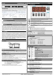
dIXEL Installing and Operating Instructions 1592020030<br />
Digital controller with off cycle defrost and AUX relay<br />
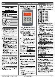
<strong>XR30CX</strong><br />
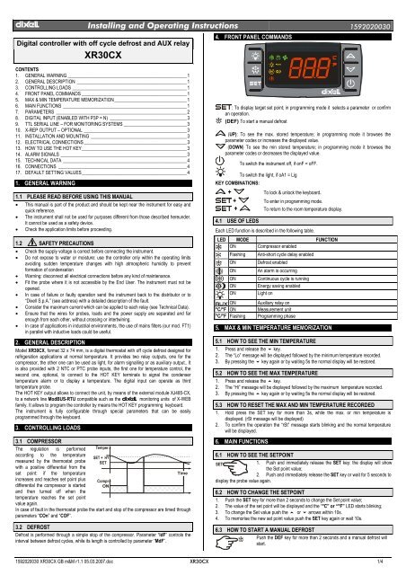
4. FRONT PANEL COMMANDS<br />
CONTENTS<br />
1. GENERAL WARNING ___________________________________________________1<br />
2. GENERAL DESCRIPTION _______________________________________________1<br />
3. CONTROLLING LOADS _________________________________________________1<br />
4. FRONT PANEL COMMANDS _____________________________________________1<br />
5. MAX & MIN TEMPERATURE MEMORIZATION_______________________________1<br />
6. MAIN FUNCTIONS _____________________________________________________1<br />
7. PARAMETERS ________________________________________________________2<br />
8. DIGITAL INPUT (ENABLED WITH P3P = N) _________________________________3<br />
9. TTL SERIAL LINE – FOR MONITORING SYSTEMS ___________________________3<br />
10. X-REP OUTPUT – OPTIONAL ____________________________________________3<br />
11. INSTALLATION AND MOUNTING _________________________________________3<br />
12. ELECTRICAL CONNECTIONS ____________________________________________3<br />
13. HOW TO USE THE HOT KEY_____________________________________________3<br />
14. ALARM SIGNALS ______________________________________________________3<br />
15. TECHNICAL DATA _____________________________________________________4<br />
16. CONNECTIONS _______________________________________________________4<br />
17. DEFAULT SETTING VALUES_____________________________________________4<br />
1. GENERAL WARNING<br />
1.1 PLEASE READ BEFORE USING THIS MANUAL<br />
• This manual is part of the product and should be kept near the instrument for easy and<br />
quick reference.<br />
• The instrument shall not be used for purposes different from those described hereunder.<br />
It cannot be used as a safety device.<br />
• Check the application limits before proceeding.<br />
1.2 SAFETY PRECAUTIONS<br />
• Check the supply voltage is correct before connecting the instrument.<br />
• Do not expose to water or moisture: use the controller only within the operating limits<br />
avoiding sudden temperature changes with high atmospheric humidity to prevent<br />
formation of condensation<br />
• Warning: disconnect all electrical connections before any kind of maintenance.<br />
• Fit the probe where it is not accessible by the End User. The instrument must not be<br />
opened.<br />
• In case of failure or faulty operation send the instrument back to the distributor or to<br />
“Dixell S.p.A.” (see address) with a detailed description of the fault.<br />
• Consider the maximum current which can be applied to each relay (see Technical Data).<br />
• Ensure that the wires for probes, loads and the power supply are separated and far<br />
enough from each other, without crossing or intertwining.<br />
• In case of applications in industrial environments, the use of mains filters (our mod. FT1)<br />
in parallel with inductive loads could be useful.<br />
2. GENERAL DESCRIPTION<br />
Model <strong>XR30CX</strong>, format 32 x 74 mm, is a digital thermostat with off cycle defrost designed for<br />
refrigeration applications at normal temperature. It provides two relay outputs, one for the<br />
compressor, the other one can be used as light, for alarm signalling or as auxiliary output.. It<br />
is also provided with 2 NTC or PTC probe inputs, the first one for temperature control, the<br />
second one, optional, to connect to the HOT KEY terminals to signal the condenser<br />
temperature alarm or to display a temperature. The digital input can operate as third<br />
temperature probe.<br />
The HOT KEY output allows to connect the unit, by means of the external module XJ485-CX,<br />
to a network line ModBUS-RTU compatible such as the dIXEL monitoring units of X-WEB<br />
family. It allows to program the controller by means the HOT KEY programming keyboard.<br />
The instrument is fully configurable through special parameters that can be easily<br />
programmed through the keyboard.<br />
3. CONTROLLING LOADS<br />
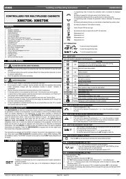
3.1 COMPRESSOR<br />
The regulation is performed Temper.<br />
according to the temperature<br />
measured by the thermostat probe SET<br />
with a positive differential from the<br />
set point: if the temperature<br />
Time<br />
increases and reaches set point plus Compr.<br />
differential the compressor is started ON<br />
and then turned off when the<br />
temperature reaches the set point<br />
value again.<br />
In case of fault in the thermostat probe the start and stop of the compressor are timed through<br />
parameters “COn” and “COF”.<br />
3.2 DEFROST<br />
Defrost is performed through a simple stop of the compressor. Parameter “IdF” controls the<br />
interval between defrost cycles, while its length is controlled by parameter “MdF”.<br />
: To display target set point; in programming mode it selects a parameter or confirm<br />
an operation.<br />
(DEF) To start a manual defrost<br />
(UP): To see the max. stored temperature; in programming mode it browses the<br />
parameter codes or increases the displayed value.<br />
(DOWN) To see the min stored temperature; in programming mode it browses the<br />
parameter codes or decreases the displayed value.<br />
To switch the instrument off, if onF = oFF.<br />
To switch the light, if oA1 = Lig<br />
KEY COMBINATIONS:<br />
+ To lock & unlock the keyboard.<br />
+ To enter in programming mode.<br />
+ To return to the room temperature display.<br />
4.1 USE OF LEDS<br />
Each LED function is described in the following table.<br />
LED MODE FUNCTION<br />
ON Compressor enabled<br />
Flashing<br />
ON<br />
ON<br />
ON<br />
ON<br />
ON<br />
ON<br />
°C/°F ON<br />
°C/°F Flashing<br />
Anti-short cycle delay enabled<br />
Defrost enabled<br />
An alarm is occurring<br />
Continuous cycle is running<br />
Energy saving enabled<br />
Light on<br />
Auxiliary relay on<br />
Measurement unit<br />
Programming phase<br />
5. MAX & MIN TEMPERATURE MEMORIZATION<br />
5.1 HOW TO SEE THE MIN TEMPERATURE<br />
1. Press and release the n key.<br />
2. The “Lo” message will be displayed followed by the minimum temperature recorded.<br />
3. By pressing the n key again or by waiting 5s the normal display will be restored.<br />
5.2 HOW TO SEE THE MAX TEMPERATURE<br />
1. Press and release the o key.<br />
2. The “Hi” message will be displayed followed by the maximum temperature recorded.<br />
3. By pressing the o key again or by waiting 5s the normal display will be restored.<br />
5.3 HOW TO RESET THE MAX AND MIN TEMPERATURE RECORDED<br />
1. Hold press the SET key for more than 3s, while the max. or min temperature is<br />
displayed. (rSt message will be displayed)<br />
2. To confirm the operation the “rSt” message starts blinking and the normal temperature<br />
will be displayed.<br />
6. MAIN FUNCTIONS<br />
6.1 HOW TO SEE THE SETPOINT<br />
1. Push and immediately release the SET key: the display will show<br />
the Set point value;<br />
2. Push and immediately release the SET key or wait for 5 seconds to<br />
display the probe value again.<br />
6.2 HOW TO CHANGE THE SETPOINT<br />
1. Push the SET key for more than 2 seconds to change the Set point value;<br />
2. The value of the set point will be displayed and the “°C” or “°F” LED starts blinking;<br />
3. To change the Set value push the o or n arrows within 10s.<br />
4. To memorise the new set point value push the SET key again or wait 10s.<br />
6.3 HOW TO START A MANUAL DEFROST<br />
Push the DEF key for more than 2 seconds and a manual defrost will<br />
start.<br />
1592020030 <strong>XR30CX</strong> GB m&M r1.1 05.03.2007.doc <strong>XR30CX</strong> 1/4
dIXEL Installing and Operating Instructions 1592020030<br />
6.4 HOW TO CHANGE A PARAMETER VALUE<br />
To change the parameter’s value operate as follows:<br />
1. Enter the Programming mode by pressing the Set + n keys for 3s (the “°C” or “°F” LED<br />
starts blinking).<br />
2. Select the required parameter. Press the “SET” key to display its value<br />
3. Use “UP” or “DOWN” to change its value.<br />
4. Press “SET” to store the new value and move to the following parameter.<br />
To exit: Press SET + UP or wait 15s without pressing a key.<br />
NOTE: the set value is stored even when the procedure is exited by waiting the time-out to<br />
expire.<br />
6.5 THE HIDDEN MENU<br />
The hidden menu Includes all the parameters of the instrument.<br />
6.5.1 HOW TO ENTER THE HIDDEN MENU<br />
1. Enter the Programming mode by pressing the Set + n keys for 3s (the “°C” or “°F” LED<br />
starts blinking).<br />
2. Released the keys, then push again the Set+n keys for more than 7s. The Pr2 label will<br />
be displayed immediately followed from the HY parameter.<br />
NOW YOU ARE IN THE HIDDEN MENU.<br />
3. Select the required parameter.<br />
4. Press the “SET” key to display its value<br />
5. Use o or n to change its value.<br />
6. Press “SET” to store the new value and move to the following parameter.<br />
To exit: Press SET + o or wait 15s without pressing a key.<br />
NOTE1: if none parameter is present in Pr1, after 3s the “noP” message is displayed. Keep<br />
the keys pushed till the Pr2 message is displayed.<br />
NOTE2: the set value is stored even when the procedure is exited by waiting the time-out to<br />
expire.<br />
6.5.2 HOW TO MOVE A PARAMETER FROM THE HIDDEN MENU TO<br />
THE FIRST LEVEL AND VICEVERSA.<br />
Each parameter present in the HIDDEN MENU can be removed or put into “THE FIRST<br />
LEVEL” (user level) by pressing “SET + n”.<br />
In HIDDEN MENU when a parameter is present in First Level the decimal point is on.<br />
6.6 HOW TO LOCK THE KEYBOARD<br />
1. Keep pressed for more than 3 s the UP + DOWN keys.<br />
2. The “POF” message will be displayed and the keyboard will be locked. At this point it will<br />
be possible only to see the set point or the MAX o Min temperature stored<br />
3. If a key is pressed more than 3s the “POF” message will be displayed.<br />
6.7 TO UNLOCK THE KEYBOARD<br />
Keep pressed together for more than 3s the o and n keys, till the “Pon” message will be<br />
displayed.<br />
6.8 THE CONTINUOUS CYCLE<br />
When defrost is not in progress, it can be activated by holding the “o” key pressed for about<br />
3 seconds. The compressor operates to maintain the “ccS” set point for the time set through<br />
the “CCt” parameter. The cycle can be terminated before the end of the set time using the<br />
same activation key “o” for 3 seconds.<br />
6.9 THE ON/OFF FUNCTION<br />
With “onF = oFF”, pushing the ON/OFF key, the instrument is switched off. The<br />
“OFF” message is displayed. In this configuration, the regulation is disabled.<br />
To switch the instrument on, push again the ON/OFF key.<br />
WARNING: Loads connected to the normally closed contacts of the relays are always<br />
supplied and under voltage, even if the instrument is in stand by mode.<br />
7. PARAMETERS<br />
REGULATION<br />
Hy Differential: (0,1 ÷ 25,5°C / 1÷255 °F) Intervention differential for set point. Compressor<br />
Cut IN is Set Point + differential (Hy). Compressor Cut OUT is when the temperature<br />
reaches the set point.<br />
LS Minimum set point: (- 50°C÷SET/-58°F÷SET): Sets the minimum value for the set point.<br />
US Maximum set point: (SET÷110°C/ SET÷230°F). Set the maximum value for set point.<br />
Ot Thermostat probe calibration: (-12.0÷12.0°C; -120÷120°F) allows to adjust possible<br />
offset of the thermostat probe.<br />
P3P Third probe presence (P3): n= not present:, the terminal operates as digital input.; y=<br />
present:, the terminal operates as third probe.<br />
O3 Third probe calibration (P3): (-12.0÷12.0°C; -120÷120°F). allows to adjust possible<br />
offset of the third probe.<br />
P4P Fourth probe presence: (n = Not present; y = present).<br />
o4 Fourth probe calibration: (-12.0÷12.0°C) allows to adjust possible offset of the fourth<br />
probe.<br />
OdS Outputs activation delay at start up: (0÷255min) This function is enabled at the initial<br />
start up of the instrument and inhibits any output activation for the period of time set in<br />
the parameter.<br />
AC Anti-short cycle delay: (0÷50 min) minimum interval between the compressor stop and<br />
the following restart.<br />
CCt Compressor ON time during continuous cycle: (0.0÷24.0h; res. 10min) Allows to set<br />
the length of the continuous cycle: compressor stays on without interruption for the CCt<br />
time. Can be used, for instance, when the room is filled with new products.<br />
CCS Set point for continuous cycle: (-50÷150°C) it sets the set point used during the<br />
continuous cycle.<br />
COn Compressor ON time with faulty probe: (0÷255 min) time during which the<br />
compressor is active in case of faulty thermostat probe. With COn=0 compressor is always<br />
OFF.<br />
COF Compressor OFF time with faulty probe: (0÷255 min) time during which the<br />
compressor is OFF in case of faulty thermostat probe. With COF=0 compressor is always<br />
active.<br />
CH Type of action: CL = cooling; Ht = heating.<br />
DISPLAY<br />
CF Temperature measurement unit: °C=Celsius; °F=Fahrenheit. WARNING: When the<br />
measurement unit is changed the SET point and the values of the parameters Hy, LS,<br />
US, Ot, ALU and ALL have to be checked and modified if necessary).<br />
rES Resolution (for °C): (in = 1°C; dE = 0.1 °C) allows decimal point display.<br />
dLy Display delay: (0 ÷20.0m; risul. 10s) when the temperature increases, the display is<br />
updated of 1 °C/1°F after this time.<br />
DEFROST<br />
IdF Interval between defrost cycles: (0÷120h) Determines the time interval between the<br />
beginning of two defrost cycles.<br />
MdF (Maximum) length for defrost: (0÷255min) When P2P = n, (not evaporator probe:<br />
timed defrost) it sets the defrost duration, when P2P = y (defrost end based on<br />
temperature) it sets the maximum length for defrost.<br />
dFd Temperature displayed during defrost: (rt = real temperature; it = temperature at<br />
defrost start; SEt = set point; dEF = “dEF” label)<br />
dAd MAX display delay after defrost: (0÷255min). Sets the maximum time between the end<br />
of defrost and the restarting of the real room temperature display.<br />
ALARMS<br />
ALC Temperature alarms configuration: (Ab; rE)<br />
Ab= absolute temperature: alarm temperature is given by the ALL or ALU values. rE =<br />
temperature alarms are referred to the set point. Temperature alarm is enabled when the<br />
temperature exceeds the “SET+ALU” or “SET-ALL” values.<br />
ALU MAXIMUM temperature alarm: (SET÷110°C; SET÷230°F) when this temperature is<br />
reached the alarm is enabled, after the “ALd” delay time.<br />
ALL Minimum temperature alarm: (-50.0 ÷ SET°C; -58÷230°F when this temperature is<br />
reached the alarm is enabled, after the “ALd” delay time.<br />
AFH Differential for temperature alarm recovery: (0,1÷25,5°C; 1÷45°F) Intervention<br />
differential for recovery of temperature alarm.<br />
ALd Temperature alarm delay: (0÷255 min) time interval between the detection of an alarm<br />
condition and alarm signalling.<br />
dAO Exclusion of temperature alarm at startup: (from 0.0 min to 23.5h) time interval<br />
between the detection of the temperature alarm condition after instrument power on and<br />
alarm signalling.<br />
CONDENSER TEMPERATURE ALARM (detected by the fourth probe)<br />
AP2 Probe selection for temperature alarm of condenser: nP = no probe; P1 =thermostat<br />
probe; P2 = evaporator probe; P3 =configurable probe; P4 = Probe on Hot Key plug.<br />
AL2 Low temperature alarm of condenser: (-55÷150°C) when this temperature is reached<br />
the LA2 alarm is signalled, possibly after the Ad2 delay.<br />
Au2 High temperature alarm of condenser: (-55÷150°C) when this temperature is reached<br />
the HA2 alarm is signalled, possibly after the Ad2 delay.<br />
AH2 Differential for temperature condenser alarm recovery: (0,1÷25,5°C; 1÷45°F)<br />
Ad2 Condenser temperature alarm delay: (0÷255 min) time interval between the detection<br />
of the condenser alarm condition and alarm signalling.<br />
dA2 Condenser temperature alarm exclusion at start up: (from 0.0 min to 23.5h, res.<br />
10min)<br />
bLL Compressor off with low temperature alarm of condenser: n = no: compressor<br />
keeps on working; Y = yes, compressor is switched off till the alarm is present, in any<br />
case regulation restarts after AC time at minimum.<br />
AC2 Compressor off with high temperature alarm of condenser: n = no: compressor<br />
keeps on working; Y = yes, compressor is switched off till the alarm is present, in any<br />
case regulation restarts after AC time at minimum.<br />
SECOND RELAY<br />
tbA Alarm relay silencing (with oA1=ALr):<br />
(n= silencing disabled: alarm relay stays on till alarm condition lasts, y =silencing<br />
enabled: alarm relay is switched OFF by pressing a key during an alarm).<br />
oA1 Second relay configuration: ALr: alarm; Lig: light; AuS: Auxiliary relay; onF: always<br />
on with instrument on; db = do not select it; dEF: do not select it!.; FAn: do not select<br />
it!.; dF2: do not select it.<br />
AoP Alarm relay polarity: it set if the alarm relay is open or closed when an alarm happens.<br />
CL= terminals 1-2 closed during an alarm; oP = terminals 1-2 open during an alarm<br />
DIGITAL INPUT<br />
i1P Digital input polarity: oP: the digital input is activated by opening the contact; CL: the<br />
digital input is activated by closing the contact.<br />
i1F Digital input configuration: EAL = external alarm: “EA” message is displayed; bAL =<br />
serious alarm “CA” message is displayed. PAL = pressure switch alarm, “CA” message<br />
is displayed; dor = door switch function; dEF = activation of a defrost cycle; AUS =to<br />
switch on the second relay if oA1 = AUS; Htr = kind of action inversion (cooling –<br />
heating); FAn = not set it; ES = Energy saving.<br />
did: (0÷255 min) with i1F= EAL or i1F = bAL digital input alarm delay: delay between the<br />
detection of the external alarm condition and its signalling.<br />
with i1F= dor: door open signalling delay<br />
with i1F = PAL: time for pressure switch function: time interval to calculate the<br />
number of the pressure switch activation.<br />
1592020030 <strong>XR30CX</strong> GB m&M r1.1 05.03.2007.doc <strong>XR30CX</strong> 2/4
dIXEL Installing and Operating Instructions 1592020030<br />
nPS Pressure switch number: (0 ÷15) Number of activation of the pressure switch, during<br />
the “did” interval, before signalling the alarm event (I2F= PAL).<br />
If the nPS activation in the did time is reached, switch off and on the instrument to<br />
restart normal regulation.<br />
odc Compressor status with door open: no, Fan = normal; CPr; F_C = Compressor OFF.<br />
rrd Outputs restart after doA alarm: no = outputs not affected by the doA alarm; yES =<br />
outputs restart with the doA alarm;<br />
HES Temperature increase during the Energy Saving cycle : (-30,0°C÷30,0°C/-22÷86°F)<br />
it sets the increasing value of the set point during the Energy Saving cycle.<br />
OTHER<br />
Adr Serial address (1÷244): Identifies the instrument address when connected to a<br />
ModBUS compatible monitoring system.<br />
PbC Type of probe: it allows to set the kind of probe used by the instrument: PbC = PBC<br />
probe, ntc = NTC probe.<br />
onF on/off key enabling: nu = disabled; oFF = enabled; ES = not set it.<br />
dP1 Thermostat probe display<br />
dP3 Third probe display- optional.<br />
dP4 Fourth probe display.<br />
rSE Real set point: (readable only), it shows the set point used during the energy saving<br />
cycle or during the continuous cycle.<br />
rEL Software release for internal use.<br />
Ptb Parameter table code: readable only.<br />
8. DIGITAL INPUT (ENABLED WITH P3P = N)<br />
The free voltage digital input is programmable in different configurations by the “i1F”<br />
parameter.<br />
8.1 DOOR SWITCH INPUT (i1F = dor)<br />
It signals the door status and the corresponding relay output status through the “odc”<br />
parameter: no, Fan = normal (any change); CPr, F_C = Compressor OFF.<br />
Since the door is opened, after the delay time set through parameter “did”, the door alarm is<br />
enabled, the display shows the message “dA” and the regulation restarts is rtr = yES. The<br />
alarm stops as soon as the external digital input is disabled again. With the door open, the<br />
high and low temperature alarms are disabled.<br />
8.2 GENERIC ALARM (i1F = EAL)<br />
As soon as the digital input is activated the unit will wait for “did” time delay before signalling<br />
the “EAL” alarm message. The outputs status don’t change. The alarm stops just after the<br />
digital input is de-activated.<br />
8.3 SERIOUS ALARM MODE (i1F = bAL)<br />
When the digital input is activated, the unit will wait for “did” delay before signalling the “CA”<br />
alarm message. The relay outputs are switched OFF. The alarm will stop as soon as the<br />
digital input is de-activated.<br />
8.4 PRESSURE SWITCH (i1F = PAL)<br />
If during the interval time set by “did” parameter, the pressure switch has reached the number<br />
of activation of the “nPS” parameter, the “CA” pressure alarm message will be displayed. The<br />
compressor and the regulation are stopped. When the digital input is ON the compressor is<br />
always OFF.<br />
If the nPS activation in the did time is reached, switch off and on the instrument to<br />
restart normal regulation.<br />
8.5 START DEFROST (i1F = dFr)<br />
It starts a defrost if there are the right conditions. After the defrost is finished, the normal<br />
regulation will restart only if the digital input is disabled otherwise the instrument will wait until<br />
the “MdF” safety time is expired.<br />
8.6 INVERSION OF THE KIND OF ACTION: HEATING-COOLING (i1F = Htr)<br />
This function allows to invert the regulation of the controller: from cooling to heating and<br />
viceversa.<br />
8.7 ENERGY SAVING (i1F = ES)<br />
The Energy Saving function allows to change the set point value as the result of the SET+<br />
HES (parameter) sum. This function is enabled until the digital input is activated.<br />
8.8 DIGITAL INPUTS POLARITY<br />
The digital input polarity depends on the “i1P” parameter.<br />
i1P=CL: the input is activated by closing the contact.<br />
i1P=OP: the input is activated by opening the contact<br />
9. TTL SERIAL LINE – FOR MONITORING SYSTEMS<br />
The TTL serial line, available through the HOT KEY connector, allows by means of the<br />
external TTL/RS485 converter, XJ485-CX, to connect the instrument to a monitoring system<br />
ModBUS-RTU compatible such as the X-WEB500/3000/300.<br />
10. X-REP OUTPUT – OPTIONAL<br />
As optional, an X-REP can be connected to the instrument, trough the HOY<br />
KEY connector. The X-REP output EXCLUDES the serial connection.<br />
To connect the X-REP to the<br />
instrument the following<br />
connectors must be used CAB-<br />
51F(1m), CAB-52F(2m), CAB-<br />
55F(5m),<br />
11. INSTALLATION AND MOUNTING<br />
Instrument <strong>XR30CX</strong> shall be mounted on vertical panel, in a<br />
29x71 mm hole, and fixed using the special bracket supplied.<br />
The temperature range allowed for correct operation is 0÷60<br />
°C. Avoid places subject to strong vibrations, corrosive<br />
gases, excessive dirt or humidity. The same<br />
recommendations apply to probes. Let air circulate by the<br />
cooling holes.<br />
12. ELECTRICAL CONNECTIONS<br />
The instrument is provided with screw terminal block to connect cables with a cross section up<br />
to 2,5 mm 2 . Before connecting cables make sure the power supply complies with the<br />
instrument’s requirements. Separate the probe cables from the power supply cables, from the<br />
outputs and the power connections. Do not exceed the maximum current allowed on each<br />
relay, in case of heavier loads use a suitable external relay.<br />
12.1 PROBE CONNECTION<br />
The probes shall be mounted with the bulb upwards to prevent damages due to casual liquid<br />
infiltration. It is recommended to place the thermostat probe away from air streams to correctly<br />
measure the average room temperature. Place the defrost termination probe among the<br />
evaporator fins in the coldest place, where most ice is formed, far from heaters or from the<br />
warmest place during defrost, to prevent premature defrost termination.<br />
13. HOW TO USE THE HOT KEY<br />
13.1 HOW TO PROGRAM A HOT KEY FROM THE INSTRUMENT (UPLOAD)<br />
1. Program one controller with the front keypad.<br />
2. When the controller is ON, insert the “Hot key” and push o key; the "uPL" message<br />
appears followed a by flashing “End”<br />
3. Push “SET” key and the End will stop flashing.<br />
4. Turn OFF the instrument remove the “Hot Key”, then turn it ON again.<br />
NOTE: the “Err” message is displayed for failed programming. In this case push again o key<br />
if you want to restart the upload again or remove the “Hot key” to abort the operation.<br />
13.2 HOW TO PROGRAM AN INSTRUMENT USING A HOT KEY<br />
(DOWNLOAD)<br />
1. Turn OFF the instrument.<br />
2. Insert a programmed “Hot Key” into the 5 PIN receptacle and then turn the<br />
Controller ON.<br />
3. Automatically the parameter list of the “Hot Key” is downloaded into the Controller<br />
memory, the “doL” message is blinking followed a by flashing “End”.<br />
4. After 10 seconds the instrument will restart working with the new parameters.<br />
5. Remove the “Hot Key”..<br />
NOTE the message “Err” is displayed for failed programming. In this case turn the unit off and<br />
then on if you want to restart the download again or remove the “Hot key” to abort the<br />
operation.<br />
14. ALARM SIGNALS<br />
Message Cause Outputs<br />
“P1” Room probe failure Compressor output acc. to par. “Con” and<br />
“COF”<br />
“P3” Third probe failure Outputs unchanged<br />
“P4” Fourth probe failure Outputs unchanged<br />
“HA” Maximum temperature alarm Outputs unchanged.<br />
“LA” Minimum temperature alarm Outputs unchanged.<br />
"HA2" Condenser high temperature It depends on the “Ac2” parameter<br />
"LA2" Condenser low temperature It depends on the “bLL” parameter<br />
“dA” Door open Compressor according to rrd<br />
“EA” External alarm Output unchanged.<br />
“CA” Serious external alarm All outputs OFF.<br />
(i1F=bAL)<br />
“CA” Pressure switch alarm All outputs OFF<br />
(i1F=PAL)<br />
14.1 ALARM RECOVERY<br />
Probe alarms P1”, “P3” and “P4” start some seconds after the fault in the related probe; they<br />
automatically stop some seconds after the probe restarts normal operation. Check<br />
connections before replacing the probe.<br />
Temperature alarms “HA”, “LA” “HA2” and “LA2” automatically stop as soon as the<br />
temperature returns to normal values.<br />
Alarms “EA” and “CA” (with i1F=bAL) recover as soon as the digital input is disabled.<br />
Alarm “CA” (with i1F=PAL) recovers only by switching off and on the instrument.<br />
14.2 OTHER MESSAGES<br />
1592020030 <strong>XR30CX</strong> GB m&M r1.1 05.03.2007.doc <strong>XR30CX</strong> 3/4<br />
Pon<br />
PoF<br />
noP<br />
noA<br />
Keyboard unlocked.<br />
Keyboard locked<br />
In programming mode: none parameter is present in Pr1<br />
On the display or in dP2, dP3, dP4: the selected probe is nor enabled<br />
None alarm is recorded.
dIXEL Installing and Operating Instructions 1592020030<br />
15. TECHNICAL DATA<br />
Housing: self extinguishing ABS.<br />
Case: <strong>XR30CX</strong> frontal 32x74 mm; depth 60mm;<br />
Mounting: <strong>XR30CX</strong> panel mounting in a 71x29mm panel cut-out<br />
Protection: IP20; Frontal protection: <strong>XR30CX</strong> IP65<br />
Connections: Screw terminal block ≤ 2,5 mm 2 wiring.<br />
Power supply: according to the model: 12Vac/dc, ±10%; 24Vac/dc, ±10%; 230Vac ±10%,<br />
50/60Hz, 110Vac ±10%, 50/60Hz<br />
Power absorption: 3VA max<br />
Display: 3 digits, red LED, 14,2 mm high; Inputs: Up to 4 NTC or PTC probes.<br />
Digital input: free voltage contact<br />
Relay outputs: compressor SPST 8(3) A, 250Vac; or 20(8)A 250Vac<br />
AUX: SPDT 8(3) A, 250Vac<br />
Data storing: on the non-volatile memory (EEPROM).<br />
Kind of action: 1B; Pollution grade: 2;Software class: A.;<br />
Rated impulsive voltage: 2500V; Overvoltage Category: II<br />
Operating temperature: 0÷60 °C;Storage temperature: -30÷85 °C.<br />
Relative humidity: 20÷85% (no condensing)<br />
Measuring and regulation range: NTC probe: -40÷110°C (-40÷230°F);<br />
PTC probe: -50÷150°C (-58÷302°F)<br />
Resolution: 0,1 °C or 1°C or 1 °F (selectable); Accuracy (ambient temp. 25°C): ±0,7 °C<br />
±1 digit<br />
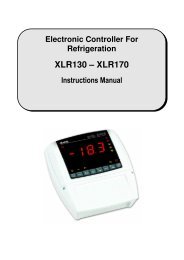
16. CONNECTIONS<br />
The X-REP output excludes the TTL output.. It’s present in the following codes:<br />
<strong>XR30CX</strong>- xx2xx, <strong>XR30CX</strong> –xx3xx;<br />
16.1 <strong>XR30CX</strong> – 8A COMPRESSOR<br />
Line<br />
8(3)A250V<br />
1 2 3 4 5 6 7<br />
Light/<br />
N.C.<br />
Alarm<br />
8(3)A250V<br />
Comp<br />
12Vac/dc supply: connect to the terminals 7 and 8.<br />
24Vac/dc supply: connect to the terminals 7 and 8.<br />
120Vac supply: connect to the terminals 7 and 8.<br />
16.2 <strong>XR30CX</strong> – 20A COMPRESSOR<br />
Line<br />
8(3)A250V<br />
1 2 3 4 5 6 7<br />
Light/<br />
N.C.<br />
Alarm<br />
20(8)A250V<br />
Comp<br />
12Vac/dc supply: connect to the terminals 7 and 8.<br />
24Vac/dc supply: connect to the terminals 7 and 8.<br />
120Vac supply: connect to the terminals 7 and 8.<br />
8<br />
8<br />
9 10 11 12<br />
Room<br />
Hot Key/IV probe<br />
TTL or X-REP output<br />
9 10 11 12<br />
Room<br />
Hot Key/IV probe<br />
TTL or X-REP output<br />
rES Resolution in=integer; dE= dec.point dE Pr1<br />
dLy Display temperature delay 0 ÷ 20.0 min (10 sec.) 0 Pr2<br />
IdF Interval between defrost cycles 1 ÷ 120 ore 8 Pr1<br />
MdF (Maximum) length for defrost 0 ÷ 255 min 20 Pr1<br />
dFd Displaying during defrost rt, it, SEt, DEF it Pr2<br />
dAd MAX display delay after defrost 0 ÷ 255 min 30 Pr2<br />
ALc Temperat. alarms configuration<br />
rE= related to set;<br />
Ab = absolute<br />
Ab Pr2<br />
ALU MAXIMUM temperature alarm Set÷110.0°C; Set÷230°F 110 Pr1<br />
ALL Minimum temperature alarm -50.0°C÷Set/ -58°F÷Set -50.0 Pr1<br />
AFH Differential for temperat. alarm (0,1°C÷25,5°C) (1°F÷45°F)<br />
recovery<br />
1 Pr2<br />
ALd Temperature alarm delay 0 ÷ 255 min 15 Pr2<br />
dAo Delay of temperature alarm at start up 0 ÷ 23h e 50’ 1.3 Pr2<br />
AP2 Probe for temperat. alarm of<br />
nP; P1; P2; P3; P4<br />
condenser<br />
P4 Pr2<br />
AL2 Condenser for low temperat. alarm (-55 ÷ 150°C) (-67÷ 302°F) -40 Pr2<br />
AU2 Condenser for high temperat. alarm (-55 ÷ 150°C) (-67÷ 302°F) 110 Pr2<br />
Differ. for condenser temp. alar. [0,1°C ÷ 25,5°C] [1°F ÷<br />
AH2 recovery<br />
45°F]<br />
5 Pr2<br />
Ad2 Condenser temperature alarm delay 0 ÷ 254 (min.) , 255=nU 15 Pr2<br />
Delay of cond. temper. alarm at start<br />
dA2 up 0.0 ÷ 23h 50’<br />
1,3 Pr2<br />
Compr. off for condenser low<br />
bLL temperature alarm<br />
n(0) - Y(1)<br />
n Pr2<br />
Compr. off for condenser high<br />
AC2 temperature alarm<br />
n(0) - Y(1)<br />
n Pr2<br />
tbA Alarm relay disabling n=no; y=yes y Pr2<br />
oA1 2 nd relay configuration<br />
ALr = alarm; dEF = do not<br />
select it; Lig =Light; AUS<br />
=AUX; onF=always on; Fan= Lig Pr2<br />
do not select it; db = do not<br />
select it; dF2 = do not select it<br />
AoP Alarm relay polarity (oA1=ALr) oP; cL cL Pr2<br />
i1P Digital input polarity oP=opening;CL=closing cL Pr1<br />
i1F Digital input configuration<br />
EAL, bAL, PAL, dor; dEF; Htr,<br />
AUS<br />
dor Pr1<br />
did Digital input alarm delay 0÷255min 15 Pr1<br />
nPS Number of activation of pressure<br />
0 ÷15<br />
switch<br />
15 Pr2<br />
odc Compress status when open door no; Fan; CPr; F_C no Pr2<br />
rrd Regulation restart with door open<br />
n – Y<br />
alarm<br />
y Pr2<br />
HES Differential for Energy Saving (-30°C÷30°C) (-54°F÷54°F) 0 Pr2<br />
Adr Serial address 0÷247 1 Pr2<br />
PbC Kind of probe Ptc; ntc ntc Pr1<br />
onF on/off key enabling nu, oFF; ES nu Pr2<br />
dP1 Room probe display -- -- Pr2<br />
dP3 Third probe display -- -- Pr1<br />
dP4 Fourth probe display -- -- Pr1<br />
rSE Real set point value actual set -- Pr2<br />
rEL Software release -- -- Pr2<br />
Ptb Map code -- -- Pr2<br />
17. DEFAULT SETTING VALUES<br />
Labe Name Range °C/°F<br />
Set Set point LS÷US 3.0 - - -<br />
Hy Differential 0,1÷25.5°C/ 1÷ 255°F 2.0 Pr1<br />
LS Minimum set point -50°C÷SET/-58°F÷SET -50.0 Pr2<br />
US Maximum set point SET÷110°C/ SET ÷ 230°F 110 Pr2<br />
Ot Thermostat probe calibration -12÷12°C /-120÷120°F 0.0 Pr1<br />
P3P Third probe presence n=not present; Y=pres. n Pr2<br />
O3 Third probe calibration -12÷12°C /-120÷120°F 0 Pr2<br />
P4P Fourth probe presence n=not present; Y=pres. n Pr2<br />
O4 Fourth probe calibration -12÷12°C /-120÷120°F 0 Pr2<br />
OdS Outputs delay at start up 0÷255 min 0 Pr2<br />
AC Anti-short cycle delay 0 ÷ 50 min 1 Pr1<br />
CCt Continuos cycle duration 0.0÷24.0h 0.0 Pr2<br />
CC Set point for continuous cycle (-55.0÷150,0°C) (-67÷302°F)<br />
S<br />
3 Pr2<br />
CO Compressor ON time with faulty probe 0 ÷ 255 min<br />
n<br />
15 Pr2<br />
CO Compressor OFF time with faulty 0 ÷ 255 min<br />
F probe<br />
30 Pr2<br />
CH Kind of action CL=cooling; Ht= heating cL Pr1<br />
CF Temperature measurement unit °C ÷ °F °C Pr2<br />
Dixell S.p.A. Z.I. Via dell’Industria, 27<br />
32010 Pieve d’Alpago (BL) ITALY<br />
tel. +39 - 0437 - 98 33 - fax +39 - 0437 - 98 93 13<br />
E-mail: dixell@dixell.com - http://www.dixell.com<br />
1592020030 <strong>XR30CX</strong> GB m&M r1.1 05.03.2007.doc <strong>XR30CX</strong> 4/4