SECTION 13921 ELECTRIC-DRIVE, CENTRIFUGAL FIRE PUMPS
SECTION 13921 ELECTRIC-DRIVE, CENTRIFUGAL FIRE PUMPS
SECTION 13921 ELECTRIC-DRIVE, CENTRIFUGAL FIRE PUMPS
You also want an ePaper? Increase the reach of your titles
YUMPU automatically turns print PDFs into web optimized ePapers that Google loves.
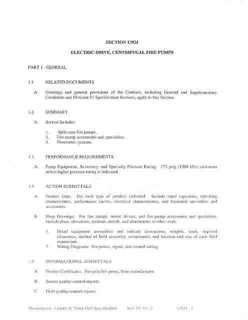
<strong>SECTION</strong> <strong>13921</strong><br />
<strong>ELECTRIC</strong>-<strong>DRIVE</strong>, <strong>CENTRIFUGAL</strong> <strong>FIRE</strong> <strong>PUMPS</strong><br />
PART I - GENERAL<br />
Ll<br />
RELATED DOCUMENTS<br />
A. Drawings and general provisions of the Contract, including General and Supplementary<br />
Conditions and Division 01 Specification Sections, apply to this Section.<br />
1.2 SUMMARY<br />
A. Section Includes:<br />
I. Split-case fire pumps.<br />
2. Fire-pump accessories and specialties.<br />
3. Flowmeter systems.<br />
1.3 PERFORMANCE REQUIREMENTS<br />
A. Pump Equipment, Accessory, and Specialty Pressure Rating: 175 psig (1200 kPa) minimum<br />
Uil1css higher pressure rating is indicated.<br />
1.4 ACTION SUBMITfALS<br />
A. Product Data: For each type of product indicated. Include rated CapaCitieS, operating<br />
characteristics, performance curves, electrical characteristics, and furnished specialties and<br />
accessories.<br />
B. Shop Drawings: For fire pumps, motor drivers, and fire-pump accessories and spccialties.<br />
Include plans, elevations, sections, details. and attachments to other work.<br />
I. Detail equipment assemblies and indicate dimcnsions, weights, loads, reCJuireu<br />
clearances, method of field assembly, components, and location and size of each field<br />
connection.<br />
') Wiring Diagrams: For power, signaL and control wiring.<br />
1.5 INFORMATIONAL SUBMITTALS<br />
A. Product Certificates: For each fire pump, from manufacturer.<br />
B. Source quality-control reports.<br />
C. Field quality-control rcports.<br />
fvlOlllcstov,'n .. Libr"ry & Town 1[,,11 Spccific;\tioll Rev. 0)-1 (J·12 I ~,l)2 I . I
1.6 CLOSEOUr SUBMITTALS<br />
A. Operation and Mmntenance Data: For fire pumps to include in operation and maintenance<br />
manuals.<br />
1.7 QUALITY ASSURANCE<br />
A. Electrical Components, Devices, and Accessories: Listed and labeled as defined in NFPA 70,<br />
by a qualified testing agency, and marked for intended location and application.<br />
n. NFPA Compliance: Comply with NFPA 20, "Installation of Stationary Pumps for Fire<br />
Protection."<br />
1.8 COORDiNATION<br />
A. Coordinate sizes and locations of concrete bases with actual equipment provided.<br />
PART 2 - PRODUCTS<br />
2.1<br />
HORIZONTALLY MOUNTED, SINGLE-STAGE, SPLIT-CASE <strong>FIRE</strong> <strong>PUMPS</strong><br />
A.<br />
Manufacturers: Subject to compliance with requirements, Sec sprinkler drawing for fire<br />
spririklerpump specified or approved equal:<br />
1.<br />
2.<br />
3.<br />
4.<br />
S.<br />
6.<br />
7.<br />
8.<br />
9.<br />
A-C Fire Pump Systems: a business of fIT Industries.<br />
Corcoran Piring System CQ.<br />
Patterson Pump Company; a subsidiary of the Gorman-Rupp COmp_
C. Coupling: Flexible and capable of absorbing torsional vibration and shaft misalignment.<br />
Include metal coupling guard.<br />
D. Driver:<br />
I. Standard: UL 1004A.<br />
2. Type: Electric motor; NEMA MG I, polyphase Design B.<br />
E. Capacities and Characteristics:<br />
]. See sprinkler drawings for firc sprinkler pump specification..<br />
2.2<br />
A.<br />
<strong>FIRE</strong>-PUMP ACCESSORIES AND SPECIALTIES<br />
Automatic Air-Release Valves: Comply with NFPA 20 for installation in fire-pump casing.<br />
B.<br />
c.<br />
Circulation Reljcf Valves:<br />
piping.<br />
Relief Valves:<br />
UL 1478, brass, spring loaded; for installation in pump discharge<br />
]. Manufacturers: Subject to compliance with requirements, provide products by one of the<br />
following or approved equal:<br />
a. BERMAD Control Valves.<br />
b. CLA-VAL Automatic Control Valves.<br />
c. KuhkleValve;a partofTyco International Ltd.<br />
d. OCVControLViUyes.<br />
e. -,:Y
. Body: Flush typc, brass or ductile iron, with number of outlets required by<br />
NFPA 20.<br />
c. Nipples: ASlM A 53/A 53M, Schedule 40, galvanized-steel pipe with ends<br />
threaded according to ASME B 1.20.1.<br />
d. Adapters and Caps with Chain: Brass or bronze, with outlet threaded according to<br />
NFPA 1963 and matching local fire-department threads.<br />
e. Escutcheon Plate: Brass or bronzc; rectangular.<br />
f. Hose Valves: UL 668, bronze, with outlet threaded according to NFPA 1963 and<br />
matching local fire-department threads.<br />
g. Exposed Parts Finish: Rough.<br />
h. Escutcheon Plate Marking: Equivalent to "<strong>FIRE</strong> PUMP TEST."<br />
6. Manifold:<br />
a. Test Connections: Comply with UL 405 except provide outlets without clappers<br />
instead of inlets.<br />
b. Body: Exposed type, brass, with number of outlets required by NFPA 20.<br />
c. Escutcheon Plate: Brass or bronze; round.<br />
d. Hose Valves: l1L 668, bronze, with outlet threaded according to NFPA 1963 and<br />
matching local fire-department threads. Include caps and chains.<br />
e. Exposed Parts Finish: Rough.<br />
f. Escutcheon Plate Marking: Equivalent to "<strong>FIRE</strong> PUMP TEST."<br />
2.3<br />
A.<br />
B.<br />
FLOWMETER SYSTEMS<br />
Manufacturers: Subject to compliance with requirements, provide products by one of the<br />
following or approved equal:<br />
Basis~of-Design Product: . Subject to cOlnpliance with requirements, provide or comparable<br />
product byorie of the following:<br />
I. Emerson Process_Malia~Jllent:Rosemount Division.<br />
2. Fire Rescarcl] Com.<br />
3. Gerand Engine~ringCo.<br />
4. l:IyclrQ_.FIQ-"~. Products, Inc.<br />
5. Hyspan Precision Products. Inc.<br />
6. Mcriam Process Tcchnolo~~ies.<br />
7. Preso Meters: Division Qf Racine Federated ID~.<br />
8. K~QQ:y':BuffaloQ.s_rJ.t.tnR Company.<br />
9. Victauli~J:;;ompany.<br />
C. Description: UL,-listco or FM-Approyco, fire-pump flowmeter system with capability to<br />
indicate now to not less than 17S percent of fire-pump rated capacity.<br />
D. Pressure Rating: 175 psig (1200 kPa) minimum.<br />
E. Sensor: Annubar probe, orifice plate, or venturi unless otherwise indicated. Sensor size shall<br />
match pipe, tubing, flowmeter, and fittings.<br />
(\/looresloWll - Library & Towil ! I;t11 Specification I
F. Permanently Mounted Flowmeter: Compatible with flow sensor; with dial not less than 4-1/2<br />
inches (J 15 mm) in diameter. Include bracket or device for wall mounting.<br />
1. Tubing Package: NPS 1/4 ( DN 10) soft copper tubing with copper or brass fittings and<br />
valves.<br />
G. Portable Flowmeter: Compatible with flow sensor; with dial not less than 4-]12 inches (lIS<br />
mm) in diameter and with two 12-foot- (3.7-m-) long hoses in carrying case.<br />
2.4 GROUT<br />
A. Standard: ASTM C 1107, Grade B, post-hardening and volume-adjusting, dry, hydrauliccement<br />
grollt.<br />
B. Characteristics: Nonshrink and recommended for interior and exterior applications.<br />
C. Design Mix: SOOO-psi (34-MPa), 28-day compressive strength.<br />
D. Packaging: Premixed and factory packaged.<br />
2.5 SOURCE QUALITY CONTROL<br />
A. Testing: Test and inspect fire pumps according to UL 448 requirements for "Operation Test"<br />
and "Manufacturing and Production Tests."<br />
I. Verification ofPcrfonnzmcc: Rate fire pumps according to UL 448.<br />
B. Fire pumps will be considered defective if they do not pass tests and inspections.<br />
C. Prepare test and inspection rcports.<br />
PART 3 -EXECUTION<br />
3.1<br />
EXAMINATION<br />
A.<br />
B.<br />
c.<br />
Examine equipment bases ancl anchorage provisions, with Installer prescnt. for compliance with<br />
requirements and for conditions affecting performancc of fire pumps.<br />
Examine roughing-in for fire-suppression piping systems to verify actual locations of piping<br />
conncctions bcfore [Ire-pump installation.<br />
Proceed with installation only aftcr unsatisfactory conditions havc bccn corrccted.<br />
3.2<br />
INSTALLATION<br />
A.<br />
Fire-Pump Installation Standard:<br />
valvcs, ancl rebted components.<br />
Comply with NFPA 20 for installation of fire pumps, relicf<br />
l'v!oeJi'cs[own - L,ibrary & TuwnHaJI Specification Rev. 07 10·12 \)')21 ')
B. Equipment Mounting:<br />
1. Install fire pumps on cast-in-place concrete equipment bases. Comply with requirements<br />
for equipment bases and foundations specified in Section 03300 "Cast-in-Place<br />
Concrete."<br />
2. Comply with requirements for vibration isolation and seismic control devices specified in<br />
Section 15072 "Vibration and Seismic Controls for Fire-Suppression Piping and<br />
EquipmenL"<br />
3. Comply with requirements for vibration isolation devices specified in Section 15071<br />
"Vibration Controls for Fire-Suppression Piping and Equipment."<br />
C. Install fire-pump suction and discharge piping equal to or larger than sizes required by<br />
NFPA 20.<br />
D. Support piping and pumps separately so weight of piping does not rest on pumps.<br />
E. Install valves that are same size as connecting piping. Comply with requirements for fireprotection<br />
valves specified in Section 13930 "Wet-Pipe Fire-Suppression Sprinklers."<br />
F. Install pressure gages on fire-pump suction and discharge flange pressure-gage tappings.<br />
Comply with requirements for pressure gages specified in Section 13930 "Wet-Pipe Fire<br />
Suppression Sprinklers."<br />
G. Install piping hangers ancI supports, ancbors, valves, gages, and equipment supports according<br />
.. to NFPA 20.<br />
H. Instal1flowmeters and sensors. Install flowmeter-system components and make connections<br />
according to NFPA 20 arid manufacturer's written instructions.<br />
L<br />
EJectrical \Viri ng:<br />
faCtory mounted.<br />
Installer.<br />
Install electrical devices furnished by equipment manufacturers but not<br />
Furnish copies of manufacturers' wiring diagram submittals to elcctrical<br />
J.<br />
Wiring Method:<br />
possible.<br />
Conceal conductors and cables in accessible ceilings, walls, and floors where<br />
3.3<br />
ALIGNMENT<br />
A.<br />
B.<br />
c.<br />
D.<br />
Align split-case pUl11p and driver shafts after complete unit has bccn Ievcled on concrete base,<br />
grout has set, and anchor bolts have been tightencd.<br />
After alignment is correct, tighten anchor bolts evcnly. Fill b,lseplate completely with grout,<br />
with metal blocks and shims or wedges in place. Tighten anchor bolts after grout has hardcned.<br />
Check alignment and make required corrections.<br />
Align piping connections.<br />
Align pump and driver shafts for angular and paralIcI alignment according to HI 1.4 and to<br />
tolerances specified by manufacturer.<br />
Moorestown - [jbrary & Town Hall Spccificatioll Rc v. 07· ] 0- 12 1.")\)21 ... ()
3.4<br />
A.<br />
B.<br />
c.<br />
D.<br />
E.<br />
CONNECTIONS<br />
Comply with requirements for piping and valves specified in Section ]3930 "Wet-Pipe Fire<br />
Suppression Sprinklers." Drawings indicate general arrangement of piping, fittings, and<br />
specialties.<br />
Install piping adjacent to pumps and equipment to allow service and maintenance.<br />
Connect relief-valve discharge to drainage piping or point of discharge.<br />
Connect flowmeter-system meters, sensors, and valves to tubing.<br />
Connect fire pumps to their contro1lers.<br />
3.5<br />
IDENTIFICATION<br />
A.<br />
Identify system components.<br />
NFPA 20.<br />
Comply with requirements for fire-pump marking according to<br />
3.6<br />
FIELD QUALITY CONTROL<br />
A.<br />
B.<br />
Test each fire pump with its controller as a unit. Comply with requirements for eIcctric-motordriver<br />
fire-pump controllers specified in Section 13929 "Controllers for Fire-Pump Drivers."<br />
Manufacturer's Field Service: Engage a factory-authorized service representative to inspect,<br />
test, and adjust components, assemblies, and equipment installations, including connections.<br />
Perform tests and inspections.<br />
j. Manufacturer's Field Service: Engage a factory-authorizcd service representative to<br />
inspect components, assemblies, and equipment installations, including conncctions, and<br />
to assist in tcsti ng.<br />
D. Tests and Inspections:<br />
1. After installing components, asscmblies, ancl equipment including controller, test for<br />
compliance with requirements.<br />
2. Test according to NFPA 20 for acceptance and performancc testing.<br />
3. Leak Test: Aftcr installation, cbargc system and test for leaks. Repair leaks and retest<br />
until no leaks exist.<br />
4. Operational Test: After elcctrical circuitry has been energized, start units to confirm<br />
proper motor rotation and unit operation.<br />
S. Test alld adjust controls and safeties. l~epl;\ce damaged ;md malfunctioning controls and<br />
cquiprnent.<br />
E. Components, assemblies, and cquipment will be considered defective if tbey do not P;\SS tests<br />
and inspections.<br />
F. Prepare test and inspection reports.<br />
MoorL~stown . Libr~\ry Sc Town Hall Specification l~cv 07-[ (J·I
G.<br />
Furnish fire hoses in number, size, and length required to reach storm drain or other acceptable<br />
location to dispose of fire-pump test water. Hoses are for tests only and do not convey to<br />
Owner.<br />
3.7<br />
A.<br />
STARTUP SERVICE<br />
Engage a factory-authorized service representative to perform startup service.<br />
1. Complete installation and startup checks according to manufacturer's written instructions.<br />
3.8<br />
DEMONSTRATION<br />
A.<br />
Engage a factory-authorized service representative to train Owner's maintenance personnel to<br />
adjust, operate, and maintain fire pumps. Provide a video DVD on Maintenance and operation.<br />
END OF <strong>SECTION</strong> <strong>13921</strong><br />
:'vloorcstowfl - Library & Town Hall Specification Rev.07-IO-T 1392 I .. })


