Hummel M23 Power Connectors - Pdf - Northern Connectors
Hummel M23 Power Connectors - Pdf - Northern Connectors
Hummel M23 Power Connectors - Pdf - Northern Connectors

Create successful ePaper yourself
Turn your PDF publications into a flip-book with our unique Google optimized e-Paper software.
Setting Standards<br />
<strong>Power</strong> <strong>Connectors</strong> M 23<br />
105
Product Overview<br />
Housings<br />
page 108<br />
Inserts<br />
page 114<br />
B<br />
C<br />
A<br />
4<br />
D<br />
1<br />
3<br />
1<br />
5<br />
D<br />
C<br />
4<br />
B<br />
A<br />
2 4<br />
3<br />
1<br />
Accessories<br />
page 116<br />
106<br />
Dimensions and specifications may be changed without prior notice
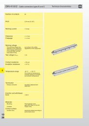
Technical Data<br />
<strong>Power</strong> <strong>Connectors</strong> M 23<br />
Mechanical Data<br />
Housing<br />
Housing surface<br />
Materials and Technical Data<br />
Copper-Zinc alloy<br />
Die Casting<br />
Nickel plated<br />
other surface upon request<br />
Inserts (for contacts) Thermoplastic Polyamid PA 6 (Nylon 6/6), PBT Fire protection class V-0<br />
Contacts<br />
Brass Alloy<br />
Contact surface at point of contact<br />
Nickel and gold plated (0,25 μm Au)<br />
Minimum mating cycles > 1000<br />
Seals / O-Rings<br />
Buna-N standard<br />
optional Viton ® (Viton is a registered trademark of DuPont)<br />
Temperature range<br />
-40° C – 125° C (-40 °F – 257 °F)<br />
Type of contacts<br />
Crimp<br />
Protection<br />
IP 67 / IP 69 K per EN 60 529 (connected), NEMA 4x<br />
Cable diameter range 7 – 17 mm (.28 – .67“)<br />
Electrical Data<br />
Number of positions<br />
Number of contacts<br />
Contact-Ø [mm]<br />
Nominal current 1) [A]<br />
Nominal voltage 2 ) [V~] Degree of Protection 2 3)<br />
Nominal voltage 2 ) [V~] Degree of Protection 3 3)<br />
Test voltage (Breakdown voltage) 4) [V~]<br />
Insulation resistance [mΩ]<br />
Max. contact resistance [mΩ]<br />
5 + PE 4 + 3 + PE<br />
6 4 4<br />
2 1 2<br />
28 8 28<br />
800 300 800<br />
600 300 600<br />
4000 2500 4000<br />
> 10 13 > 10 13<br />
3 3<br />
1), 2), 3), 4)<br />
See Technical Informations page 14<br />
Dimensions and specifications may be changed without prior notice<br />
107
<strong>Power</strong> <strong>Connectors</strong> M 23 / Housing<br />
Straight Connector, Female Thread<br />
Cable-Ø<br />
Part number<br />
78<br />
7 – 12 mm (.24 – .47“).......7.550.500.000<br />
11 – 17 mm (.43 – .67“).....7.550.600.000<br />
85<br />
Ø 26,2<br />
27<br />
24<br />
74,5<br />
M 23 x 1<br />
24<br />
24<br />
81,5<br />
M 23 x 1<br />
Ø 26,2<br />
24<br />
24<br />
Contacts and inserts page 114 • Assembly instructions page 122<br />
Straight Connector, Female Thread, MZ Cable-Ø Part Number<br />
10 – 12 mm (.39 – .47“).....7.559.500.000<br />
11 – 17 mm (.43 – .67“).....7.559.600.000<br />
Contacts and inserts page 114 • Assembly instructions page 122<br />
Straight Connector, Male Thread<br />
Cable-Ø<br />
Part Number<br />
7 – 12 mm (.24 – .47“).......7.560.500.000<br />
11 – 17 mm (.43 – .67“).....7.560.600.000<br />
Contacts and inserts page 114 • Assembly instructions page 122<br />
Straight Connector, Male Thread, MZ<br />
Cable-Ø<br />
Part Number<br />
10 – 12 mm (.39 – .47“).....7.569.500.000<br />
11 – 17 mm (.43 – .67“).....7.569.600.000<br />
27<br />
24<br />
Contacts and inserts page 114 • Assembly instructions page 122<br />
108<br />
Dimensions and specifications may be changed without prior notice
<strong>Power</strong> <strong>Connectors</strong> M 23 / Housing<br />
Cable-Ø Part Number Right Angle Connector, Female Thread, rotating<br />
7 – 12 mm (.24 – .47“).......7.576.500.000<br />
11 – 17 mm (.43 – .67“).....7.576.600.000<br />
24<br />
Contacts and inserts page 114 • Assembly instructions page 124<br />
Cable-Ø Part Number Right Angle Connector, Female Thread, MZ, rotating<br />
9 – 12 mm (.35 – .47“).......7.579.500.000<br />
10 – 14 mm (.39 – .55“).....7.579.600.000<br />
Contacts and inserts page 114 • Assembly instructions page 124<br />
Ø 26,2<br />
Cable-Ø Part Number Right Angle Connector, Male Thread, rotating<br />
7 – 12 mm (.24 – .47“).......7.580.500.000<br />
10 – 14 mm (.39 – .55“).....7.580.600.000<br />
68<br />
22<br />
24<br />
24<br />
62<br />
Contacts and inserts page 114 • Assembly instructions page 124<br />
<strong>M23</strong>x1<br />
Cable-Ø Part Number Right Angle Connector, Male Thread, MZ, rotating<br />
9 – 12 mm (.35 – .47“).......7.589.500.000<br />
10 – 14 mm (.39 – .55“).....7.589.600.000<br />
77,6<br />
22<br />
24<br />
25<br />
62<br />
Contacts and inserts page 114 • Assembly instructions page 124<br />
<strong>M23</strong>x1<br />
Dimensions and specifications may be changed without prior notice<br />
109
<strong>Power</strong> <strong>Connectors</strong> M 23 / Housing<br />
Panel <strong>Connectors</strong>, Male Thread, Front Mounting<br />
Type<br />
Part Number<br />
M 23 x 1<br />
Ø 2,7 – Ø 3,2<br />
4 holes Ø 3,2 mm (.13“).....7.601.000.000<br />
4 holes Ø 2,7 mm (.11“).....7.605.000.000<br />
32,5<br />
25<br />
19,8<br />
Optional:<br />
Flat gasket<br />
Panel hole<br />
Ø 20 + 0,1<br />
Contacts and inserts page 114 • Assembly instructions page 125<br />
Panel Connector with knurled Nut, Front Mounting<br />
Type<br />
Part Number<br />
Ø 26,2<br />
Ø 2,7 – Ø 3,2<br />
4 holes Ø 3,2 mm (.13“).....7.641.000.000<br />
4 holes Ø 2,7 mm (.11“).....7.645.000.000<br />
39,5<br />
25<br />
19,8<br />
Optional:<br />
Flat gasket<br />
Panel hole<br />
Ø 20 + 0,1<br />
Contacts and inserts page 114 • Assembly instructions page 125<br />
110 Dimensions and specifications may be changed without prior notice
<strong>Power</strong> <strong>Connectors</strong> M 23 / Housing<br />
Type<br />
Part Number<br />
Panel Connector, Male Thread, Single Hole Mounted<br />
Front mounting<br />
Thread M 20 x1,5 ..............7.621.000.000<br />
Options:<br />
Flat gasket, jam nut M 20 x 1,5<br />
37,5<br />
M 23 x 1<br />
20,2+ 0,1<br />
19,1+ 0,1<br />
6<br />
26<br />
Panel hole<br />
Contacts and inserts page 114 • Assembly instructions page 126<br />
M 20 x 1,5<br />
20,2 + 0,1<br />
Type<br />
Part Number<br />
Panel Connector, Male Thread, Single Hole Mounted<br />
Front mounting<br />
Thread PG 13,5 .................7.623.000.000<br />
Options:<br />
Flat gasket, jam nut PG 13,5<br />
37,5<br />
M 23 x 1<br />
20,6+ 0,1<br />
19,3+ 0,1<br />
Contacts and inserts page 114 • Assembly instructions page 126<br />
626<br />
PG 13,5<br />
Panel hole<br />
20,6 + 0,1<br />
Type<br />
Part Number<br />
Panel Connector, Male Thread, Single Hole Mounted<br />
Front mounting<br />
Thread M 25x1,5 ...............7.626.000.000<br />
Options:<br />
Flat gasket, jam nut M 25 x 1,5<br />
32,5<br />
M 23 x 1<br />
25+ 0,1<br />
24,1+ 0,1<br />
7<br />
28<br />
Panel hole<br />
M 25 x 1,5<br />
25,2 + 0,1<br />
Contacts and inserts page 114 • Assembly instructions page 126<br />
Type<br />
Part Number<br />
Panel Connector, Male Thread, Single Hole Mounted<br />
Rear mounting<br />
Thread M 25 x 1,5 .............7.651.000.000<br />
Including jam nut M 25 x 1,5<br />
M 25 x 1,5<br />
M 23 x 1<br />
24,1+ 0,1<br />
37,3<br />
33,8<br />
25+ 0,1<br />
29<br />
Panel hole<br />
Contacts and inserts page 114 • Assembly instructions page 126<br />
30<br />
max. 8 mm<br />
25 + 0,1<br />
Dimensions and specifications may be changed without prior notice<br />
111
<strong>Power</strong> <strong>Connectors</strong> M 23 / Housing<br />
Right Angle Panel Connector, Male Thread<br />
Type<br />
Part Number<br />
34,5<br />
29<br />
54,5<br />
M 23 x 1<br />
25<br />
19,8<br />
Ø 2,7<br />
4 holes Ø 2,7 mm (.11“).....7.635.000.000<br />
Options:<br />
Flat gasket<br />
Easy fastening with M 2,5 x 10 mm or #4 x .39“ long screws<br />
Ø 19,8<br />
Panel hole<br />
20 + 0,1<br />
Contacts and inserts page 114 • Assembly instructions page 127<br />
Right Angle Panel Connector, Male Thread, rotating<br />
Type<br />
Part Number<br />
54,5<br />
335° rotating, single hole mounted<br />
Thread M 20 x 1,5 .............7.636.000.000<br />
46<br />
40,5<br />
M 23 x 1<br />
Panel hole<br />
M 20 x 1,5<br />
6<br />
20,2 + 0,1<br />
Contacts and inserts page 114 • Assembly instructions page 127<br />
Right Angle Panel Connector, Male Thread, rotating<br />
Type<br />
Part Number<br />
54,5<br />
335° rotating, single hole mounted<br />
Thread PG 13,5 .................7.637.000.000<br />
46<br />
40,5<br />
M 23 x 1<br />
PG 13,5<br />
6<br />
Panel hole<br />
20,6 + 0,1<br />
Contacts and inserts page 114 • Assembly instructions page 127<br />
Right Angle Panel Connector, Male Thread, rotating<br />
Type<br />
Part Number<br />
54,5<br />
52,5<br />
25<br />
19,8<br />
28 300° rotating, locking screw at flange<br />
Ø 2,7<br />
22,6 Ø 3,2 4 x holes Ø 2,7 mm (.11“) ..7.638.000.000<br />
Flange 25 x 25 mm<br />
43<br />
37,5<br />
M 23 x 1<br />
Panel hole<br />
4 x holes Ø 3,2 mm (.13“) ..7.638.100.000<br />
Flange 28 x 28 mm<br />
20 + 0,1<br />
Contacts and inserts page 114 • Assembly instructions page 127<br />
112 Dimensions and specifications may be changed without prior notice
<strong>Power</strong> <strong>Connectors</strong> M 23 / Housing<br />
Type<br />
Part Number<br />
With anti-vibration O-Ring<br />
4 holes Ø 3,2 mm (.13“).....7.661.000.000<br />
M 23 x 1<br />
Panel Connector, Male Thread, Rear Mounting<br />
Ø 3,2<br />
34,5<br />
32,5<br />
25<br />
20,5<br />
Contacts and inserts page 114 • Assembly instructions page 123<br />
max.<br />
12mm<br />
Panel hole<br />
Ø 23,1 + 0,1<br />
Cable-Ø<br />
Part Number<br />
Single hole mounted, rear mounting, thread M 25 x 1,5<br />
7 – 12 mm (.27 – .47“).......7.653.500.000<br />
11 – 17 mm (.43 – .67“).....7.653.600.000<br />
Including jam nut M 25 x 1,5<br />
Contacts and inserts page 114 • Assembly instructions page 122<br />
71,5<br />
24 30 29<br />
Panel Connector, Male Thread, with Strain Relief<br />
18,8<br />
M 23 x 1<br />
M 25 x 1,5<br />
max.<br />
14 mm<br />
25+ 0,1<br />
Panel hole<br />
Ø 25 + 0,1<br />
24,1+ 0,1<br />
Cable-Ø<br />
Part Number<br />
4 holes Ø 3,2 mm (.13“), front or rear mounting<br />
7 – 12 mm (.27 – .47“).......7.681.500.000<br />
11 – 17 mm (.43 – .67“).....7.681.600.000<br />
46,5<br />
Panel Connector, Female Thread, with Strain Relief<br />
78<br />
28<br />
35<br />
28,4<br />
Ø 26,2<br />
24<br />
Panel hole<br />
Ø 3,2<br />
Contacts and inserts page 114 • Assembly instructions page 122<br />
min. Ø 26,5 + 0,2<br />
Cable-Ø Part Number Panel Connector, Male Thread, with Strain Relief<br />
4 holes Ø 3,2 mm (.13“), front or rear mounting<br />
7 – 12 mm (.27 – .47“).......7.683.500.000<br />
11 – 17 mm (.43 – .67“).....7.683.600.000<br />
71,5<br />
47,5<br />
18,5<br />
35<br />
28,4<br />
M 23 x 1<br />
Contacts and inserts page 114 • Assembly instructions page 122<br />
24<br />
Panel hole<br />
min. Ø 26,5 + 0,2<br />
Ø 3,2<br />
Dimensions and specifications may be changed without prior notice<br />
113
6<br />
6<br />
<strong>Power</strong> <strong>Connectors</strong> M 23 / Inserts / Pinouts<br />
Contact Arrangement, Mating View<br />
Type of Contact<br />
Part Number<br />
7,05<br />
4,85<br />
6 x crimp pins 2 mm .........................................................7.084.951.101<br />
1,85<br />
11,41<br />
7,05<br />
4,85<br />
6 x crimp sockets 2 mm .....................................................7.084.951.102<br />
B<br />
A<br />
1<br />
C<br />
D<br />
3<br />
4<br />
4<br />
C<br />
B<br />
D<br />
3<br />
A<br />
1<br />
6 5,63<br />
6 5,63<br />
11,41<br />
10,52<br />
4,11<br />
10,54<br />
10,52<br />
4,11<br />
2,86<br />
2,86<br />
2,86 2,86<br />
1,85<br />
4 x crimp pins 1 mm<br />
4 x crimp pins 2 mm .........................................................7.084.943.101<br />
4 x crimp sockets 1 mm<br />
4 x crimp sockets 2 mm .....................................................7.084.943.102<br />
10,54<br />
114 Dimensions and specifications may be changed without prior notice
<strong>Power</strong> <strong>Connectors</strong> M 23 / Contacts<br />
Type of Contact Crimp Range Part Number<br />
Contacts<br />
Crimp pin 1 mm, machined 0,25 – 1 mm 2 .....................7.010.941.001<br />
(AWG 24 – 17)<br />
Crimp socket 1 mm, machined 0,25 – 1 mm 2 .....................7.010.941.002<br />
(AWG 24 – 17)<br />
Crimp pin 2 mm, machined 0,75 – 2,5 mm 2 ..................7.010.942.001<br />
(AWG 18 – 14)<br />
Crimp pin 2 mm, machined 2,5 – 4 mm 2 .......................7.010.942.011<br />
(AWG 14 – 12)<br />
Crimp socket 2 mm, machined 0,75 – 2,5 mm 2 ..................7.010.942.002<br />
(AWG 18 – 14)<br />
Crimp socket 2 mm, machined 2,5 – 4 mm 2 .......................7.010.942.012<br />
(AWG 14 – 12)<br />
See page 128 for crimp tool instructions and proper setting<br />
Dimensions and specifications may be changed without prior notice<br />
115
<strong>Power</strong> <strong>Connectors</strong> M 23 / Accessories<br />
Accessories<br />
Type<br />
Part Number<br />
Plastic protective cap<br />
for connectors with male thread .........................................7.000.900.101<br />
for connectors with female thread.......................................7.000.900.102<br />
Brass protective cap<br />
for connectors<br />
with female thread............................................................7.010.900.183<br />
Brass protective cap<br />
for connectors<br />
with male thread ..............................................................7.010.900.102<br />
Brass protective cap<br />
with chain for connectors<br />
with female thread ...................Length 70 mm ....................7.010.9S0.783<br />
..............................................Length 100 mm ..................7.010.9S1.083<br />
Brass protective cap<br />
with chain for connectors<br />
with male thread ......................Length 70 mm ....................7.010.9S0.702<br />
..............................................Length 100 mm ..................7.010.9S1.002<br />
116<br />
Dimensions and specifications may be changed without prior notice
<strong>Power</strong> <strong>Connectors</strong> M 23 / Accessories<br />
Type Part Number Accessories<br />
Crimp tool for manual crimping<br />
of machined crimp contacts.<br />
Works with contacts for power or signal..............................7.000.900.901<br />
Operating instructions on page 118<br />
Adaptor flange<br />
for Straight <strong>Connectors</strong> .....................................................7.010.900.128<br />
Adapter for Conduit Fittings<br />
Snapflex 16.......................7.010.900.204<br />
DN 12 ..............................7.010.900.205<br />
Snapflex 20.......................7.010.900.206<br />
DN 14 ..............................7.010.900.207<br />
Snapflex 25.......................7.010.900.208<br />
DN 17 ..............................7.010.900.209<br />
Type Part Number for HUMMEL Contact<br />
Locator<br />
Locator for Crimp Tool<br />
DMC M22520 with positioner ....7.000.9DM.C06 ...............7.010.941.001, 7.010.942.001, 7.010.942.011<br />
Locator for Crimp Tool<br />
DMC M22520 with positioner ....7.000.9DM.C07 ...............7.010.941.002, 7.010.942.002, 7.010.942.012<br />
Dimensions and specifications may be changed without prior notice<br />
117
0<br />
Crimp Tool for <strong>Power</strong> <strong>Connectors</strong> M 23<br />
Crimp Tool Type Part Number<br />
Crimp tool .......................................................................7.000.900.901<br />
Application<br />
The four indent crimp tool 7.000.900.901 has been developed for optimal crimping of<br />
machined contacts with diameters from 0.14 to 6.0 mm 2 (26 through 10 AWG).<br />
How to Crimp<br />
The reference table indicates the correct locator position to be selected and the crimp<br />
depth to be adjusted for the contact to be crimped. The contact is then inserted through<br />
the access hole of the tool on the opposite side of the locator. The contact is held in place<br />
by closing the handles to the first lock-in position thus preventing the contact from falling<br />
out of the tool and facilitating insertion of the wire into the contact.<br />
The precision ratchet assures consistently accurate crimping every time by forcing the tool<br />
to be closed all the way completing the crimping cycle before the tool can be opened<br />
again.<br />
Exchange of the Locator<br />
The locator can be exchanged by removing the socket head cap screw with a socket wrench.<br />
It can then be disassembled from the hex head screw by turning it counter-clockwise.<br />
Crimp jaws<br />
Scale indicating<br />
0.2 mm increments<br />
3<br />
Adjusting screw<br />
with 0.1 mm increments<br />
Physical stop<br />
Moveable handle<br />
Fixed handle<br />
118<br />
Dimensions and specifications may be changed without prior notice
Crimp Tool for <strong>Power</strong> <strong>Connectors</strong> M 23<br />
Adjustment of Crimp Depth<br />
Crimp depth can be adjusted as follows:<br />
Turn the adjusting screw clockwise for reducing the crimp depth and counter-clockwise<br />
for increasing the crimp depth.<br />
Adjustment Increments:<br />
- 1 space on the adjusting screw = ^ adjustment by 0.01 mm<br />
- 1 full rotation of adjusting screw ^= adjustment by 0.2 mm (indication on the screw<br />
as well as on the rough scale)<br />
- 5 rotations of the adjusting screw =adjustment ^ by 1 mm (indication on the scale)<br />
Crimp Tool<br />
Crimp depth -<br />
Adjusting screw with 0.1 mm increments<br />
Crimp depth +<br />
Scale indicating 0.2 mm increments<br />
Control of Crimp Depth<br />
Crimp tool adjustment is done at the factory, but with frequent use, periodic calibration<br />
is recommended to insure accuracy. This is easily accomplished with a 2.0 mm Ø<br />
wire gauge as follows.<br />
A crimp depth of 2.0 mm is set by means of the adjusting screw (scale mark at „2“,<br />
screw mark at „0“ as shown in the fig. above) and the tool in the closed position.<br />
After insertion of the gauge, there must be just enough space for moving the gauge<br />
inside the entry hole. If the opening is too small or too large to exactly match the<br />
gauge, the deviation (+/-) can be checked by the precision setting of the screw.<br />
Please contact the factory in case the deviation exceeds the tolerances specified by<br />
the contract manufacturer.<br />
Maintenance and Repair<br />
Keep the tool clean and properly stored when not in service. All pivot points need to<br />
be oiled regularly and the spring clips securing the bolts have to always be in place.<br />
For repair please send the tool back to the factory.<br />
Dimensions and specifications may be changed without prior notice<br />
119
Crimp Tool for <strong>Power</strong> <strong>Connectors</strong> M 23<br />
Crimp Tool Setting for HUMMEL Crimp Contacts (Crimp Tool 7.000.900.901)<br />
Part Number Crimp Contact Cross Section mm 2 AWG Crimp Tool Setting mm Locator Setting<br />
7.010.901.001 Crimp pin (signal) 1 mm 0,14 26 0,75 11<br />
0,25 24 0,82 11<br />
0,35 22 0,9 11<br />
0,50 20 1 11<br />
0,75 18 1,08 11<br />
1,0 17 1,2 11<br />
7.010.901.012 Crimp socket (signal) 1 mm 0,14 26 0,75 12<br />
0,25 24 0,8 12<br />
0,35 22 0,87 12<br />
0,50 20 0,97 12<br />
7.010.901.002 Crimp socket (signal) 1 mm 0,50 20 0,95 12<br />
0,75 18 1 12<br />
1,0 17 1,05 12<br />
7.010.901.501 Crimp pin (signal) 1,5 mm 0,14 26 0,75 3<br />
0,25 24 0,82 3<br />
0,35 22 0,9 3<br />
0,50 20 0,96 3<br />
0,75 18 1,03 3<br />
1,0 17 1 3<br />
7.010.901.512 Crimp socket (signal) 1,5 mm 0,14 26 0,75 4<br />
0,25 24 0,8 4<br />
0,35 22 0,87 4<br />
0,50 20 0,97 4<br />
7.010.901.502 Crimp socket (signal) 1,5 mm 0,50 20 0,95 4<br />
0,75 18 1 4<br />
1,0 17 1,05 4<br />
7.010.902.001 Crimp pin (signal) 2 mm 0,75 18 1,3 5<br />
1,0 17 1,4 5<br />
1,5 16 1,55 5<br />
2,5 14 1,75 5<br />
7.010.902.002 Crimp socket (signal) 2 mm 0,75 18 1,3 6<br />
1,0 17 1,4 6<br />
1,5 16 1,55 6<br />
2,5 14 1,75 6<br />
7.010.941.001 Crimp pin (power) 1 mm 0,14 26 0,75 1<br />
0,25 24 0,8 1<br />
0,35 22 0,85 1<br />
0,50 20 1,03 1<br />
0,75 18 1,08 1<br />
1,0 17 1,13 1<br />
120 Dimensions and specifications may be changed without prior notice
Crimp Tool for <strong>Power</strong> <strong>Connectors</strong> M 23<br />
Crimp Tool Setting for HUMMEL Crimp Contacts (Crimp Tool 7.000.900.901)<br />
Part Number Crimp Contact Cross Section mm 2 AWG Crimp Tool Setting mm Locator Setting<br />
7.010.941.002 Crimp socket (power) 1 mm 0,14 26 0,75 2<br />
0,25 24 0,8 2<br />
0,35 22 0,85 2<br />
0,50 20 0,89 2<br />
0,75 18 0,95 2<br />
1 17 1,02 2<br />
7.010.942.001 Crimp pin (power) 2 mm 0,75 18 1,3 7<br />
1 17 1,4 7<br />
1,5 16 1,55 7<br />
2,5 14 1,7 7<br />
7.010.942.011 Crimp pin (power) 2 mm 2,5 14 1,47 7<br />
4 12 1,6 7<br />
7.010.942.002 Crimp socket (power) 2 mm 0,75 18 1,3 8<br />
1 17 1,4 8<br />
1,5 16 1,55 8<br />
2,5 14 1,7 8<br />
7.010.942.012 Crimp socket (power) 2 mm 2,5 14 1,47 8<br />
4 12 1,6 8<br />
These values are only guidelines and actual conductor cross sections depend on manufacturer tolerances.<br />
Please see assembly instructions on page 128<br />
Dimensions and specifications may be changed without prior notice<br />
121
<strong>Power</strong> <strong>Connectors</strong> M 23 / Assembly Instructions<br />
Straight Connector, Female Thread<br />
max. 37mm<br />
x<br />
!<br />
x<br />
Contact 1 mm = 4 mm<br />
Contact 2 mm = 7 mm<br />
Crimp<br />
click click<br />
27 24<br />
122<br />
Dimensions and specifications may be changed without prior notice
<strong>Power</strong> <strong>Connectors</strong> M 23 / Assembly Instructions<br />
Panel Connector, Male Thread<br />
1.<br />
x<br />
!<br />
x<br />
Contact 1 mm = 4 mm<br />
Contact 2 mm = 7 mm<br />
2.<br />
Crimp click click<br />
3.<br />
click<br />
4.<br />
Dimensions and specifications may be changed without prior notice<br />
123
<strong>Power</strong> <strong>Connectors</strong> M 23 / Assembly Instructions<br />
Right Angle Connector, rotating<br />
65mm<br />
click click<br />
x<br />
!<br />
x<br />
Contact 1 mm = 4 mm<br />
Contact 2 mm = 7 mm<br />
27<br />
Crimp<br />
27 25<br />
124<br />
Dimensions and specifications may be changed without prior notice
<strong>Power</strong> <strong>Connectors</strong> M 23 / Assembly Instructions<br />
Panel Connector, Female Thread<br />
1.<br />
x<br />
!<br />
x<br />
Contact 1 mm = 4 mm<br />
Contact 2 mm = 7 mm<br />
2.<br />
Crimp click click<br />
3.<br />
click<br />
4.<br />
Dimensions and specifications may be changed without prior notice<br />
125
<strong>Power</strong> <strong>Connectors</strong> M 23 / Assembly Instructions<br />
Panel Connector, Male Thread, Single Hole Mounted<br />
1.<br />
x<br />
!<br />
x<br />
Contact 1 mm = 4 mm<br />
Contact 2 mm = 7 mm<br />
2.<br />
Crimp<br />
click click<br />
3.<br />
click<br />
4.<br />
126<br />
Dimensions and specifications may be changed without prior notice
x<br />
<strong>Power</strong> <strong>Connectors</strong> M 23 / Assembly Instructions<br />
Right Angle Panel Connector<br />
1. 4.<br />
!<br />
x<br />
Contact 1 mm = 4 mm<br />
Contact 2 mm = 7 mm<br />
2.<br />
Crimp<br />
5.<br />
3.<br />
click click<br />
6.<br />
2mm<br />
1,5mm<br />
Dimensions and specifications may be changed without prior notice<br />
127
Crimping, Assembly and Disassembly<br />
Crimping, Assembly and Disasembly<br />
Crimping<br />
- For 1 mm contacts strip wire ends 4 mm (.16“) max.,<br />
for 2 mm contacts strip wire ends 7 mm (.28“) max.<br />
- Dial appropriate setting of crimping tool (page 120 / 121)<br />
- Push crimp contact into opening of crimping tool<br />
- Insert stripped wire into the funnel shaped end of the crimp contact<br />
- Squeeze handles of crimping tool together, connecting contact to wire<br />
Assembly<br />
- Remove crimped assembly and pull on wire to test connection<br />
- Push into desired position of insert<br />
Note: For 8-pole inserts (4 + 3 + PE) it is recommended to assemble the<br />
large contacts first.<br />
Disassembly of Contacts from Insert<br />
A small screw driver is required.<br />
- Using the screw driver, push the white clip ring out of the insert<br />
- Pull the contacts out of the insert<br />
- Replace the white clip ring<br />
- Re-insert the contacts<br />
Disassembly of Insert from Housing<br />
A small screw driver is required. Push locking tongue, located above the PE-contact,<br />
down. By simultaneously pushing on the front side of the insert, it can be disassembled<br />
from the housing.<br />
Shielding<br />
- Assemble strain relief insert with insert<br />
- Fold stranding of the shield back over the first O-Ring of the strain relief insert<br />
- Cut back the overextending braid<br />
!<br />
The stranding of the shield is not allowed to touch the second O-Ring.<br />
Otherwise the assembly may not be proof.<br />
128<br />
Dimensions and specifications may be changed without prior notice