Download Harting D-Sub Mixed Connectors PDF - Northern ...
Download Harting D-Sub Mixed Connectors PDF - Northern ...
Download Harting D-Sub Mixed Connectors PDF - Northern ...
- No tags were found...

You also want an ePaper? Increase the reach of your titles
YUMPU automatically turns print PDFs into web optimized ePapers that Google loves.
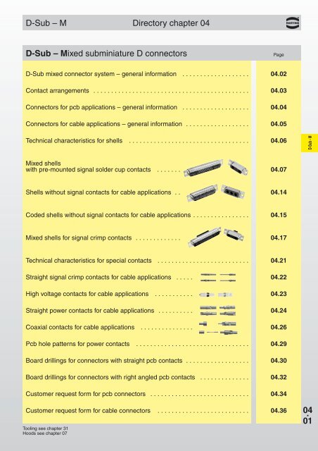
D-<strong>Sub</strong> – MDirectory chapter 04D-<strong>Sub</strong> – <strong>Mixed</strong> subminiature D connectorsPageD-<strong>Sub</strong> mixed connector system – general information . . . . . . . . . . . . . . . . . . . 04.02Contact arrangements . . . . . . . . . . . . . . . . . . . . . . . . . . . . . . . . . . . . . . . . . . . . 04.03<strong>Connectors</strong> for pcb applications – general information . . . . . . . . . . . . . . . . . . . 04.04<strong>Connectors</strong> for cable applications – general information . . . . . . . . . . . . . . . . . . 04.05Technical characteristics for shells . . . . . . . . . . . . . . . . . . . . . . . . . . . . . . . . . . 04.06D-<strong>Sub</strong> - M<strong>Mixed</strong> shellswith pre-mounted signal solder cup contacts . . . . . . . 04.07Shells without signal contacts for cable applications . . 04.14Coded shells without signal contacts for cable applications . . . . . . . . . . . . . . . . 04.15<strong>Mixed</strong> shells for signal crimp contacts . . . . . . . . . . . . . 04.17Technical characteristics for special contacts . . . . . . . . . . . . . . . . . . . . . . . . . . 04.21Straight signal crimp contacts for cable applications . . . . . 04.22High voltage contacts for cable applications . . . . . . . . . . . 04.23Straight power contacts for cable applications . . . . . . . . . . 04.24Coaxial contacts for cable applications . . . . . . . . . . . . . . . 04.26Pcb hole patterns for power contacts . . . . . . . . . . . . . . . . . . . . . . . . . . . . . . . . 04.29Board drillings for connectors with straight pcb contacts . . . . . . . . . . . . . . . . . . 04.30Board drillings for connectors with right angled pcb contacts . . . . . . . . . . . . . . 04.32Customer request form for pcb connectors . . . . . . . . . . . . . . . . . . . . . . . . . . . . 04.34Customer request form for cable connectors . . . . . . . . . . . . . . . . . . . . . . . . . . 04.36Tooling see chapter 31Hoods see chapter 0704 .01
D-<strong>Sub</strong> mixed connector systemGeneral informationHARTINGs’ mixed D-<strong>Sub</strong> range brings theadvantage of an industry standard I/O interconnectproduct with the possibility to customisefor any application.The range is designed around the standardD-<strong>Sub</strong> shell sizes with the possibility to have ablend of contacts such as signals with coaxial,power or high voltage contacts. Due to itsconstruction, the product is fully shielded andhelps reducing the EMI/RFI leakage.D-<strong>Sub</strong> - MAll contacts are machined with two differentplatings.When hot plug-in is required, first mate lastbreak contacts can also be supplied.For connectors to be fitted on a board with SMTcomponents, they can be supplied in an SMC(PiHIR) version which is assembled in the reflowsolder process, thus reducing assembly cost.In addition, a complete range of accessories suchas clinch nut, spacers, board locks, female screwlock, etc. … meeting the requirements of virtuallyany application, including a blind mate feature,makes this product range very attractive thanks toits versatility, reliability and cost effectiveness.04 .02
D-<strong>Sub</strong>Contact arrangementsThe table shows the standard range supported byHARTING. Two versions are special since theyallow to mix in the same shell male and femalecontacts: 2W2C and 3W3C. The purpose of theseversions is to have a 100 % mating proof feature(the insulator shape prevents a 180° reversedmating).The structure of the connectors’ identification isso that the left side digits give the total number ofcontacts and the right side digits the number ofspecial contacts which can be either power,coaxial or high voltage style.Example: 13W3 stands for 13 contacts in totalwith 10 signal contacts and 3 special contacts.7W78W813W621WA425W3D-<strong>Sub</strong> - M27W224W736W42W2C5W13W33W3C7W211W15W59W413W317W221W1Note:for any other layout please consult your HARTING representative.04 .03
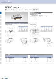
D-<strong>Sub</strong><strong>Connectors</strong> for pcb applications – general informationThe range of pcb connectors available at HARTING is summarised in the table under. For each of the basicconnector versions, the available contact styles are documented with termination process, pitch, plating, ratingfor power contacts and impedance for coaxial contact etc..., as well as the accessory configuration.Pcb connectors are delivered fully loaded thus providing a very good positioning of the contacts in theircavities for an easy and safe insertion of the pins in the pcb holes particularly crucial in the right angled versions.Due to the numerous possibilities offered with the pcb connectors, suggested method is to contact your localHARTING representative to determine the part number to order; see customer request form on pages 04.34 and04.35.StraightRight angledD-<strong>Sub</strong> - MInsulator body● Standard● SMC: Solder Reflow Compatible● Standard● SMC: Solder Reflow CompatibleSignal contactsSolder termination● Pitch: 2.84 mm● Plating: 0.76 µm Au over Ni● Pcb thickness from 1.6 to 3.2 mmSolder termination● Pitch: 2.54 mm● Plating: 0.76 µm Au over Ni● Pcb thickness from 1.6 to 3.2 mmPower contactsSolder termination● Rating: 20, 30, 40 A● Plating: 0.76 µm Au over NiPress fit termination● Rating: 30 A● Plating: 0.76 µm Au over NiSolder termination● Rating: 20, 30, 40 A● Plating: 0.76 µm Au over NiCoaxial contactsSolder termination● 50 or 75 Ω● Plating:1.3 µm Au over Ni inner conductor0.76 µm Au over Ni outer ringSolder termination● 50 or 75 Ω● Plating:1.3 µm Au over Ni inner conductor0.76 µm Au over Ni outer ringThrough holeMetal bracket withboard lock andthrough holeNut:M3 or UNC 4-40Metal bracket withboard lock andclinch nut M3or UNC 4-40AccessoriesSpacer:M3 or UNC 4-40Metal bracketwith board lockand female screwlock UNC 4-40Spacer(M3 or UNC 4-40)with board lock04 .04Spacer+ board lock+ female screw lockM3 or UNC 4-40
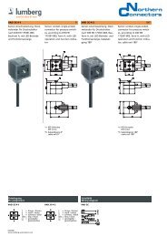
D-<strong>Sub</strong><strong>Connectors</strong> for cable applications – general informationTwo termination processes are available: crimp or solderShellSignal contactsCrimp termination● For wire gauge: AWG 20-24 or 26-28● Plating: 0.76 µm or 0.2 µm Au over NiPre-mounted solder cup contacts● Plating: 0.76 µm or 0.1 µm Au over NiD-<strong>Sub</strong> - MPower contactsCrimp● Rating: 20, 30, 40 A● Plating: 0.76 µm or 0.2 µm Au over NiSolder cup● Rating: 20, 30, 40 A● Plating: 0.76 µm or 0.2 µm Au over NiCrimp● Rating: 20, 30, 40 A● Plating: 0.76 µm or 0.2 µm Au over NiSolder cup● Rating: 20, 30, 40 A● Plating: 0.76 µm or 0.2 µm Au over NiCoaxialcontacts 1)Solder/crimp termination● 50 or 75 Ω● Plating:1.3 µm or 0.2 µm Au over Ni innerconductor0.76 µm or 0.2 µm Au over Ni outer ring● Cables: RG 178, 179 …Crimp/crimp termination● 50 or 75 Ω● Plating:1.3 µm or 0.2 µm Au over Ni innerconductor0.76 µm or 0.2 µm Au over Ni outer ring● Cables: RG 178, 179 …Solder/crimp termination● 50 or 75 Ω● Plating:1.3 µm or 0.2 µm Au over Ni innerconductor0.76 µm or 0.2 µm Au over Ni outer ring● Cables: RG 178, 179 …Crimp/crimp termination● 50 or 75 Ω● Plating:1.3 µm or 0.2 µm Au over Ni innerconductor0.76 µm or 0.2 µm Au over Ni outer ring● Cables: RG 178, 179 …High voltagecontactsSolder termination● Plating:1.3 µm Au over Ni terminatingand mating sideSolder termination● Plating:1.3 µm Au over Ni terminatingand mating side1) Coaxial contacts are provided in two versions:● Inner conductor soldered and outer part crimped (solder/crimp termination)● Both inner and outer part crimped (crimp/crimp termination); this version is recommended for medium orlarge size volume since crimping is faster than soldering.04 .05
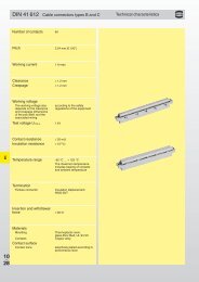
D-<strong>Sub</strong> mixed connectorsTechnical characteristics for shellsNumber of contacts 2, 3, 5, 7, 8, 9, 11, 13, 17,21, 24, 25, 27, 36Approvals DIN 41 652, part 1MIL-C 24 308D-<strong>Sub</strong> - MWorking current5 A for signal contactsTemperature rangeThe higher temperature limitincludes the ambientand heating effect of thecontacts under load-55 O C … + 125 O CMaterialsMouldingsMetal shellThermoplastic resin, glassfibrefilled (Polyester)UL 94-V0color: green for standardblack for crimpPlated steel04 .06Technical characteristics for special contacts see page 04.21
D-<strong>Sub</strong>DIN 41 652 T1Number of contacts7--27<strong>Mixed</strong> shells with pre-mounted signal solder cup contactsNo. ofIdentification contacts 1) Part No.male connectorsfemale connectorsPerformance level 3 S4 2) Performance level 3S4 2)7W2 09 69 211 7072 09 69 211 5072 09 69 201 7072 09 69 201 5072D-<strong>Sub</strong> - M17W2 09 69 311 7172 09 69 311 5172 09 69 301 7172 09 69 301 517221WA4 09 69 411 7214 09 69 411 5214 09 69 401 7214 09 69 401 521427W2 09 69 411 7272 09 69 411 5272 09 69 401 7272 09 69 401 5272Male connectorsSolder cup termination for AWG 20 (0.5 mm²)a b c d e7W2 24.6 39.1 27.5 33.30 25.217W2 38.3 53.0 41.3 47.04 38.921WA4 54.8 69.3 57.7 63.50 55.327W2 54.9 69.3 57.7 63.50 55.3Female connectorsSolder cup termination for AWG 20 (0.5 mm²)1)Explanations see page 04.03 Board drillings see pages 04.29 ff2)S4: ≥ 0.76 µm Au Order special contacts separately. See pages 04.21 ffDimensions in mm04 .07
D-<strong>Sub</strong>DIN 41 652 T1Number of contacts9--25<strong>Mixed</strong> shells with pre-mounted signal solder cup contactsNo. ofIdentification contacts 1) Part No.male connectorsfemale connectorsPerformance level 3 S4 2) Performance level 3S4 2)D-<strong>Sub</strong> - M9W4 09 69 311 7094 09 69 311 5094 09 69 301 7094 09 69 301 509413W3 09 69 311 7133 09 69 311 5133 09 69 301 7133 09 69 301 513325W3 09 69 411 7253 09 69 411 5253 09 69 401 7253 09 69 401 5253Male connectors9W4Solder cup termination for AWG 20 (0.5 mm²)13W3, 25W3Solder cup termination for AWG 20 (0.5 mm²)b c d e13W3 53.0 41.3 47.04 38.9025W3 69.3 57.7 63.50 49.8404 .081)Explanations see page 04.032)S4: ≥ 0.76 µm AuBoard drillings see pages 04.29 ffDrawings for female connectors see page 04.09Order special contacts separately. See pages 04.21 ffDimensions in mm
D-<strong>Sub</strong>DIN 41 652 T1Number of contacts9--25<strong>Mixed</strong> shells with pre-mounted signal solder cup contactsIdentification Drawing Dimensions in mmFemale connectors9W4D-<strong>Sub</strong> - MSolder cup termination for AWG 20 (0.5 mm²)13W3, 25W3Solder cup termination for AWG 20 (0.5 mm²)a b c d13W3 38.3 53.0 41.3 47.0425W3 54.9 69.3 57.7 63.50Board drillings see pages 04.29 ff04 .09
D-<strong>Sub</strong>DIN 41 652 T1Number of contacts5--21<strong>Mixed</strong> shells with pre-mounted signal solder cup contactsNo. ofIdentification contacts 1) Part No.male connectorsfemale connectorsPerformance level 3 S4 2) Performance level 3S4 2)D-<strong>Sub</strong> - M5W1 09 69 111 7051 09 69 111 5051 09 69 101 7051 09 69 101 505111W1 09 69 211 7111 09 69 211 5111 09 69 201 7111 09 69 201 511121W1 09 69 311 7211 09 69 311 5211 09 69 301 7211 09 69 301 5211Male connectorsSolder cup termination for AWG 20 (0.5 mm²)Female connectorsSolder cup termination for AWG 20 (0.5 mm²)04 .10a b c d e5W1 16.4 30.8 19.3 25.00 16.911W1 24.7 39.1 27.5 33.30 25.221W1 38.5 53.0 41.3 47.04 38.91)Explanations see page 04.03 Order special contacts separately. See pages 04.21 ff2)S4: ≥ 0.76 µm AuDimensions in mm
D-<strong>Sub</strong>DIN 41 652 T1Number of contacts13<strong>Mixed</strong> shells with pre-mounted signal solder cup contactsNo. ofIdentification contacts 1) Part No.male connectorsfemale connectorsPerformance level 3 S4 2) Performance level 3S4 2)13W6 09 69 411 7136 09 69 411 5136 09 69 401 7136 09 69 401 5136D-<strong>Sub</strong> - MMale connectorsSolder cup terminationfor AWG 20 (0.5 mm²)Female connectorsSolder cup terminationfor AWG 20 (0.5 mm²)1)Explanations see page 04.032)S4: ≥ 0.76 µm AuOrder special contacts separately. See pages 04.21 ffDimensions in mm04 .11
D-<strong>Sub</strong>DIN 41 652 T1Number of contacts24<strong>Mixed</strong> shells with pre-mounted signal solder cup contactsNo. ofIdentification contacts 1) Part No.male connectorsfemale connectorsPerformance level 3 S4 2) Performance level 3S4 2)D-<strong>Sub</strong> - M24W7 09 69 511 7247 09 69 511 5247 09 69 501 7247 09 69 501 5247Male connectorsSolder cup terminationfor AWG 20 (0.5 mm²)Female connectorsSolder cup terminationfor AWG 20 (0.5 mm²)04 .121)Explanations see page 04.032)S4: ≥ 0.76 µm AuOrder special contacts separately. See pages 04.21 ffDimensions in mm
D-<strong>Sub</strong>DIN 41 652 T1Number of contacts36<strong>Mixed</strong> shells with pre-mounted signal solder cup contactsNo. ofIdentification contacts 1) Part No.male connectorsfemale connectorsPerformance level 3 S4 2) Performance level 3S4 2)36W4 09 69 511 7364 09 69 511 5364 09 69 501 7364 09 69 501 5364D-<strong>Sub</strong> - MMale connectorsSolder cup terminationfor AWG 20 (0.5 mm²)Female connectorsSolder cup terminationfor AWG 20 (0.5 mm²)1)Explanations see page 04.032)S4: ≥ 0.76 µm AuOrder special contacts separately. See pages 04.21 ffDimensions in mm04 .13
D-<strong>Sub</strong>DIN 41 652 T1Number of contacts3--8Shells without signal contacts for cable applicationsNo. ofIdentification contacts 1) Part No.male connectorsfemale connectorsD-<strong>Sub</strong> - M3W3 09 69 210 0033 09 69 200 00335W5 09 69 310 0055 09 69 300 00557W7 09 69 410 0077 09 69 400 00778W8 09 69 410 0088 09 69 400 0088Male connectorsa b c d e3W3 25.2 39.1 27.5 33.30 24.65W5 38.9 53.0 41.3 47.04 38.37W7 55.3 69.3 57.7 63.50 54.98W8 55.3 69.3 57.7 63.50 54.8Female connectors04 .141)Explanations see page 04.03Board drillings see pages 04.29 ffOrder special contacts separately. See pages 04.21 ffDimensions in mm
D-<strong>Sub</strong>DIN 41 652 T1Number of contacts2Coded shells without signal contacts for cable applicationsNo. ofIdentification contacts 1) Part No.male connectorfemale connectorMale connectors2W2C 09 69 110 0022 09 69 100 0022D-<strong>Sub</strong> - MFemale connectors1)Explanations see page 04.03Board drillings see pages 04.29 ffOrder special contacts separately. See pages 04.21 ffDimensions in mm04 .15
D-<strong>Sub</strong>DIN 41 652 T1Number of contacts3Coded shells without signal contacts for cable applicationsNo. ofIdentification contacts 1) Part No.male connectorfemale connectorD-<strong>Sub</strong> - MMale connectors3W3C 09 69 210 0633 09 69 200 0633detail:polarization featureFemale connectorsdetail:polarization feature04 .161)Explanations see page 04.03Board drillings see pages 04.29 ffOrder special contacts separately. See pages 04.21 ffDimensions in mm
D-<strong>Sub</strong>DIN 41 652 T1Number of contacts7--21<strong>Mixed</strong> shells for signal crimp contactsNo. ofIdentification contacts 1) Part No.male connectorsfemale connectors7W2 09 69 212 0072 09 69 202 0072D-<strong>Sub</strong> - M17W2 09 69 312 0172 09 69 302 017221WA4 09 69 412 0214 09 69 402 0214Male connectorsa b c d e7W2 25.2 39.1 27.5 33.30 24.717W2 38.9 53.0 41.3 47.04 38.521WA4 55.3 69.3 57.7 63.50 54.9Female connectors1)Explanations see page 04.03Board drillings see pages 04.29 ffOrder special contacts separately. See pages 04.21 ffDimensions in mm04 .17
D-<strong>Sub</strong>DIN 41 652 T1Number of contacts13<strong>Mixed</strong> shells for signal crimp contactsNo. ofIdentification contacts 1) Part No.male connectorfemale connectorD-<strong>Sub</strong> - MMale connectors13W3 09 69 312 0133 09 69 302 0133Female connectors04 .181)Explanations see page 04.03Board drillings see pages 04.29 ffOrder special contacts separately. See pages 04.21 ffDimensions in mm
D-<strong>Sub</strong>DIN 41 652 T1Number of contacts21<strong>Mixed</strong> shells for signal crimp contactsNo. ofIdentification contacts 1) Part No.male connectorfemale connectorMale connectors21W1 09 69 312 0211 09 69 302 0211D-<strong>Sub</strong> - MFemale connectors1)Explanations see page 04.03Order special contacts separately. See pages 04.21 ffDimensions in mm04 .19
NotesD-<strong>Sub</strong> - M04 .20
D-<strong>Sub</strong> mixed connectorsTechnical characteristics for special contactsSignal contacts Coaxial contacts Power contacts High voltage contactssee page 04.22 see pages 04.26 – 04.28 see pages 04.24 + 04.25 see page 04.23Working current 5 A 2 A 20 A, 30 A or 40 A 2 A DCTest voltage U r.m.s. – 750 V / 50 Hz – 4 kV / 50 HzOperating voltage – – – ≤ 3 kVContact resistance – ≤ 2.7 mΩ ≤ 1 mΩ ≤ 3 mΩ(inner and outer(outerconductor)conductor)Impedance – 50 / 75 Ω – –D-<strong>Sub</strong> - MFrequency range – 0 - 2 GHz – –Temperature range – -55 °C … + 135 °C -55 °C … + 155 °C -55 °C … + 125 °CMating cycleshigh performance level ≥ 500 ≥ 500 ≥ 500 –standard performance ≥ 200 ≥ 200 ≥ 200 ≥ 500levelMating force ≤ 3.4 N ≤ 7 N/mated pair ≤ 7 N/mated pair ≤ 5 NUnmating force ≥ 0.2 N ≤ 7 N/mated pair appr. 5 N appr. 2.5 NMaterialsContacts Copper alloy Copper alloy Copper alloy Copper alloyPlating*Mating side / 0.76 µm Au / 0.76 µm Au 0.76 µm Au / 0.2 µm Au 1.3 µm Au / 1.3 µm Auterminating side or 0.2 µm Au / 0.2 µm Au or 0.2 µm Au / 5 µm SnInner conductor – 1.3 µm Au / 1.3 µm Au – –mating side /or 0.2 µm Au / 0.2 µm Auterminating sideOuter conductor – 0.76 µm Au / 0.2 µm Au – –mating side /or 0.2 µm Au / 5 µm Snterminating sideRetaining clip – Copper alloy Copper alloy PIInsulator – PBFE/PBTP/PI – PTFETechnical characteristics for shells see page 04.06* High performance or standard performance level04 .21
D-<strong>Sub</strong>DIN 41 652 T1Straight signal crimp contacts for cable applicationsWire gaugeIdentification (mm²) Part No.Performance level3 S4 1)D-<strong>Sub</strong> - MMale contact0.09 - 0.14AWG28 - 2609 69 282 7311 09 69 282 53110.25 - 0.56AWG24 - 2009 69 282 7310 09 69 282 5310Female contact0.09 - 0.14AWG28 - 2609 69 182 7311 09 69 182 53110.25 - 0.56AWG24 - 2009 69 182 7310 09 69 182 5310Male contactFemale contact04 .221)S4: ≥ 0.76 µm AuTooling see chapter 31Dimensions in mm
D-<strong>Sub</strong>DIN 41 652 T1High voltage contacts for cable applicationsWire gaugeIdentification (mm²) Part No.Male contactsPlating: 1.3 µm Au 1)Female contactsPlating: 1.3 µm Au 1)Straight versionsD-<strong>Sub</strong> - M0.25 - 0.56AWG24 - 2009 69 281 255009 69 181 2550Right angled versions0.25 - 0.56AWG24 - 2009 69 681 255009 69 581 2550Male contactsFemale contactsStraight versionsstripping dimensionsRight angled versionsstripping dimensions1)for mating and terminating sideDimensions in mm04 .23
D-<strong>Sub</strong>DIN 41 652 T1Straight power contacts for cable applicationsRatingIdentification (A) Part No.Performance levelsþPerformance level3 S4 1)D-<strong>Sub</strong> - MSolder versionMale contacts10 09 69 281 7420 09 69 281 542020 09 69 281 7421 09 69 281 542130 09 69 281 7422 09 69 281 542240 09 69 281 7423 09 69 281 5423Female contacts10 09 69 181 7420 09 69 181 542020 09 69 181 7421 09 69 181 542130 09 69 181 7422 09 69 181 542240 09 69 181 7423 09 69 181 5423Crimp version 2)Male contacts10 09 69 282 7420 09 69 282 542020 09 69 282 7421 09 69 282 542130 09 69 282 7422 09 69 282 542240 09 69 282 7423 09 69 282 5423Female contacts10 09 69 182 7420 09 69 182 542020 09 69 182 7421 09 69 182 542130 09 69 182 7422 09 69 182 542240 09 69 182 7423 09 69 182 542304 .241)S4: ≥ 0.76 µm Au2)Tooling see chapter 31Dimensions see page 04.25
D-<strong>Sub</strong>DIN 41 652 T1Straight power contacts for cable applicationsIdentification Drawing Dimensions in mmMale contactssoldercrimpD-<strong>Sub</strong> - Mstripping dimensions7,5Rating (A) ø a -0.1 ø b ±0.0510 1.8 2.5420 2.7 3.6330 3.5 4.4040 4.8 5.50Rating (A) ø x -0.1 ø y ±0.05 AWG10 1.7 2.6 16 - 2020 2.6 3.6 12 - 1430 3.7 4.7 10 - 1240 4.6 5.8 8 - 10Female contactssoldercrimpstripping dimensions7,504 .25
D-<strong>Sub</strong>DIN 41 652 T1Coaxial contacts for cable applicationsImpedanceIdentification (Ω) Part No.Straight male contactsStraight female contactsD-<strong>Sub</strong> - MSolder / crimp contactfor cablesRG 174 U, 188 AU, 316 UPerformance level3Performance levelS4 1) 3S4 1)50 09 69 281 7140 09 69 281 5140 09 69 181 7140 09 69 181 5140for cablesRG 178 BU, 196 AU, 404 Ufor cablesRG 58 CU, 141 AU50 09 69 281 7141 09 69 281 5141 09 69 181 7141 09 69 181 514150 09 69 281 7143 09 69 281 5143 09 69 181 7143 09 69 181 5143for cablesRG 179 BU, 187 AU75 09 69 281 7230 09 69 281 5230 09 69 181 7230 09 69 181 5230Crimp / crimp contactfor cablesRG 174 U, 188 AU, 316 Ufor cablesRG 179 BU, 187 AUfor cablesRG 5950 09 69 282 7140 09 69 282 5140 09 69 182 7140 09 69 182 514075 09 69 282 7230 09 69 282 5230 09 69 182 7230 09 69 182 523075 09 69 282 7232 09 69 282 5232 09 69 182 7232 09 69 182 5232Harnessing dimensions (mm)Part No. Ø A Ø B Ø C Ø D E F G04 .261)S4: ≥ 0.76 µm AuDimensions see pages 04.27 and 04.28Tooling see chapter 3109 69 181 x14009 69 281 x14009 69 181 x14109 69 281 x14109 69 181 x14309 69 281 x14309 69 181 x23009 69 281 x23009 69 182 x14009 69 282 x14009 69 182 x23009 69 282 x23009 69 182 x23209 69 282 x2320.85 1.9 2.3 3.2 9.5 5.0 3.00.85 1.2 1.4 2.3 9.5 5.0 3.01.00 3.0 4.4 5.2 9.5 5.0 3.00.50 1.9 2.3 3.2 9.5 5.0 3.00.60 1.9 2.4 3.2 9.0 5.0 3.00.60 1.9 2.4 3.2 9.0 5.0 3.00.95 3.8 5.1 6.2 9.0 4.3 3.7
D-<strong>Sub</strong>DIN 41 652 T1Coaxial contacts for cable applicationsIdentification Drawing Dimensions in mmMale contactsPart No. ø a ø b ø c ø d09 69 281 x140 0.85 1.9 2.6 3.209 69 281 x141 0.85 1.2 1.7 2.309 69 281 x230 0.50 1.9 2.6 3.2D-<strong>Sub</strong> - MPoints of plating thickness measurementPart No. ø a ø b ø c ø d09 69 281 x143 1.0 3.0 4.4 5.2Part No. ø a ø b ø c ø d09 69 282 x140 0.6 1.9 2.6 3.209 69 282 x230 0.6 1.9 2.6 3.2Part No. ø a ø b ø c ø d09 69 282 x232 0.95 3.8 5.1 6.204 .27
D-<strong>Sub</strong>DIN 41 652 T1Coaxial contacts for cable applicationsIdentification Drawing Dimensions in mmFemale contactsD-<strong>Sub</strong> - MPart No. ø a ø b ø c ø d09 69 181 x140 0.85 1.9 2.6 3.209 69 181 x141 0.85 1.2 1.7 2.309 69 181 x230 0.50 1.9 2.6 3.2Points of plating thickness measurementPart No. ø a ø b ø c ø d09 69 181 x143 1.0 3.0 4.4 5.2Part No. ø a ø b ø c ø d09 69 182 x140 0.6 1.9 2.6 3.209 69 182 x230 0.6 1.9 2.6 3.2Part No. ø a ø b ø c ø d09 69 182 x232 0.95 3.8 5.1 6.204 .28
D-<strong>Sub</strong>Pcb hole patterns for power contactsIn the next pages, the pcb hole pattern is given for the power and the coaxial contact per connector layout.In the case of the power contact, the drilling hole dimension is not mentioned; the table here under providesrelevant information according to the current rating of the contact and its version.Power contact diameter and pcb related drilling diameterD-<strong>Sub</strong> - MStraight connectorsRight angled connectorsRating Pin Ø (mm) Pcb drilling Ø (mm) Pin Ø (mm) Pcb drilling Ø (mm)20 A 2.6 2.9 2.85 3.1530 A – – 3.20 3.5040 A 3.75 4.0 3.75 4.0504 .29
D-<strong>Sub</strong>DIN 41 652 T1Board drillings for connectors with straight pcb contactsIdentification Drawing Dimensions in mmMale connector* Power contact Coaxial contactD-<strong>Sub</strong> - M3W3 / 3W3C5W57W28W804 .30* When using a female connector with straight pcb contacts the board drilling pattern must be mirrored in the Y axis.
D-<strong>Sub</strong>DIN 41 652 T1Board drillings for connectors with straight pcb contactsIdentification Drawing Dimensions in mmMale connector* Power contact Coaxial contact9W4D-<strong>Sub</strong> - M13W317W221WA4* When using a female connector with straight pcb contacts the board drilling pattern must be mirrored in the Y axis.04 .31
D-<strong>Sub</strong>DIN 41 652 T1Board drillings for connectors with right angled pcb contactsIdentification Drawing Dimensions in mmMale connector* Power contact Coaxial contactD-<strong>Sub</strong> - M3W3 / 3W3C5W57W28W804 .32* When using a female connector with right angled pcb contacts the board drilling pattern must be mirrored in the Y axis.
D-<strong>Sub</strong>DIN 41 652 T1Board drillings for connectors with right angled pcb contactsIdentification Drawing Dimensions in mmMale connector* Power contact Coaxial contact9W4D-<strong>Sub</strong> - M13W317W221WA4* When using a female connector with right angled pcb contacts the board drilling pattern must be mirrored in the Y axis.04 .33
D-<strong>Sub</strong>HARTING customer request form for pcb connectors1 Connector gender and type■ Male■ Female■ Straight■ Right angled2 Contact arrangementD-<strong>Sub</strong> - MStandard ■ 3W3 ■ 8W8 ■ 21WA4 ■ Other configuration■ 5W5 ■ 13W3 ■ 24W7 ______________________________________________■ 7W2 ■ 17W2 ■ 36W4 ______________________________________________Special configurations ■ 2W2C ■ 3W3C(mixed contact genders)2.1 Any signal contacts? ■ Yes (fill in questions below) ■ No (go directly to item 2.2)■ Right angled 2.54 mm pitch■ Other pitch: ________________________________________________________________________________________________________2.2 Any power contacts? ■ Yes (fill in questions below) ■ No (go directly to item 2.3)Current rating ■ 10 A ■ 30 A■ 20 A ■ 40 ATermination typePerformance level[mating side / termination side]■ Solder pin for pcb■ Press in for pcb (30A)■ S4 [0.76 µm Au / 0.2 µm Au]■ PL 3 [0.2 µm Au / 5.0 µm Sn]2.3 Any coaxial contacts? ■ Yes (fill in questions below) ■ No (go directly to item 3)04 .34ImpedancePerformance level[mating side inner / outer conductor]■ 50 Ω■ 75 Ω■ S4 [1.3 µm Au / 0.76 µm Au]■ PL 3 [0.2 µm Au / 0.2 µm Au]
D-<strong>Sub</strong>HARTING customer request form for pcb connectors3 Pcb mounting accessories (select appropriate fixing accessories)3.1 Right angled version ■ Through hole■ Nut 4-40 UNC■ Nut M3■ Metal bracket■ Snap clipScrew lock■ fixed■ 4-40 UNC■ removable■ M3D-<strong>Sub</strong> - M3.2 Straight version ■ Through hole■ Nut 4-40 UNC■ Nut M3■ Spacer 4-40 UNC■ Spacer M3■ Screw lock 4-40 UNC■ Spacer 4-40 UNC + clip■ Spacer M3 + clipSpacer + clip and screw lock■ M3 ■ 4-40 UNC4 Additional informationPcb thickness:(if possible provide pcb layout with plating specifications)Operating temperature: ■ standard ■ SMC compatibleIs hot plugging required ■ No ■ Yes Short description: ________________________________________Is a vacuum pick and placeprocess considered? ■ No ■ YesIs blind mating feature required? ■ No■ Yes (provide precise requirements)Name:Company:Address:Drawing: ■ no ■ yesSamples: ■ no ■ yes, quantityVolume (pcs./year):Phone:Special requirements:Fax:E-Mail:04 .35
D-<strong>Sub</strong>HARTING customer request form for cable connectors1 Connector gender ■ Straight plug (male contacts)Note: for a right angled ■ Straight receptacle (female contacts)configuration please consult usD-<strong>Sub</strong> - M2 Contact arrangementStandard ■ 3W3 ■ 8W8 ■ 17W2 21W4 mixed male for cable■ 5W1 ■ 9W4 ■ 21W1■ 5W5 ■ 11W1 ■ 21WA4■ 7W2 ■ 13W3 ■ 24W7 ■ 27W2■ 7W7 ■ 13W6 ■ 25W3 ■ 36W4■ Other configuration ________________________________________________________________________________________Special configurations ■ 2W2C ■ 3W3C(mixed contact genders)2.1 Any signal contacts? ■ Yes (fill in questions below) ■ No (go directly to item 2.2)Termination type ■ Crimp ■ Solder cup S4 [0.76 µm Au]Signal cable size for crimp contact ■ AWG 20-24 ■ AWG 26-28Crimp contact performance level ■ S4 [0.76 µm Au / 0.2 µm Au]■ PL3 [0.2 µm Au / 5.0 µm Sn]2.2 Any power contacts? ■ Yes (fill in questions below) ■ No (go directly to item 2.3)Current ratingTermination type■ 20 A■ Crimp■ 30 A ■ 40 A■ Solder cupPerformance level[mating side / termination side]■ S4 [0.76 µm Au / 0.2 µm Au]■ PL3 [0.2 µm Au / 5.0 µm Sn]2.3 Any coaxial contacts? ■ Yes (fill in questions below) ■ NoImpedance ■ 50 Ω ■ 75 ΩTermination type ■ Crimp/crimpPerformance level[mating side inner / outer conductor]■ Crimp/solder [inner conductor is soldered, outer crimped]■ S4 [1.3 µm Au / 0.76 µm Au]■ PL3 [0.2 µm Au / 0.2 µm Au]Cable reference (e.g. RG 178): _______________________________________________________________________________________________________________________________________Name:Company:Address:Drawing: ■ no ■ yesSamples: ■ no ■ yes, quantityVolume (pcs./year):Phone:Special requirements:04 .36Fax:E-Mail: