Hummel M40 Power Connectors - Pdf - Northern Connectors
Hummel M40 Power Connectors - Pdf - Northern Connectors
Hummel M40 Power Connectors - Pdf - Northern Connectors

Create successful ePaper yourself
Turn your PDF publications into a flip-book with our unique Google optimized e-Paper software.
Setting Standards<br />
<strong>Power</strong> <strong>Connectors</strong> Size 1,5 (M 40)<br />
129
Product Overview<br />
Housings<br />
page 132<br />
Inserts<br />
page 135<br />
V<br />
- +<br />
V<br />
- +<br />
W<br />
U<br />
W<br />
U<br />
2 1<br />
V<br />
+ -<br />
V<br />
+ -<br />
U<br />
W<br />
U<br />
W<br />
1 2<br />
Accessories<br />
page 138<br />
130<br />
Dimensions and specifications may be changed without prior notice
Technical Data<br />
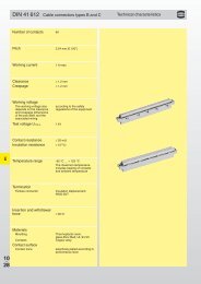
<strong>Power</strong> <strong>Connectors</strong> Size 1,5 (M 40)<br />
Mechanical Data<br />
Housing<br />
Materials and Technical Data<br />
Copper-Zinc alloy<br />
Die Casting<br />
Housing surface<br />
Nickel plated, other surface upon request<br />
Inserts (for contacts) Thermoplastic Polyamid PA 6 (Nylon 6/6), PBT Fire protection class V-0<br />
Contacts<br />
Brass Alloy<br />
Contact surface at point of contact<br />
Nickel and gold plated (0,25 μm Au)<br />
Minimum mating cycles > 500<br />
Seals / O-Rings<br />
Buna-N standard<br />
optional Viton ® (Viton is a registered trademark of DuPont)<br />
Temperature range<br />
-40° C – 125° C (-40 °F – 257 °F)<br />
Type of contacts<br />
Crimp<br />
Protection<br />
IP 67 / IP 69 K per EN 60 529 (connected), NEMA 4x<br />
Cable diameter range 13 – 28 mm (.51“ – 1.10“)<br />
Electrical Data<br />
Number of positions<br />
Number of contacts<br />
Contact-Ø [mm]<br />
Nominal current 1) [A]<br />
Nominal voltage 2 ) [V~] Degree of Protection 2 3)<br />
Nominal voltage 2 ) [V~] Degree of Protection 3 3)<br />
Test voltage (Breakdown voltage) 4) [V~]<br />
Insulation resistance [mΩ]<br />
Max. contact resistance [mΩ]<br />
3 + 2 + PE 4 + 3 + PE<br />
2 4 4 4<br />
2 3,6 2 3,6<br />
28 55 28 55<br />
300 800 300 800<br />
300 600 300 600<br />
2500 4000 2500 4000<br />
> 10 13 > 10 13<br />
3 1 3 1<br />
1), 2), 3), 4)<br />
See Technical Informations page 14<br />
!<br />
Standard delivery of M 40 (size 1.5) <strong>Power</strong> Connector include Contact Insert<br />
Dimensions and specifications may be changed without prior notice<br />
131
<strong>Power</strong> <strong>Connectors</strong> Size 1,5 (M 40)<br />
Straight Connector, Female Thread<br />
Cable-Ø<br />
Part Number<br />
106<br />
Ø 45,6<br />
V<br />
+ -<br />
U<br />
W<br />
2 + 3 + PE, insert for sockets<br />
13 – 18 mm (.51 – .71“) .....7.710.623.000<br />
17 – 24 mm (.67 – .97“) .....7.710.723.000<br />
21 – 28 mm (.83 – 1.10“) ...7.710.823.000<br />
40<br />
40<br />
Contacts page 136 • Assembly instructions page 145<br />
Straight Connector, Female Thread<br />
Cable-Ø<br />
Part Number<br />
106<br />
Ø 45,6<br />
V<br />
+ -<br />
U<br />
W<br />
1 2<br />
4 + 3 + PE, insert for sockets<br />
13 – 18 mm (.51 – .71“) .....7.710.643.000<br />
17 – 24 mm (.67 – .97“) .....7.710.743.000<br />
21 – 28 mm (.83 – 1.10“) ...7.710.843.000<br />
40<br />
40<br />
Contacts page 136 • Assembly instructions page 145<br />
Straight Connector, Male Thread<br />
Cable-Ø<br />
Part Number<br />
110<br />
M 40 x 1,5<br />
V<br />
- +<br />
W<br />
U<br />
2 + 3 + PE, insert for pins<br />
13 – 18 mm (.51 – .71“) .....7.720.623.000<br />
17 – 24 mm (.67 – .97“) .....7.720.723.000<br />
21 – 28 mm (.83 – 1.10“) ...7.720.823.000<br />
44<br />
40<br />
Contacts page 136 • Assembly instructions page 145<br />
Straight Connector, Male Thread<br />
Cable-Ø<br />
Part Number<br />
110<br />
M 40 x 1,5<br />
V<br />
- +<br />
W<br />
U<br />
2 1<br />
4 + 3 + PE, insert for pins<br />
13 – 18 mm (.51 – .71“) .....7.720.643.000<br />
17 – 24 mm (.67 – .97“) .....7.720.743.000<br />
21 – 28 mm (.83 – 1.10“) ...7.720.843.000<br />
44<br />
40<br />
Contacts page 136 • Assembly instructions page 145<br />
132<br />
Dimensions and specifications may be changed without prior notice
<strong>Power</strong> <strong>Connectors</strong> Size 1,5 (M 40)<br />
Type<br />
Part Number<br />
Panel Connector, Male Thread, Front Mounting<br />
2 + 3 + PE, insert for pins<br />
4 holes Ø 4,5 mm (.18“).....7.740.023.000<br />
V<br />
- +<br />
M 40 x 1,5<br />
4,5<br />
W<br />
U<br />
40<br />
30<br />
51<br />
40<br />
Panel hole<br />
Contacts page 136 • Assembly instructions page 146<br />
Ø 32 + 0,1<br />
Type<br />
Part Number<br />
Panel Connector, Male Thread, Front Mounting<br />
4 + 3 + PE, insert for pins<br />
4 holes Ø 4,5 mm (.18“).....7.740.043.000<br />
V<br />
- +<br />
M 40 x 1,5<br />
4,5<br />
W<br />
U<br />
2 1<br />
40<br />
30<br />
51<br />
40<br />
Panel hole<br />
Contacts page 136 • Assembly instructions page 146<br />
Ø 32 + 0,1<br />
Type<br />
Part Number<br />
Panel Connector with knurled Nut, Front Mounting<br />
2 + 3 + PE, insert for sockets<br />
4 holes Ø 4,5 mm (.18“).....7.744.023.000<br />
V<br />
+ -<br />
Ø 45,6<br />
U<br />
W<br />
Ø 4,5<br />
44,2<br />
40<br />
30<br />
40<br />
Panel hole<br />
Contacts page 136 • Assembly instructions page 146<br />
Ø 32 + 0,1<br />
Type<br />
Part Number<br />
Panel Connector with knurled Nut, Front Mounting<br />
4 + 3 + PE, insert for sockets<br />
4 holes Ø 4,5 mm (.18“).....7.744.043.000<br />
V<br />
+ -<br />
Ø 45,6<br />
U<br />
W<br />
Ø 4,5<br />
1 2<br />
44,2<br />
40<br />
30<br />
40<br />
Panel hole<br />
Contacts page 136 • Assembly instructions page 146<br />
Ø 32 + 0,1<br />
Dimensions and specifications may be changed without prior notice<br />
133
<strong>Power</strong> <strong>Connectors</strong> Size 1,5 (M 40)<br />
Right Angle Panel Connector, Male Thread, rotating<br />
Type<br />
Part Number<br />
96<br />
Ø 4,5<br />
2 + 3 + PE, insert for pins<br />
4 holes Ø 4,5 mm (.18“).....7.743.023.000<br />
69<br />
M 40 x 1,5<br />
40<br />
30<br />
V<br />
- +<br />
Panel hole<br />
W<br />
U<br />
Ø 23<br />
32 + 0,1<br />
Contacts page 136 • Assembly instructions page 147<br />
Right Angle Panel Connector, Male Thread, rotating<br />
Type<br />
Part Number<br />
96<br />
Ø 4,5<br />
4 + 3 + PE, insert for pins<br />
4 holes Ø 4,5 mm (.18“).....7.743.043.000<br />
69<br />
M 40 x 1,5<br />
40<br />
30<br />
V<br />
- +<br />
Ø 23<br />
Panel hole<br />
32 + 0,1<br />
W<br />
U<br />
2 1<br />
Contacts page 136 • Assembly instructions page 147<br />
Panel Connector, Male Thread, Single Hole Mounting<br />
Type<br />
Part Number<br />
M 40 x 1,5<br />
Front mounting, 2 + 3 + PE, insert for pins<br />
Thread M 40 x 1,5 .............7.742.023.000<br />
62,5<br />
50,5<br />
V<br />
- +<br />
Panel hole<br />
W<br />
U<br />
M 40 x 1,5<br />
28<br />
40,2+ 0,1<br />
Contacts page 136 • Assembly instructions page 146<br />
Panel Connector, Male Thread, Single Hole Mounting<br />
Type<br />
Part Number<br />
M 40 x 1,5<br />
Front mounting, 4 + 3 + PE, insert for pins<br />
Thread M 40 x 1,5 .............7.742.043.000<br />
62,5<br />
50,5<br />
V<br />
- +<br />
Panel hole<br />
W<br />
U<br />
M 40 x 1,5<br />
28<br />
40,2+ 0,1<br />
2 1<br />
Contacts page 136 • Assembly instructions page 146<br />
134<br />
Dimensions and specifications may be changed without prior notice
<strong>Power</strong> <strong>Connectors</strong> Size 1,5 (M 40) / Required Contacts<br />
Type of Contact<br />
Contact Arrangement, Mating View<br />
Insert for pins 2 + 3 + PE.....................................................2 x crimp pins 2 mm<br />
......................................................................................4 x crimp pins 3,6 mm<br />
V<br />
- +<br />
W<br />
U<br />
Insert for sockets 2 + 3 + PE ................................................2 x crimp sockets 2 mm<br />
......................................................................................4 x crimp sockets 3,6 mm<br />
V<br />
+ -<br />
U<br />
W<br />
Insert for pins 4 + 3 + PE.....................................................4 x crimp pins 2 mm<br />
......................................................................................4 x crimp pins 3,6 mm<br />
V<br />
- +<br />
W<br />
U<br />
2 1<br />
Insert for sockets 4 + 3 + PE ................................................4 x crimp sockets 2 mm<br />
......................................................................................4 x crimp sockets 3,6 mm<br />
V<br />
+ -<br />
U<br />
W<br />
1 2<br />
Dimensions and specifications may be changed without prior notice<br />
135
<strong>Power</strong> <strong>Connectors</strong> Size 1,5 (M 40) / Contacts<br />
Contacts<br />
Type of Contact Crimp Range Part Number<br />
Crimp pin 2 mm, machined .......0,5 – 4 mm 2 (AWG 20 – 12) ......7.015.952.001<br />
Crimp socket 2 mm, machined ...0,5 – 4 mm 2 (AWG 20 – 12) ......7.015.952.002<br />
Crimp pin 3,6 mm, machined ....1,5 – 4 mm 2 (AWG 16 – 12) ......7.015.953.601<br />
Crimp socket 3,6 mm, machined..1,5 – 4 mm 2 (AWG 16 – 12) ......7.015.953.602<br />
Crimp pin 3,6 mm, machined ....6 mm 2 (AWG 10) ......................7.015.953.611<br />
Crimp socket 3,6 mm, machined..6 mm 2 (AWG 10) ......................7.015.953.612<br />
Crimp pin 3,6 mm, machined ....10 mm 2 (AWG 8) ......................7.015.953.621<br />
Crimp socket 3,6 mm, machined..10 mm 2 (AWG 8) ......................7.015.953.622<br />
For appropriate setting of crimp tool see page 148<br />
136 Dimensions and specifications may be changed without prior notice
<strong>Power</strong> <strong>Connectors</strong> Size 1,5 (M 40) / Contacts<br />
Type<br />
Part Number<br />
Contacts<br />
Crimp pin 3,6 mm, machined ....16 mm 2 (AWG 6) ......................7.015.953.631<br />
Crimp socket 3,6 mm, machined..16 mm 2 (AWG 6) ......................7.015.953.632<br />
Crimp Tool Settings see page 144<br />
For appropriate setting of crimp tool see page 148<br />
Dimensions and specifications may be changed without prior notice<br />
137
<strong>Power</strong> <strong>Connectors</strong> Size 1,5 (M 40) / Accessories<br />
Accessories<br />
Type<br />
Part Number<br />
Plastic protective cap<br />
for connectors with female thread.......................................7.000.900.152<br />
Plastic protective cap<br />
for connectors with male thread .........................................7.000.900.151<br />
Brass protective cap<br />
for connectors with female thread.......................................7.015.900.103<br />
Brass protective cap<br />
for connectors with male thread .........................................7.015.900.102<br />
Brass protective cap<br />
with rope for connectors with female thread.........................7.015.9S1.003<br />
Brass protective cap<br />
with rope for connectors with male thread ...........................7.015.9S1.002<br />
138 Dimensions and specifications may be changed without prior notice
<strong>Power</strong> <strong>Connectors</strong> Size 1,5 (M 40) / Accessories<br />
Type Part Number Accessories<br />
Adaptor flange<br />
for Straight <strong>Connectors</strong> .....................................................7.010.900.129<br />
Adapter for Conduit Fittings<br />
Snapflex 25.......................7.010.900.214<br />
DN 23 ..............................7.010.900.215<br />
Snapflex 32.......................7.010.900.216<br />
DN 29 ..............................7.010.900.217<br />
Crimp tool for manual crimping<br />
of machined crimp contacts up to 10 mm 2 (AWG 8)<br />
for power connectors ........................................................7.000.900.902<br />
See page 140 / 141 for crimp tool instructions and page 144 for proper setting<br />
Crimp tool for manual crimping<br />
of machined crimp contacts 16 mm 2 (AWG 6) ......................7.000.900.903<br />
See page 142 / 143 for crimp tool instructions and page 144 for proper setting<br />
Dimensions and specifications may be changed without prior notice<br />
139
NO.<br />
Crimp Tool for <strong>Power</strong> <strong>Connectors</strong> Size 1,5 (M 40)<br />
Crimp Tool<br />
Type<br />
Part Number<br />
Crimp tool .......................................................................7.000.900.902<br />
Application<br />
The four indent crimp tool 7.000.900.902 has been developed for optimal crimping of<br />
machined contacts with diameters from 1 to 10 mm 2 (18 through 8 AWG).<br />
How to Crimp<br />
The reference table indicates the correct locator position to be selected and the crimp<br />
depth to be adjusted for the contact to be crimped. The contact is then inserted through<br />
the access hole of the tool on the opposite side of the locator. The contact is held in place<br />
by closing the handles to the first lock-in position thus preventing the contact from falling<br />
out of the tool and facilitating insertion of the wire into the contact.<br />
The precision ratchet assures consistently accurate crimping every time by forcing the tool<br />
to be closed all the way completing the crimping cycle before the tool can be opened<br />
again.<br />
Exchange of the Locator<br />
The locator can be exchanged by removing the socket head cap screw with a socket wrench.<br />
It can then be disassembled from the hex head screw by turning it counter-clockwise.<br />
Tool in open position<br />
Tool in closed position<br />
Retainer ring<br />
Black<br />
Red<br />
Selector knob<br />
Selector knob<br />
1<br />
Safety clip<br />
140<br />
Dimensions and specifications may be changed without prior notice
Crimp Tool for <strong>Power</strong> <strong>Connectors</strong> Size 1,5 (M 40)<br />
Setting Up Instructions<br />
1. Tool must be in open position<br />
2. Place selected single position head assembly onto retainer ring with alignment pin in<br />
alignment pin hole<br />
3. After single position head is seated against retainer ring, tighten socket head screws<br />
with 9/64 inch socket head screw key<br />
4. Refer to dataplate on single position head. From the proper wire size column,<br />
determine the secector number that corresponds with the contact being used<br />
5. Remove spring clip lock wire from selector knob. Raise selector knob and rotate until<br />
selector number is in line with index mark. Replace spring clip lock wire (optional)<br />
Crimping Instructions<br />
1. Insert contact and prepared wire through the indenter opening into positioner<br />
2. Squeeze handles together until ratchet releases. Handle will return to open position.<br />
Remove crimped contact and wire<br />
Removing Single Position Head<br />
Loosen socket head screws until threads are disengaged from retainer ring and remove<br />
with a straightlifting motion<br />
Crimp Tool<br />
Gaging Instructions<br />
The correct function of the crimp tool has to be checked with a gage (item no. 7.010.900.117).<br />
„GO“-Gaging (green)<br />
Operate tool to fully closed position. Maintain firm hand pressure on the tool handles.<br />
Insert „GO“ gage end. Gage must pass freely between indenter tips.<br />
„NO-GO“-Gaging (red)<br />
Operate tool to fully closed position. Maintain firm hand pressure on the tool handles.<br />
Insert „NO-GO“ gage end. The „NO-GO“ gage may partially enter the indenter opening,<br />
but must not pass completely through the opening.<br />
Care of Tool<br />
There is virtually no maintenance required. However, it is a good practice to keep intenter<br />
tips free of residual color band deposits and other debris. A small wire brush may be used<br />
for this purpose.<br />
We strongly recommend that you:<br />
1. Do not immerse tools in cleaning solution<br />
2. Do not spray oil into tool to lubricate<br />
3. Do not attempt to disassemble tool or make repairs<br />
This is a precision crimp tool and should be handled as such.<br />
Dimensions and specifications may be changed without prior notice<br />
141
Crimp Tool for <strong>Power</strong> <strong>Connectors</strong> Size 1,5 (M 40)<br />
Crimp Tool Type Part Number<br />
Crimp tool for contacts 16 mm 2 (AWG 6) ............................ 7.000.900.903<br />
Application<br />
The hand crimp tool 7.000.900.903 has been developed for optimal crimping of a large<br />
variety of connectors and terminals by using different interchangeable crimping dies.<br />
Operation<br />
- Select crimp insert and install in tool<br />
- Insert and align crimp contact in tool<br />
- Compress tool until contact is held in place<br />
- Insert conductor into contact<br />
- Fully compress tool (tool will reopen automatically)<br />
- Remove crimped conductor from tool<br />
Die retaining screws<br />
Emergency release<br />
Stationary jaw with upper die<br />
Movable jaw with lower die<br />
Set screw<br />
Adjustment wheel<br />
142<br />
Dimensions and specifications may be changed without prior notice
Crimp Tool for <strong>Power</strong> <strong>Connectors</strong> Size 1,5 (M 40)<br />
Adjustment of crimp force and height<br />
Crimp force adjustment is done in the factory (120 – 180 N when unloaded). Tool<br />
frame and jaws are connected that way, an optimal crimping result will be obtained<br />
based on the hand force indicated above. In case the result (e.g. crimp height, pullout<br />
force, etc.) does not meet the requirements of the plug manufacturer, the following<br />
reasons can be considered:<br />
a) Normal wear of tool<br />
Readjustment possible<br />
b) Worn dies<br />
Dies have to be replaced<br />
The quality personnel is authorized to control and readjust these parameters as<br />
described below:<br />
- Unscrew the set screw by means of a screw driver<br />
- Rotating the adjustment wheel anticlockwise, the crimp force increases<br />
and the crimp height decreases ( + )<br />
- Rotating the adjustment wheel lockwise, the crimp force decreases<br />
and the crimp height increases ( - )<br />
- When readjusting the hand force shall not exceed 180 N<br />
- Before using the tool, the operator has to check the adjustment wheel being<br />
firmly secured by the set screw<br />
Maintenance<br />
Keep the tool clean and properly stored when not in service. The joints need to be<br />
regularly oiled and the circlips securing the bolts have to be always in place. Never<br />
use abrasives or hard material to clean the jaws. Please contact the manufacturer<br />
when the tool needs to be repaired or in case of readjustment problems.<br />
Crimp Tool<br />
Dimensions and specifications may be changed without prior notice<br />
143
Crimp Tool for <strong>Power</strong> <strong>Connectors</strong> Size 1,5 (M 40)<br />
Crimp Tool Setting for HUMMEL Crimp Contacts (Crimp Tool 7.000.900.902)<br />
Part Number Contact Cross Section mm 2 AWG Crimp Tool Setting mm Locator Setting<br />
7.015.952.001 Crimp pin 2 mm 1 17 2 3<br />
1,5 16 3 3<br />
2,5 14 4 3<br />
4 12 4 3<br />
7.015.952.002 Crimp socket 2 mm 1 17 2 1<br />
1,5 16 3 1<br />
2,5 14 4 1<br />
4 12 4 1<br />
7.015.953.601 Crimp pin 3,6 mm 1,5 16 3 2<br />
2,5 14 4 2<br />
4 12 5 2<br />
7.015.953.602 Crimp socket 3,6 mm 1,5 16 3 4<br />
2,5 14 4 4<br />
4 12 5 4<br />
7.015.953.611 Crimp pin 3,6 mm 6 10 5 2<br />
7.015.953.612 Crimp socket 3,6 mm 6 10 5 4<br />
7.015.953.621 Crimp pin 3,6 mm 10 8 7 2<br />
7.015.953.622 Crimp socket 3,6 mm 10 8 7 4<br />
These values are only guidelines and actual conductor cross sections depend on manufacturer tolerances.<br />
Assembly information see page 148<br />
Crimp Tool Setting for HUMMEL Crimp Contacts (Crimp Tool 7.000.900.903)<br />
Part Number Crimp Contact Cross Section mm 2 AWG Crimp Tool Setting<br />
7.015.953.631 Crimp pin 3,6 mm 16 6 die 16<br />
7.015.953.632 Crimp socket 3,6 mm 16 6 die 16<br />
These values are only guidelines and actual conductor cross sections depend on manufacturer tolerances.<br />
Assembly information see page 148<br />
144<br />
Dimensions and specifications may be changed without prior notice
<strong>Power</strong> <strong>Connectors</strong> Size 1,5 (M 40) / Assembly Instructions<br />
Straight Connector, Female Thread / Male Threaded Connector<br />
1.<br />
max. 40mm<br />
2.<br />
7mm<br />
3.<br />
Crimp click<br />
4.<br />
5.<br />
6.<br />
7.<br />
40 40<br />
Dimensions and specifications may be changed without prior notice<br />
145
<strong>Power</strong> <strong>Connectors</strong> Size 1,5 (M 40) / Assembly Instructions<br />
Panel Connector<br />
1.<br />
7mm<br />
2.<br />
Crimp click<br />
3.<br />
4.<br />
146<br />
Dimensions and specifications may be changed without prior notice
7mm<br />
<strong>Power</strong> <strong>Connectors</strong> Size 1,5 (M 40) / Assembly Instructions<br />
Right Angle Panel Connector<br />
1.<br />
4.<br />
2.<br />
Crimp<br />
5.<br />
3.<br />
click<br />
6.<br />
3mm<br />
2mm<br />
Dimensions and specifications may be changed without prior notice<br />
147
Crimping, Assembly and Disassembly<br />
Crimping, Assembly and Disassembly<br />
Crimping<br />
- Strip wire ends 7 mm (.28“)<br />
- Dial appropriate setting of crimp tool (page 144)<br />
- Push crimp contact into opening of crimping tool<br />
- Insert stripped wire into the funnel shaped end of the crimp contact<br />
- Squeeze handles of crimping tool together connect contact to wire<br />
Assembly<br />
- Remove crimped assembly and pull on wire to test connection<br />
- Push into desired position of insert<br />
Note: It is recommended to assemble the large contacts first.<br />
Disassembly of Contacts from Insert<br />
A small screwdriver is needed to remove the contacts from the insert.<br />
- Release the white ring by a screwdriver out of the insert<br />
- Move the misplaced contacts out of the insert<br />
- Enter the ring back into the insert<br />
- Push the contacts back into insert<br />
Shielding<br />
- Assemble strain relief insert with insert<br />
- Fold stranding of the shield back over the first O-Ring of the strain relief insert<br />
- Cut back the overextending braid<br />
!<br />
The stranding of the shield is not allowed to touch the second O-Ring.<br />
Otherwise the assembly may not be proof.<br />
148<br />
Dimensions and specifications may be changed without prior notice