Technical manual EA units CC 55.1 and CC - Watts waterbeveiliging
Technical manual EA units CC 55.1 and CC - Watts waterbeveiliging
Technical manual EA units CC 55.1 and CC - Watts waterbeveiliging

You also want an ePaper? Increase the reach of your titles
YUMPU automatically turns print PDFs into web optimized ePapers that Google loves.
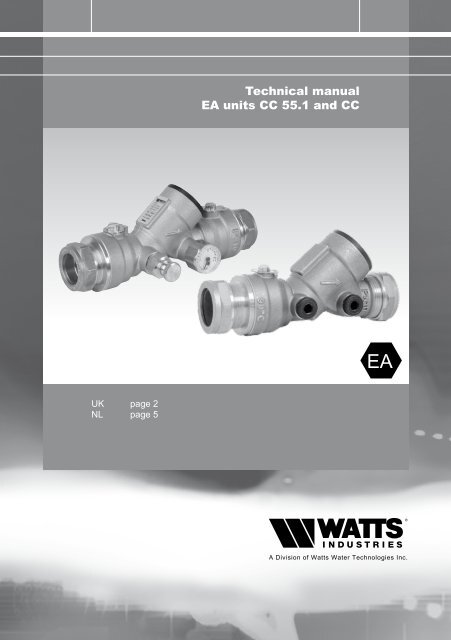
<strong>Technical</strong> <strong>manual</strong><br />
<strong>EA</strong> <strong>units</strong> <strong>CC</strong> <strong>55.1</strong> <strong>and</strong> <strong>CC</strong><br />
<strong>EA</strong><br />
UK page 2<br />
NL page 5
Ea cc <strong>55.1</strong> / <strong>CC</strong><br />
2<br />
St<strong>and</strong>ards<br />
The <strong>CC</strong> <strong>55.1</strong> was developed in<br />
conformance with EN1717.<br />
<strong>EA</strong><br />
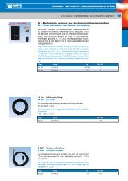
The <strong>Watts</strong> brass controllable check valve<br />
<strong>CC</strong> <strong>55.1</strong> is a fully integrated <strong>EA</strong> check<br />
valve unit with special features, focussed<br />
on easy verification <strong>and</strong> time savings.<br />
Exchanging or cleaning a dirty or damaged<br />
check valve cartridge is now a matter of<br />
simple h<strong>and</strong>ling. For the DN 15 en DN 20<br />
besides the isolation valve on the inlet<br />
side, a pressure gauge <strong>and</strong> a drain valve, a<br />
second isolation valve has been integrated<br />
into the outlet side. It prevents the drinking<br />
water installation downstream the <strong>CC</strong> <strong>55.1</strong><br />
from draining during maintenance <strong>and</strong><br />
Installation guidelines<br />
The Check Valves <strong>CC</strong> <strong>and</strong> <strong>CC</strong> <strong>55.1</strong> can<br />
be used anywhere, according to national<br />
installation legislation (extracted from the<br />
European st<strong>and</strong>ard EN1717), where an <strong>EA</strong><br />
Check Valve must be applied.<br />
replacement. The DN 25 with a 28 mm<br />
compression fitting has been developed<br />
specially for installation in front of a fire reel.<br />
There is already an isolation valve in front of<br />
the fire reel. For this reason the <strong>CC</strong> <strong>55.1</strong><br />
DN 25 has only been given an isolation valve<br />
at the upstream side.<br />
Depending on your application, you might<br />
also order the basic model <strong>CC</strong>, a brass<br />
check valve without pressure gauge <strong>and</strong><br />
drain valve.<br />
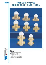
PRESSURE LOSS GRAPH <strong>CC</strong>015-<strong>CC</strong>020-<strong>CC</strong>025<br />
Delta P [kPa]<br />
90<br />
80<br />
70<br />
60<br />
50<br />
40<br />
30<br />
20<br />
10<br />
0<br />
0 1 2 3 4 5 6 7 8<br />
Flow [m 3 /h]<br />
<strong>CC</strong>015 <strong>CC</strong>020 <strong>CC</strong>025
<strong>EA</strong> cc <strong>55.1</strong> / cc<br />
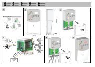
Installation <strong>and</strong> commissioning instructions<br />
Installation of a backflow preventer <strong>EA</strong><br />
<strong>CC</strong> <strong>55.1</strong> shall be carried out by qualified<br />
personnel. Before installing the protection<br />
unit <strong>EA</strong>, the upstream piping shall be flushed<br />
thoroughly.<br />
upstream<br />
upstream<br />
Install a second stop valve directly<br />
downstream of the <strong>EA</strong> <strong>CC</strong> <strong>55.1</strong> DN25<br />
should it not be placed in front of a fire<br />
reel. The <strong>EA</strong> <strong>CC</strong> <strong>55.1</strong> has special holes<br />
for sealing after installation or supervision.<br />
The <strong>EA</strong> <strong>CC</strong> <strong>55.1</strong> should be well accessible<br />
for testing <strong>and</strong> possible replacement of the<br />
plastic check valve module.<br />
downstream<br />
downstream<br />
3<br />
english<br />
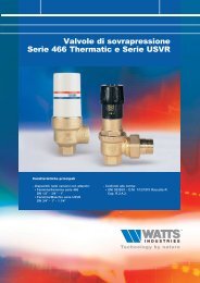
Installation for testing by the st<strong>and</strong>ard method<br />
Instruction for inspection<br />
Pending on the national rules for drinking<br />
water installations, an <strong>EA</strong>-unit should be<br />
tested periodically.<br />
test<br />
test<br />
tap<br />
tap<br />
P<br />
P<br />
Safety unit <strong>EA</strong><br />
Flow<br />
direction<br />
Stop valve 1<br />
Tap/test valve<br />
Unit<br />
Pressure<br />
gauge<br />
Stop<br />
valve 2<br />
Testing procedure <strong>CC</strong> <strong>55.1</strong><br />
1. Close outlet stop valve 2 (with a DN25,<br />
the valve of the fire reel or the stop valve<br />
directly downstream of the <strong>EA</strong>-unit).<br />
2. Close the inlet stop valve 1.<br />
3. Open the tap/test valve.<br />
4. Check with the pressure gauge whether<br />
the indicated pressure remains constant<br />
during min. 30 sec. (= leak tight) or<br />
reduces (= leaking). Replace the check<br />
valve module when leaking.<br />
5. Close the tap/ test valve.<br />
6. Open stop valve 1.<br />
7. Open stop valve 2 (with the DN 25, the<br />
stop valve directly downstream of the<br />
<strong>EA</strong>-unit).
Ea cc <strong>55.1</strong> / <strong>CC</strong><br />
4<br />
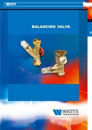
Dimensions<br />
A B C<br />
<strong>CC</strong> <strong>55.1</strong> DN15 65 60 140<br />
<strong>CC</strong> <strong>55.1</strong> DN20 70 65 160<br />
<strong>CC</strong> <strong>55.1</strong> DN25 75 78 155<br />
Article number Type DN Fittings<br />
228015200 <strong>CC</strong> <strong>55.1</strong> 15 15 mm Compression fittings<br />
228020200 <strong>CC</strong> <strong>55.1</strong> 20 22 mm Compression fittings<br />
228025200 <strong>CC</strong> <strong>55.1</strong> 25 28 mm Compression fittings<br />
228015201 <strong>CC</strong> 15 15 mm Compression fittings<br />
228020201 <strong>CC</strong> 20 22 mm Compression fittings<br />
228025201 <strong>CC</strong> 25 28 mm Compression fittings<br />
Material specifications<br />
Body<br />
Brass<br />
Check Valve Polymer<br />
Check Valve seal Rubber<br />
Bleeding Valve Brass<br />
Ball valve<br />
Stainless Steel<br />
Pressure Gauge Brass<br />
<strong>Technical</strong> specifications<br />
Operating pressure PN 10<br />
Nominal operating 65 °C<br />
temperature<br />
Peak temperature 90 °C<br />
during 1 hour/day<br />
(Gauge: max. 70 °C)<br />
Nominal diameter DN 15, DN 20, DN 25<br />
Connections 15, 22, 28 mm<br />
Compression fittings<br />
Approvals<br />
Kiwa<br />
The photos <strong>and</strong> description contained in this brochure are solely intended as an indication, <strong>Watts</strong> Industries<br />
reserves the right to make technical <strong>and</strong> design changes to its products without prior notice.
<strong>EA</strong> cc <strong>55.1</strong> / cc<br />
Normering<br />
De <strong>CC</strong> <strong>55.1</strong> is ontwikkeld conform<br />
EN1717.<br />
5<br />
<strong>EA</strong><br />
Installatievoorschrift<br />
Installeer de <strong>CC</strong> <strong>55.1</strong> volgens de<br />
Waterwerkbladen 3.8.<br />
De <strong>CC</strong> kan overal worden ingezet waar<br />
volgens de Waterwerkbladen een <strong>EA</strong><br />
beveiliging moet worden toegepast.<br />
nederl<strong>and</strong>s<br />
De <strong>CC</strong> <strong>55.1</strong> is een volledig geïntegreerde<br />
<strong>EA</strong> Beveiligingseenheid met bijzondere<br />
mogelijkheden, gericht op eenvoudige<br />
controle en tijdwinst. Het uitwisselen of<br />
reinigen van een vervuilde keerklep is een<br />
kwestie van enkele simpele h<strong>and</strong>elingen<br />
geworden. Bij de DN 15 en DN 20 is er<br />
naast de afsluiter aan de intredezijde, een<br />
manometer en controlekraan, ook een<br />
afsluiter aan de uittredezijde geïntegreerd.<br />
Hierdoor wordt voorkomen dat bij werkzaamheden<br />
de leiding achter de <strong>CC</strong> <strong>55.1</strong><br />
leegloopt. De DN 25 met een 28 mm<br />
knelaansluiting is speciaal ontwikkeld voor<br />
plaatsing vóór een br<strong>and</strong>slanghaspel. Omdat<br />
vóór de haspel reeds een afsluiter aanwezig<br />
is, is de <strong>CC</strong> <strong>55.1</strong> DN 25 alleen voorzien van<br />
een afsluiter aan de intredezijde.<br />
Afhankelijk van het gebruik is het ook<br />
mogelijk om een basisuitvoering<br />
(type <strong>CC</strong>) te bestellen, zonder de<br />
manometer en controlekraan.<br />
PRESSURE LOSS GRAPH <strong>CC</strong>015-<strong>CC</strong>020-<strong>CC</strong>025<br />
Delta P [kPa]<br />
90<br />
80<br />
70<br />
60<br />
50<br />
40<br />
30<br />
20<br />
10<br />
0<br />
0 1 2 3 4 5 6 7 8<br />
Flow [m 3 /h]<br />
<strong>CC</strong>015 <strong>CC</strong>020 <strong>CC</strong>025
Ea cc <strong>55.1</strong> / <strong>CC</strong><br />
Installatie en ingebruikname instructies<br />
6<br />
De installatie en de ingebruikname van<br />
een <strong>EA</strong> terugstroombeveiligingseenheid<br />
<strong>CC</strong> <strong>55.1</strong> dient uitgevoerd te worden door<br />
een erkende installateur.<br />
Spoel voor de plaatsing van de beveiligingseenheid<br />
de toevoerleiding goed door.<br />
bovenstrooms<br />
bovenstrooms<br />
Installeer een tweede afsluiter direct<br />
benedenstrooms van de <strong>CC</strong> <strong>55.1</strong>/<strong>CC</strong> DN 25<br />
indien deze niet vóór een br<strong>and</strong>slanghaspel<br />
geplaatst wordt. De <strong>EA</strong> <strong>CC</strong> <strong>55.1</strong> is voorzien<br />
van verzegelgaatjes. Hierdoor kan de<br />
beveiliging na installatie verzegeld worden.<br />
De <strong>EA</strong> <strong>CC</strong> <strong>55.1</strong> moet goed bereikbaar zijn<br />
voor toetsing en mogelijke vervanging van<br />
de plastic keerklep benedenstrooms<br />
module.<br />
benedenstrooms<br />
test<br />
test<br />
Controleopstelling st<strong>and</strong>aardmethode (norm WWB 1.4G/18.3)<br />
Instructie periodieke controle<br />
In overeenstemming met de nationale<br />
richtlijnen moet een <strong>EA</strong> keerklep periodiek<br />
gecontroleerd worden. De wijze van controle<br />
staat beschreven in paragraaf 18.3 van het<br />
Waterwerkblad 1.4G<br />
P<br />
P<br />
aftap<br />
aftap<br />
Beveiligingseenheid <strong>EA</strong><br />
Stroming<br />
Stopkraan 1<br />
Aftapkraan/testpoort<br />
Unit<br />
Manometer<br />
Stopkraan<br />
2<br />
Werkwijze controle <strong>CC</strong> <strong>55.1</strong><br />
1. Sluit stopkraan 2 (bij de DN 25 de<br />
haspelkraan of de stopkraan direct<br />
benedenstrooms van de <strong>EA</strong> eenheid).<br />
2. Sluit stopkraan 1.<br />
3. Open de aftapkraan/testpoort.<br />
4. Controleer op de manometer of de<br />
aangegeven druk gedurende minimaal<br />
30 s. constant blijft (=lekdicht) of<br />
afneemt (=lek).<br />
Vervang keerklep module indien lek.<br />
5. Sluit de aftap/testkraan.<br />
6. Open stopkraan 1.<br />
7. Open stopkraan 2 (bij de DN 25 de<br />
stopkraan direct benedenstrooms van<br />
de <strong>EA</strong> eenheid).
<strong>EA</strong> cc <strong>55.1</strong> / cc<br />
Afmetingen<br />
A B C<br />
<strong>CC</strong> <strong>55.1</strong> DN15 65 60 140<br />
<strong>CC</strong> <strong>55.1</strong> DN20 70 65 160<br />
<strong>CC</strong> <strong>55.1</strong> DN25 75 78 155<br />
7<br />
nederl<strong>and</strong>s<br />
Artikelnummer Type DN aansluiting<br />
228015200 <strong>CC</strong> <strong>55.1</strong> 15 15 mm knel<br />
228020200 <strong>CC</strong> <strong>55.1</strong> 20 22 mm knel<br />
228025200 <strong>CC</strong> <strong>55.1</strong> 25 28 mm knel<br />
228015201 <strong>CC</strong> 15 15 mm knel<br />
228020201 <strong>CC</strong> 20 22 mm knel<br />
228025201 <strong>CC</strong> 25 28 mm knel<br />
Materiaal specificaties<br />
Huis<br />
Messing<br />
Keerklep<br />
Kunststof<br />
Afdichting keerklep Rubber<br />
Controlekraan Messing<br />
Kogelafsluiter RVS<br />
Manometer Messing<br />
Technische specificaties<br />
Werkdruk PN 10<br />
Nominale 65 °C<br />
Werktemperatuur<br />
Piektemperatuur 90 °C<br />
gedurende 1 uur/dag<br />
(manometer: max.<br />
70 °C)<br />
Diameter nominaal DN 15, DN 20, DN 25<br />
Aansluiting 15, 22, 28 knel<br />
Keuren<br />
Kiwa<br />
De in deze brochure opgenomen foto’s en beschrijvingen hebben een informatieve waarde en zijn niet bindend,<br />
<strong>Watts</strong> Industries behoudt zich het recht voor zonder voorafga<strong>and</strong>e waarschuwing alle technische en uiterlijke<br />
wijzigingen in haar producten aan te brengen, die zij nodig acht.
Product range <strong>Watts</strong> Industries<br />
- System Disconnectors<br />
- Backflow Protection Devices<br />
- Check Valves<br />
- Safety Units<br />
- Safety Relief Valves<br />
- Pressure Reducing Valves<br />
- Automatic Control Valves<br />
- Butterfly Valves<br />
- Shut-Off Valves<br />
- Measuring Gauges<br />
- Temperature Control<br />
- Expansion Vessels<br />
- Process Switches<br />
- Fuel Products<br />
- Gas Products<br />
- Electronic Controls<br />
- Installation Protection Products<br />
- Radiator Valves<br />
- System Products<br />
- Manifolds <strong>and</strong> Fittings<br />
W-011-NL-11/07<br />
<strong>Watts</strong> Industries Netherl<strong>and</strong>s B.V.<br />
Kollergang 14, 6961 LZ Eerbeek, The Netherl<strong>and</strong>s<br />
Phone +31 313 673 700 - Fax +31 313 652 073<br />
E-mail info@wattsindustries.nl<br />
Sites www.wattsindustries.com<br />
www.<strong>waterbeveiliging</strong>.nl - www.waterprotection.com