Models SG-WAC-15ESE SG-WAC-18ESE SG-WAC ... - Air & Water
Models SG-WAC-15ESE SG-WAC-18ESE SG-WAC ... - Air & Water
Models SG-WAC-15ESE SG-WAC-18ESE SG-WAC ... - Air & Water

You also want an ePaper? Increase the reach of your titles
YUMPU automatically turns print PDFs into web optimized ePapers that Google loves.
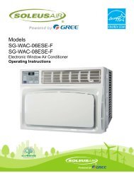
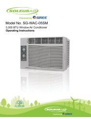
<strong>Models</strong><br />
<strong>SG</strong>-<strong>WAC</strong>-<strong>15ESE</strong><br />
<strong>SG</strong>-<strong>WAC</strong>-<strong>18ESE</strong><br />
<strong>SG</strong>-<strong>WAC</strong>-25ESE<br />
Electronic Window <strong>Air</strong> Conditioner<br />
Operating Instructions
Thank you for choosing a Soleus <strong>Air</strong> powered by Gree <strong>Air</strong> Conditioner. This owner’s manual will<br />
provide you with valuable information necessary for the proper care and maintenance of your new<br />
product. Please take a few moments to thoroughly read the instructions and familiarize yourself with<br />
all the operational aspects of your new air conditioner.<br />
For your own records, please attach a copy of your sales receipt to this manual. Also, write the store<br />
name/location, date purchased, and serial number below:<br />
Store Name: ____________________________________________________<br />
Location: ______________________________________________________<br />
Date Purchased: _________________________________________________<br />
Serial Number (located on back of unit): ______________________________<br />
IMPORTANT SAFETY INSTRUCTIONS<br />
Before installing and using your air conditioner, please read this owner’s manual carefully. Store this<br />
manual in a safe place for future reference. Your safety and the safety of others is very important to<br />
us. Please pay attention to all safety messages outlined in this owner’s manual.<br />
WARNING: To reduce the risk of fire, electrical shock or injury when using your air conditioner, follow<br />
the following basic precautions:<br />
• Plug into a grounded 3 prong outlet.<br />
• Do not remove the ground prong.<br />
• Do not use a plug adapter.<br />
• Do not use an extension cord.<br />
• Unplug the air conditioner before servicing<br />
• Use two or more people to move and install the air<br />
conditioner<br />
This is a safety alert symbol.<br />
This symbol alerts you to potential hazards that can harm you or others or even cause<br />
death.<br />
All safety messages will directly follow the safety alert symbol and/or the words<br />
“DANGER” or “WARNING”.<br />
Failure to immediately follow these<br />
instructions may cause serious injury<br />
or even death.<br />
All Safety messages alert you of potential hazards, how to reduce the chance of injury,<br />
and what can happen if instructions are not followed correctly.<br />
2
ELECTRICAL REQUIREMENTS<br />
The electrical ratings for your air conditioner are listed on the model and serial<br />
number label located on the front left side of the unit (when facing the front).<br />
Specific electrical requirements are listed in the chart below. Follow the<br />
requirements below for the type of plug on the power supply cord.<br />
Wiring Requirement<br />
Power Supply Cord<br />
Electrical Shock Hazard<br />
Plug into a grounded 3 prong outlet.<br />
Do not remove the ground prong.<br />
Do not use an adapter<br />
Do not use an extension cord.<br />
Failure to follow these instructions can result in death,<br />
fire, or electrical shock<br />
208~230 Volt (197.2 min. - 253 max.)<br />
0-20 amps<br />
20-amp time-delay fuse or<br />
Use on single outlet circuit only<br />
Recommended Ground Method<br />
For your personal safety, this air conditioner must be grounded. This air conditioner is equipped with a 3 prong power<br />
supply cord with a grounded plug. To minimize the possibility of electrical shock, the cord must be plugged into a 3 prong<br />
outlet and grounded in accordance with all local codes and ordinances. If a 3 prong outlet is not available, it is the customer’s<br />
responsibility to have a properly grounded 3 prong outlet installed by a qualified electrician.<br />
It is the customer’s responsibility:<br />
• To contact a qualified electrician<br />
• To assure that the electrical installation is adequate<br />
and in conformance with the National Electrical Code,<br />
ANSI/NFPA 70 - latest edition, and all local codes and<br />
ordinances.<br />
Copies of the standards listed may be obtained from:<br />
National Fire Protection Association<br />
One Batterymarch Park<br />
Quincy, Massachusetts 02269<br />
LCDI Power Cord and Plug<br />
This air conditioner is equipped with an LCDI (Leakage Current Detection and Interruption) power cord and plug as<br />
required by US National Electric Code 440.65. This cord consists of a length of shielded flexible cord with no termination<br />
on the load side and a LCDI attachment plug on the line side.<br />
The LCDI power cord and plug will remove the supply source via electrical disconnect (circuit trip) if the nominal current<br />
leakage between the cord shield and either load conductor exceeds a predetermined value. The cord will remain deenergized<br />
until the devise has been manually reset. This is intended to reduce the risk of a fire in the power cord or<br />
combustible materials nearby. The cord shields are not grounded and they must be considered a shock hazards if<br />
exposed. The cord shield must not be connected to ground or to any exposed metal.<br />
The test and reset buttons on the LCDI Plug are used to check if<br />
the plug is functioning properly. To test the plug:<br />
1. Plug power cord into a wall outlet<br />
2. Press the TEST Button, the circuit should trip and cut all<br />
power to the air conditioner<br />
3. Press the RESET button for use<br />
If a test is performed and the indicator light remains ON, the<br />
current leakage has been detected. Do not use the air<br />
conditioner or attempt to reset the LCDI Plug. Contact Customer<br />
Service for troubleshooting recommendations.<br />
3
PARTS LIST<br />
25ESE 25ESE<br />
15/<strong>18ESE</strong><br />
WINDOW SASH SEAL<br />
ROUND HEAD<br />
SAFETY LOCK AND<br />
3/4" ROUND-HEAD<br />
SCREW<br />
WASHER HEAD<br />
LOCKING SCREW<br />
(on 25ESE models)<br />
FOAM GASKET<br />
TOP ANGLE<br />
FRAME<br />
ASSEMBLY<br />
(LEFT)<br />
SIDE RETAINER<br />
3<br />
7/8<br />
SEAL-BOTTOM RAIL TO UNIT<br />
1/2" LONG<br />
SCREWS AND<br />
LOCKNUTS<br />
FRAME<br />
ASSEMBLY<br />
(RIGHT)<br />
LOCKNUT<br />
3/4" LONG<br />
FLAT HEAD<br />
BOLT<br />
SILLANGLE<br />
BRACKET<br />
WINDOW SUPPORT<br />
BRACKET<br />
TOOLS NEEDED<br />
Large Flathead Screwdriver<br />
Tape Measurer<br />
Adjustable Wrench or Pliers<br />
Pencil<br />
Level<br />
Socket Wrenches<br />
Phillips Head Screwdriver<br />
Non-Hardware Packing List<br />
• Window <strong>Air</strong> Conditioner<br />
• AAA Batteries (2) & Remote Control<br />
• Top Mounting Rail<br />
• Foam Top Mounting Rail Seal Strip<br />
• Accordion Panels (2)<br />
• Side Retainer (2)<br />
• Window Sash Seal<br />
• Foam Seal for Bottom Rail<br />
• Owner’s Manual<br />
4
SPECIFICATIONS<br />
• Noise level is measured at a distance of 3.28 ft away from the front of the unit in cooling mode.<br />
• Power consumption is measured when the fan runs at the highest speed setting.<br />
• These specifications are for reference only. For actual data, please refer to the rating label on the unit.<br />
Model<br />
<strong>SG</strong>-<strong>WAC</strong>-<strong>15ESE</strong><br />
Power Supply (Ph/V/Hz)<br />
1/115/60Hz<br />
Dehumidifying Capacity (Pints/Day) 91.2<br />
Rated Cooling Capacity (BTU/h) 15,000<br />
Rated Heating Capacity (BTU/h) /<br />
Cooling Power Input (Watts) 1400<br />
Heating Power Input (Watts) /<br />
Rated Current Cooling (Amperage) 12<br />
Rated Current Heating (Amperage) /<br />
EER/C.O.P 10.8<br />
Noise Level db (A) Indoor/Outdoor 58/64<br />
CFM 480<br />
Design Pressure (PSIG) (H/L) /<br />
Dimensions (W” x H” x D”) 23.63 x 17.78 x 25.44<br />
Package Dimensions (W” x H” x D”) 28.28 x 19.97x 26.09<br />
Net/Gross Weight (Lbs) 110/129<br />
Refrigerant Charge (Oz) 28.22<br />
<strong>SG</strong>-<strong>WAC</strong>-<strong>18ESE</strong><br />
1/230-208/60Hz<br />
129.6<br />
18,000 /17,600<br />
/<br />
1680 /1650<br />
/<br />
8.1/8.8<br />
/<br />
10.7<br />
59/64<br />
480<br />
/<br />
23.63 x 17.78 x 25.44<br />
28.28 x19.97 x 26.09<br />
110/125<br />
28.75<br />
<strong>SG</strong>-<strong>WAC</strong>-25ESE<br />
1/230-208/60Hz<br />
192<br />
24,500/24,000<br />
/<br />
2600 /2550<br />
/<br />
11.6/12.6<br />
/<br />
9.4<br />
59/64<br />
400-490<br />
/<br />
26.54x 18.62 x26.30<br />
28.94x 20.1 x 31.69<br />
135/152<br />
40.56<br />
5
INSTALLATION & ASSEMBLY INSTRUCTIONS<br />
Window Preparation<br />
Please read all instructions prior to installing your air conditioner. Two people are recommended to install this product. If<br />
a new electrical outlet is required, have the outlet installed by a qualified electrician before installing the unit.<br />
Before installing the unit, check the dimensions of your window to make sure the air conditioner will fit. This unit is made<br />
to fit inside a standard double-hung window. Make sure the window is in good shape and able to firmly hold the needed<br />
screws. If not, make repairs prior to installing the unit.<br />
Model <strong>SG</strong>-<strong>WAC</strong>-25ESE <strong>SG</strong>-<strong>WAC</strong>-<strong>15ESE</strong> / <strong>SG</strong>-<strong>WAC</strong>-<strong>18ESE</strong><br />
Unit Height 18 5/8” 17 5/8”<br />
Unit Width 26 1/2” 23 1/2”<br />
Min. Window Opening 19” 18 1/2”<br />
Min. Window Width 31” 26 1/2”<br />
Max Window Width 43” 40 1/2”<br />
Storm Window Requirements<br />
A storm window frame will not allow the air conditioner to tilt properly which in turn will keep it from draining properly. To<br />
adjust for this, attach a board or piece of wood to the sill. The board or wood piece should have a depth of at least 1 1/2”.<br />
Make sure the board or piece of wood is approximately 1/2” higher than the storm window frame. This will allow the air<br />
conditioner to tilt enough for proper drainage. (See FIG. 1).<br />
FIG. 1<br />
SASH<br />
STORM<br />
WINDOW<br />
FRAME<br />
1 1/2” MIN<br />
(38 mm)<br />
Board or wood<br />
piece must be<br />
approximately<br />
1/2” higher<br />
than the storm<br />
window frame<br />
for proper<br />
drainage<br />
Prior to Installing the <strong>Air</strong> Conditioner<br />
1. Check for anything that could block airflow. Check the area outside of the window for things such as shrubs, trees, or<br />
awnings. Check the inside area to make sure curtains, drapes, or blinds will not prevent proper airflow.<br />
2. Check the available electrical outlet. The power supply must be the same as shown on the unit serial nameplate<br />
(located on the left side of the unit, near the front faceplate). Be sure the outlet is close enough for the power cord to<br />
reach.<br />
3. Carefully unpack the air conditioner. Remove all packing material and make sure the floor is protected when removing.<br />
Due to the large size of this air conditioner, two people should move the unit together.<br />
When handling the unit, be careful to avoid cuts from<br />
the sharp metal edges and aluminum fins on the front<br />
and rear coils.<br />
6
INSTALLATION & ASSEMBLY INSTRUCTIONS - WINDOW MOUNTING<br />
REMOVE CHASSIS<br />
1. Pull down the front panel and remove the filter (FIG. 1 below)<br />
2. Lift the front panel upwards to remove and place to the side.<br />
FIG. 1<br />
FIG. 2<br />
3. Locate the four faceplate screws and remove. These screws will need to be re-installed prior to mounting the air conditioner<br />
(FIG. 2 above)<br />
4. After removing the screws, gently pull away the faceplate from the air conditioner cabinet (FIG. 3 & 4).<br />
FIG. 3 FIG. 4<br />
5. Remove the shipping screws from the top of the unit (<strong>SG</strong>-<strong>WAC</strong>-25ESE only) and both sides of the cabinet if installed.<br />
6. Remove the two screws on the top of the chassis that hold the cabinet to the unit. Hold the cabinet while pulling on<br />
the base of the chassis and remove the chassis from the cabinet (FIG. 5).<br />
7. Add two foam inserts to the holes on top of the cabinet where the shipping screws were located.<br />
8. There may be internal packing protection on the <strong>SG</strong>-<strong>WAC</strong>-25ESE. This packing material must be removed prior to<br />
installation (FIG. 6)<br />
FIG. 5<br />
FIG. 6<br />
7
ASSEMBLY & INSTALLATION (CONT.)<br />
Top Angle Rail and Side Bracket Installation<br />
1. Place the air conditioner on a hard flat surface.<br />
2. Locate the foam gasket and top angle rail<br />
3. Attach the foam gasket to the top angle rail.<br />
4. Install top angle side to cabinet as shown in FIG. 7.<br />
Foam Gasket and Top<br />
Angle Rail<br />
FIG. 7<br />
FIG. 9<br />
TOP VIEW<br />
8. Once the window panels are correctly installed, for 25K<br />
insert the washer head locking screws on the top rail and<br />
frame. Do not tighten all the way at this time. Allow the<br />
bottom frame to slide freely.<br />
Placing the Cabinet Inside the Window<br />
1. Open the window and place the cabinet in the middle<br />
of the window sill.<br />
2. Make sure the bottom rail is seated over the window<br />
sill as shown below. Bring the window down temporarily<br />
behind the top angle rail to hold the cabinet in place.<br />
5. Slide "I" section of window filler panel into side retainer.<br />
Do both sides.<br />
FIG. 8a<br />
SIDE RETAINER<br />
SILL<br />
WINDOW FILLER PANEL<br />
BOTTOM<br />
RAIL<br />
SIDE RETAINER<br />
WINDOW FILLER<br />
PANEL<br />
6. Insert top and bottom legs of window filler panel frame<br />
into channel in the top angle and bottom rail. Do both<br />
sides(see FIG 8b-9)<br />
7. Install side retainer to cabinet as shown in<br />
FIG.8b-9.<br />
PLASTIC<br />
FRAME<br />
FIG. 8b<br />
3. Fasten cabinet to window sill using two 7/8” Roundhead<br />
screws (3/4” ROUND-Head screws on <strong>SG</strong>-<strong>WAC</strong>-<br />
25ESE). Pre-drill holes if needed. Add the bottom rail<br />
seal over the screws.<br />
SIDE RETAINER<br />
ROUND-HEAD SCREW<br />
3/4"for 25ESE<br />
7/8"for 15/<strong>18ESE</strong><br />
WINDOW FILLER<br />
PANEL<br />
8
ASSEMBLY & INSTALLATION (CONT.)<br />
Install Support Brackets<br />
1. Hold each support bracket flush against the outside of<br />
the window sill. Tighten each bracket to the bottom of<br />
the cabinet as shown below. Mark the brackets at top<br />
lever of the window sill and then remove.<br />
Extend the Accordion Panels<br />
1. Carefully raise the window to expose the accordion<br />
panel and panel frame. Loosen the locking screws so<br />
the accordion panels slide easily.<br />
Locking Screw<br />
For 24K<br />
Sill Angle<br />
Bracket<br />
Mark<br />
Left<br />
Locknut<br />
Flat Head Bolt<br />
1/2” Long Screws<br />
and Locknuts<br />
Right<br />
3/4" Round-<br />
Head Screw<br />
for 14/18K<br />
2. Extend each panel to completely fill the width of the<br />
window. Tighten the locking screws when the panels<br />
are fully extended.<br />
3. Close window behind top angle.<br />
4. Set a locking screw on both sides of the curtain as shown.<br />
Install the Window Lock and Sash Seal<br />
1. Trim the sash seal to fit the width of the window. Insert<br />
the sash seal into space between the upper and lower<br />
sashes.<br />
2. Assemble the sill angle brackets to the support brackets<br />
at the marked position as shown above. Hand<br />
tighten, but not all the way for any changes that may<br />
need to be made later during installation.<br />
3. Install the support brackets (with sill angle brackets<br />
attached) to the bottom of the cabinet as shown below.<br />
4. Tighten all 6 bolts securely.<br />
2. Attach the right angle safety lock as shown below.<br />
1/2” long<br />
screw and<br />
locknuts<br />
9
ASSEMBLY & INSTALLATION (CONT.)<br />
Installing the Chassis into the Cabinet<br />
1. Team lift (two people) the air conditioner chassis and<br />
carefully slide it into the cabinet. Let the front of the air<br />
conditioner hang out approximately 6”.<br />
2. DO NOT PUSH ON THE CONTROLS OR FINNED<br />
COILS.<br />
3. Be sure the chassis is firmly seated in the back of the<br />
cabinet.<br />
4. Insert all screws removed during window installation<br />
and reattach the front face plate, front panel, and the<br />
air filter. Use the REMOVE CHASSIS instructions and<br />
figures 1-6 for reference.<br />
THRU-THE-WALL INSTALLATION<br />
NOTE: Consult local building codes prior to installation<br />
and/or a qualified carpenter.<br />
Select the Wall Location<br />
This air conditioner has a slide-out chassis, so that it can<br />
be installed through an outside wall as specified below:<br />
Model <strong>SG</strong>-<strong>WAC</strong>-25ESE <strong>SG</strong>-<strong>WAC</strong>-<strong>15ESE</strong> /<br />
<strong>SG</strong>-<strong>WAC</strong>-<strong>18ESE</strong><br />
Max Wall<br />
Thickness<br />
12” 10”<br />
IMPORTANT: The side louvers must never be blocked.<br />
NOTE: All parts needed for Thru-The-Wall Installation are<br />
provided, except a wood frame, shims, and 10 wood<br />
screws (10-1” long minimum). Select a wall surface that:<br />
1. Does not support major structural loads such as the<br />
frame construction at ends of windows, and under<br />
truss-bearing points, etc.<br />
2. Does not have plumbing or wiring inside.<br />
3. Is near existing electrical outlets, or where another outlet<br />
can or will be installed.<br />
4. Does not have objects blocking the air vents which<br />
limits cooling.<br />
5. Allows unblocked airflow from the rear and sides of the<br />
air conditioner.<br />
Prepare the Wall<br />
1. Prepare the wall in frame construction (including brick<br />
and stucco veneer). Working from inside the room, find<br />
the wall stud that is nearest the center of the installation<br />
area.<br />
FIG. 1<br />
10
ASSEMBLY & INSTALLATION - THRU-THE-WALL (CONT.)<br />
Carefully measure and cut an opening with the following<br />
dimensions depending on your model (FIG. 1 & 2).<br />
WIDTH “X” = inside model plus twice the thickness of the<br />
framing material used.<br />
HEIGHT “Y” = inside model height plus twice the thickness<br />
of framing material used.<br />
Model <strong>SG</strong>-<strong>WAC</strong>-25ESE <strong>SG</strong>-<strong>WAC</strong>-<strong>15ESE</strong> /<br />
<strong>SG</strong>-<strong>WAC</strong>-<strong>18ESE</strong><br />
NOTE: If wall thickness is 8-12” or more, add aluminum<br />
flashing over the bottom of the frame opening to assure<br />
water is unable to enter the area between the inner and<br />
outer wall.<br />
Inside Frame<br />
Height<br />
Inside Frame<br />
Width<br />
18 7/8” (47.9 cm) 18” (45.7 cm)<br />
26 3/4” (67.9 cm) 23 7/8” (60.6 cm)<br />
FIG. 2<br />
Prepare and Install the Cabinet<br />
1. Slide the chassis from the cabinet. Refer back to the<br />
REMOVE CHASSIS instructions and FIG. 1-6 in the<br />
WINDOW MOUNTING SECTION.<br />
2. Place the cabinet into the opening with the bottom rail<br />
resting firmly on the bottom board of the wood frame.<br />
3. Position the cabinet so it is tilted properly for water removal<br />
as seen below.<br />
4. Build a wooden frame with the INSIDE dimensions of<br />
your model listed above (Measure twice). The frame<br />
depth should be the same as the wall thickness. Fill in<br />
extra space from the opening to the studs with wood<br />
spacers as shown below.<br />
5. Nail the spacers to the studs. They should be flush with<br />
the dry wall.<br />
4. Secure the bottom rail to the wood frame with two large<br />
1” (2.5 cm) long wood screws as shown below.<br />
11
ASSEMBLY & INSTALLATION - THRU-THE-WALL (CONT.)<br />
MASONRY CONSTRUCTION<br />
Refer to the SUPPORT BRACKET ASSEMBLY in the<br />
WINDOW MOUNTING section to assemble the support<br />
brackets. A wooden strip nailed to the outside wall should<br />
be used in conjunction with the angled sill support brackets.<br />
Support<br />
Bracket<br />
Wooden Strip<br />
5. Screw or nail the cabinet to the wooden frame using<br />
shims if the frame is oversized, to eliminate possible<br />
noise. Remember to maintain proper slope for water<br />
elimination.<br />
1. Cut or build a wall opening in the masonry wall similar<br />
to the frame construction (refer to the THRU-THE-<br />
WALL installation for a wall thickness greater than 8<br />
1/2”)..<br />
2. Secure the cabinet in place using masonry nails, or<br />
masonry anchor screws. Or, build a frame using the<br />
instructions found in the THRU-THE-WALL installation<br />
section.<br />
3. Make sure the masonry above the cabinet is supported<br />
well. Use the existing holes in the cabinet or additional<br />
drilled holes to fasten the cabinet at various positions.<br />
Make sure that the side louvers are clear of any obstructions.<br />
4. Install the exterior cabinet support brackets according<br />
to the SUPPORT BRACKET INSTALLATION instructions<br />
in the THRU-THE-WALL installation section.<br />
Caulk or flash with aluminum if needed. This will provide<br />
a tight seal around the top and sides of the cabinet.<br />
5. For a more aesthetically pleasing installation, apply<br />
wood trim molding around the sides of the cabinet without<br />
obstructing the side louvers.<br />
6. Install the chassis into the cabinet by following the<br />
steps described in the WINDOW MOUNTING section.<br />
OPTIONAL: Caulking and installation of the trim on the<br />
interior wall may be done if desired. Caulk the openings<br />
around the top and sides of the cabinet and all sides of the<br />
wood sleeve to the opening.<br />
NOTE: See the WINDOW MOUNTING instructions for the<br />
bottom rail seal location.<br />
12
USING YOUR AIR CONDITIONER<br />
Electronic Control Panel & Remote Control<br />
This display always shows the room<br />
temperature except when setting<br />
the Set temperature or the Timer.<br />
<strong>Air</strong> Conditioner Controls<br />
1-24Hr Timer<br />
Timer<br />
Decrease<br />
Mode Button<br />
Decrease<br />
Fan Speed<br />
Increase/<br />
Decrease<br />
Temperature<br />
Remote Control<br />
Normal Operating Sounds<br />
When the light is on the unit is in<br />
temperature or timer set mode.<br />
Light Indicates the<br />
Timer is set.<br />
Timer Increase<br />
Auto Fan On<br />
Increase Fan Speed<br />
Power Button<br />
• You may hear a pinging noise caused by water<br />
hitting the condenser, on rainy days, or when the<br />
humidity is high. This design feature helps remove<br />
moisture and improve efficiency.<br />
• You may hear the thermostat click when the compressor<br />
cycles on and off.<br />
• <strong>Water</strong> will collect in the base pan during rain or<br />
days of high humidity. The water may overflow<br />
and drip from the outside part of the unit.<br />
• The fan may run even when the compressor is<br />
not on.<br />
1. Power Button: Turns the air conditioner on and<br />
off<br />
2. Digital Display: Displays the current room temperature<br />
or the amount of time left on the timer.<br />
Shows the Set Temp when setting the temperature.<br />
Shows the Timer Set when setting the timer.<br />
The once the timer and/or temperature are set,<br />
the display will change to show the current room<br />
temperature. To see the set temperature again,<br />
simply press either of the Temp/Delay ▲/▼<br />
buttons.<br />
3. Temperature Set: Use these buttons on the control<br />
panel and remote to increase or decrease the<br />
Set Temperature (the desired room temperature)<br />
in cooling or energy saver mode. The SET light<br />
will light up when setting the temperature<br />
4. Timer Set: Use these buttons on the control<br />
panel and remote to set the Timer. Each press of<br />
the Timer (DELAY) buttons will increase or decrease<br />
the timer. For timer instructions see #7.<br />
5. Fan Speed & Auto Fan: Use the fan speed buttons<br />
to change the fan speed. Choose between<br />
low, medium, high, and Auto. When using the remote<br />
control, press the AUTO button to turn auto<br />
mode on and the FAN+ and FAN– buttons to<br />
select low, medium, or high fan speed.<br />
6. Mode Button: Press the mode button to cycle<br />
through the various modes: Cooling, Energy<br />
Saver, and Fan only.<br />
7. Auto-on Timer: When the air conditioner is off, it<br />
can be set to automatically turn on in 1-24 hours<br />
at the previous set mode and fan setting. To set<br />
the Auto-on Timer, press the DELAY button on<br />
the unit or remote control. Each touch of the ▲/▼<br />
on the unit or the +/- buttons on the remote will<br />
change the timer setting in 1 hour intervals. The<br />
SET light will turn on while setting.<br />
Auto-off Timer: When the air conditioner is on, it<br />
can be set to automatically turn off in 1-24 hours.<br />
To se the Auto-off Timer, press the DELAY button<br />
on the unit or remote control. Each ouch of the ▲/<br />
▼ on the unit or the +/- buttons on the remote will<br />
change the timer setting in 1 hour intervals. The<br />
SET light will turn on while setting.<br />
• To see the remaining time, press the DELAY<br />
Button. To change the timer setting use the<br />
▲/▼ on the unit or the +/- buttons on the<br />
remote.<br />
• To cancel the timer, press the DELAY button<br />
until the SET light turns off.<br />
13
USING YOUR AIR CONDITIONER (Cont.)<br />
• Freezing Conditions: This is a cooling only air<br />
conditioner. It is not designed for freezing outdoor<br />
conditions. It must not be used in freezing outdoor<br />
conditions.<br />
• Remote Control: To ensure proper operation<br />
when using the remote control, aim the remote<br />
directly at the signal receiver on the air conditioner.<br />
• The remote control has a signal range up to<br />
20 feet.<br />
• Make sure nothing is blocking the remote control<br />
signal from being received by the air conditioner.<br />
• Make sure the batteries are installed correctly<br />
and still have power.<br />
• Cooling Mode: Use the COOL mode at Low, Medium,<br />
High, or Auto Fan speed when cooling is<br />
needed. Use the temperature ▲/▼ buttons to set<br />
the desired temperature between 64°F and 86°F.<br />
• Once the temperature is set, the compressor<br />
will cycle on and off to keep the room<br />
temperature at the set temperature level. The<br />
lower the set thermostat temperature, the<br />
cooler the room will become. The higher the<br />
set thermostat temperature, the warmer the<br />
room will become.<br />
• For Normal Cooling - Set the Mode to Cool<br />
and the Fan to High or Med with the<br />
termperature set in the middle.<br />
• For Maximum Cooling - Set the Mode to Cool<br />
and the Fan to High with a lower set<br />
temperature.<br />
• For Quieter & Nighttime Cooling - Set the<br />
Mode to Cool and the Fan to Low with the<br />
temperature set in the middle.<br />
NOTE: If the air conditioner is off and is then<br />
turned on while set to a Cool setting or if<br />
turned from a fan setting to a Cool setting, it<br />
may take approximately 3 minutes for the<br />
compressor to start and cooling to begin.<br />
• Energy Saver Mode - Controls the Fan<br />
On - The fan will cycle on and off with the<br />
compressor. This results in winder variations of room<br />
temperature and humidity. Normally used with the<br />
room is unoccupied. NOTE: The fan my continue to<br />
run for a short time after the compressor cycles off.<br />
Off - The fan runs all the time in fan or cooling mode.<br />
• Fan Only Mode: Use Fan Only mode at Low,<br />
Med, or High fan speed to provide air circulation<br />
and filtering without cooling. Since fan only setting<br />
do not provide cooling, a Set temperature cannot<br />
be entered. The room temperature will appear in<br />
the display.<br />
NOTE: Auto Fan Speed cannot be used in Fan<br />
Only mode.<br />
• Loss of Power Protection: If power to the air<br />
conditioner is lost or interrupted, the air conditioner<br />
will automatically re-start in the setting last<br />
used prior to power loss. If the Timer was set to<br />
automatically turn the air conditioner off or on, it<br />
will resume countdown at the amount time left<br />
prior to power loss. You may need to set a new<br />
time if desired.<br />
• <strong>Air</strong> Direction: Use the lever near on the front air<br />
vents to adjust the direction of the airflow. You<br />
can direct the airflow left or right only. The lever is<br />
located on the right side of the air vent.<br />
14
CARE AND CLEANING<br />
Clean your air conditioner to keep it looking new<br />
and to minimize dust build up.<br />
<strong>Air</strong> Filter Cleaning<br />
The air filter should be checked at least once<br />
every month to see if it needs cleaning. Trapped<br />
particles and dust can build up in the filter and<br />
may decrease airflow as well as cause the<br />
cooling coils to accumulate frost. To clean the air<br />
filter:<br />
1. Remove the filter by pulling down on the indents<br />
of the filter door on the front of the unit.<br />
(See FIG. 13)<br />
2. Wash the filter using liquid dish soap and<br />
warm water. Rinse the filter thoroughly. Gently<br />
shake the filter to remove excess water.<br />
3. Let the filter dry completely before placing it<br />
into the air conditioner.<br />
4. If you do not wish to wash the filter, you may<br />
vacuum the filter to remove the dust and<br />
other particles.<br />
Cabinet Cleaning<br />
To clean the air conditioner cabinet:<br />
• Unplug the air conditioner to prevent shock or<br />
a fire hazard. The cabinet and front panel of<br />
the air conditioner may be dusted with an oilfree<br />
cloth or washed with a cloth dampened in<br />
a solution of warm water and mild liquid soap.<br />
Rinse thoroughly with a damp cloth and wipe<br />
dry.<br />
• Never use harsh cleaners, wax or polish on<br />
the cabinet front.<br />
• Be sure to wring excess water from the cloth<br />
before wiping around the controls. Excess<br />
water in or around the controls may cause<br />
damage to the air conditioner.<br />
Winter Storage<br />
To store the air conditioner when it is not in use<br />
for an extended period of time, remove it carefully<br />
from the window according to the installation<br />
instructions and cover it with plastic or place it in<br />
the original box<br />
.<br />
FIG. 13<br />
Wear and Tear<br />
To minimize wear and tear on the air conditioner,<br />
always wait at least 3 minutes before<br />
changing modes. This will help prevent the<br />
compressor from overheating and the circuit<br />
breaker from tripping.<br />
15
TROUBLESHOOTING<br />
PROBLEM<br />
The <strong>Air</strong> Conditioner will not start<br />
The <strong>Air</strong> Conditioner does not cool<br />
as it should<br />
The <strong>Air</strong> Conditioner is freezing up<br />
The Remote Control is not working<br />
POSSIBLE CAUSES<br />
The air conditioner is unplugged<br />
The fuse is blown/circuit breaker is<br />
tripped.<br />
Power Failure<br />
The current interrupter device is<br />
tripped.<br />
<strong>Air</strong>flow is restricted<br />
The temperature control may not be<br />
set correctly.<br />
The air filter is dirty<br />
The room may be too warm<br />
Cold air is escaping<br />
The Cooling Coils are frozen<br />
Ice blocks the air flow and stops the air<br />
conditioner from cooling the room<br />
The batteries are inserted incorrectly<br />
The batteries may be dead<br />
SOLUTIONS<br />
• Make sure the air conditioner is<br />
plug is pushed completely into the<br />
outlet<br />
• Check the house fuse/circuit<br />
breaker box and replace the fuse<br />
or reset the breaker.<br />
• The unit will automatically re-start<br />
when power is restored.<br />
• There is a protective time delay<br />
(approx. 3 minutes) to prevent<br />
tripping of the compressor<br />
overload. For this reason, the unit<br />
may not start normal cooling for 3<br />
minutes after it is turned back on.<br />
• Press the RESET button located<br />
on the power cord plug.<br />
• If the RESET button will not stay<br />
engaged, discontinue use of the<br />
air conditioner and contact a<br />
qualified service technician.<br />
• Make sure there are no curtains,<br />
blinds, or furniture blocking the<br />
front of the air conditioner<br />
• Lower the set thermostat temperature<br />
• Clean the filter. See the Cleaning<br />
and Care Section of the manual.<br />
• Please allow time for the room to<br />
cool down after turning on the air<br />
conditioner.<br />
• Check for open furnace registers<br />
and cold air returns<br />
• See “<strong>Air</strong> Conditioner Freezing Up”<br />
below.<br />
• Set the MODE dial to HIGH FAN<br />
or HIGH COOL and set the thermostat<br />
to a higher temperature<br />
• Check the position of the batteries.<br />
• Replace the batteries<br />
16
TROUBLESHOOTING (CONT.)<br />
PROBLEM<br />
<strong>Water</strong> is dripping outside<br />
<strong>Water</strong> is dripping inside the room<br />
POSSIBLE CAUSES<br />
Hot and Humid weather.<br />
The air conditioner is not correctly<br />
tilted outside.<br />
SOLUTIONS<br />
• This is normal<br />
• For proper water drainage, make<br />
sure the air conditioner is slightly<br />
tilted downward from the front of<br />
the unit to the rear.<br />
<strong>Water</strong> collects in the base pan<br />
Moisture removed from the air is<br />
draining into the base pan.<br />
• This is normal for a short period in<br />
areas with low humidity and normal<br />
for a longer period in areas<br />
with high humidity.<br />
The <strong>Air</strong> Conditioner Display reads<br />
“EP”<br />
A Sensor has failed in the air<br />
conditioner<br />
• Contact customer service<br />
17
WARRANTY<br />
One Year Limited Warranty<br />
Soleus International, Inc. warrants the accompanying Soleus <strong>Air</strong> Powered by Gree <strong>Air</strong> Conditioner to be free of defects<br />
in material and workmanship for the applications specified in its operation instruction for a period of ONE (1) year<br />
from the date of original retail purchase in the United States.<br />
If the unit exhibits a defect in normal use, Soleus International will, at its option, either repair or replace it, free of<br />
charge within a reasonable time after the unit is returned during the warranty period.<br />
As a condition to any warranty service obligation, the consumer must present this Warranty Certificate along with a<br />
copy of the original purchase invoice.<br />
THIS WARRANTY DOES NOT COVER:<br />
• Damage, accidental or otherwise, to the unit while in the possession of a consumer not caused by a defect in<br />
material or workmanship.<br />
• Damage caused by consumer misuse, tampering, or failure to follow the care and special handling provisions<br />
in the instructions.<br />
• Damage to the finish of the case, or other appearance parts caused by wear.<br />
• Damage caused by repairs or alterations of the unit by anyone other than those authorized by Soleus International<br />
Inc.<br />
• Freight and Insurance cost for the warranty service.<br />
• Filter and Accessories<br />
ALL WARRANTIES, INCLUDING ANY IMPLIED WARRANTY OF MERCHANT ABILITY ARE LIMITED TO<br />
ONE-YEAR DURATION OF THIS EXPRESS LIMITED WARRANTY. SOLEUS INTERNATIONAL INC.<br />
DISCLAIMS ANY LIABILITY FOR CONSEQUENTIAL OR INCIDENTAL DAMAGES AND IN NO EVENT<br />
SHALL SOLEUS INTERNATIONAL INC’S LIABILITY EXCEED THE RETAIL VALUE OF THE UNIT FOR<br />
BREACH OF ANY WRITTEN OR IMPLIED WARRANTY WITH RESPECT TO THIS UNIT.<br />
This warranty covers only new products purchased from our authorized dealers or retailers. It does not cover used, salvaged,<br />
or refurbished products.<br />
As some states do not allow the limitation or exclusion of incidental or consequential damages, or do not allow<br />
limitation on implied warranties, the above limitations and exclusions may not apply to you. This warranty gives you<br />
specific legal rights, and you may also have other rights that vary from state to state.<br />
For Technical Support and Warranty Service<br />
Please Call (888) 876-5387<br />
Or Write To:<br />
Soleus International, Inc.<br />
20035 E. Walnut Dr. N.<br />
City of Industry, CA 91789<br />
www.soleusair.com<br />
www.soleusgreen.com<br />
18
66129903756