WebWay IP/GPRS Installation and Commissioning - WebWayOne
WebWay IP/GPRS Installation and Commissioning - WebWayOne
WebWay IP/GPRS Installation and Commissioning - WebWayOne

Create successful ePaper yourself
Turn your PDF publications into a flip-book with our unique Google optimized e-Paper software.
<strong>WebWay</strong> <strong>IP</strong>/<strong>GPRS</strong><br />
<strong>Installation</strong> & <strong>Commissioning</strong><br />
Jim Carter<br />
Customer Services Director
<strong>WebWay</strong> <strong>IP</strong>/<strong>GPRS</strong><br />
MCT1<br />
xxx.xxx.xxx.xxx<br />
<strong>GPRS</strong><br />
O2<br />
<strong>GPRS</strong><br />
4<br />
5<br />
MCT<br />
SPT<br />
1<br />
Intruder<br />
Panel<br />
2<br />
Internet<br />
3<br />
4<br />
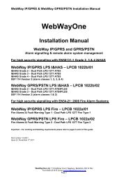
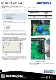
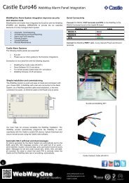
1. Unit <strong>IP</strong> Address<br />
5<br />
2. Default Gateway/Router – Local network <strong>IP</strong> address MCT 2<br />
3. Subnet Mask<br />
xxx.xxx.xxx.xxx<br />
4. <strong>IP</strong> Port - 50561<br />
5. ARC Network Facing <strong>IP</strong> Addresses<br />
MCT<br />
MCT<br />
Monitoring<br />
Centre<br />
Transceiver
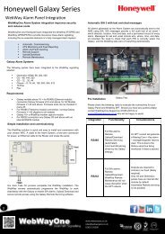
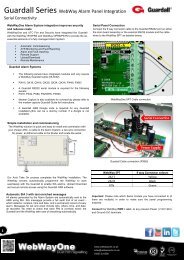
<strong>WebWay</strong> <strong>IP</strong>/<strong>GPRS</strong> SPT (Mk IV)
LED Status Indictors<br />
PNL – Panel Interface Status<br />
EXT – Not used<br />
ATS – Active Alarm Transmission Paths (ATPs)<br />
MSG – Message Queue/Delivery Status<br />
SMG – Commission Status
Power<br />
12 or 24 Volts DC<br />
Mains<br />
Fail<br />
Tamper<br />
Interfaces<br />
Battery<br />
Fail<br />
TTL<br />
RX -TX<br />
RS485<br />
RX -TX<br />
RS232<br />
RX -TX<br />
Ground
Dial Capture Module (DCM)<br />
Panels that are not supported on a serial bus may be connected<br />
Via an on-board dialer to the DCM.<br />
Important note!<br />
The SPT must be powered down before the DCM is fitted.
Hard wired Inputs 1-8 configured as ‘end of line’ (EOL)<br />
Alarm state 10k +/- 5%<br />
Restore state 14k7 +/- 5%<br />
Open circuit<br />
Loop > 100k ohms<br />
Short circuit<br />
Loop < 5 ohms<br />
Tamper conditions - Loop between > 5 ohms & < 10k ohms -5%<br />
- Loop between > 10k ohms + 5% & < 14k7 ohms -5%<br />
- Loop between > 14k7 ohms + 5% & < 100k ohms<br />
If required the alarm <strong>and</strong> restore conditions may be reversed in the SPT configuration<br />
Hard wired Inputs 1-16 configured as simple high inputs<br />
Input threshold high to low 2.0V DC (maximum Input voltage: 30V DC)<br />
If required the alarm <strong>and</strong> restore conditions may be reversed in the SPT configuration<br />
Hard wired Inputs configured as simple low inputs<br />
Input threshold low to high 4.0V DC (maximum Input voltage: 30V DC)<br />
If required the alarm <strong>and</strong> restore conditions may be reversed in the SPT configuration<br />
Pin Profile<br />
This is the default <strong>WebWay</strong>One pin configuration is you require a different set up, please contact us. Bespoke Pin profiles will take 24 hours to create.<br />
Pin Alarm Code Alarm Text Restore Code Restore Text Alarm (Pin) Number Pin Sense<br />
1 FA Fire Alarm FR Fire Restore 8001 Negative<br />
2 PA Panic Alarm PR Panic Alarm Restore 8002 Negative<br />
3 BA Intruder Alarm BR Intruder Restore 8003 Negative<br />
4 CL Close OP Open 8004 Negative<br />
5 BB Burglar Bypass BU Burglar Unbypass 8005 Negative<br />
6 IA Equipment Fault IR Equipment Fault Restore 8006 Negative<br />
7 BV Intruder Confirm BW Intruder Confirm Restore 8007 Negative<br />
8 LB Engineer Mode LX Engineer Exit 8008 Negative<br />
9 KA Freezer Alarm KR Freezer Restore 8009 Negative<br />
10 FT Fire Fault FV Fire Fault Restore 8010 Negative<br />
11 TA Lid Tamper Alarm TR Lid Tamper Restore 8011 Negative<br />
12 AT Mains Fail AR Mains Restore 8012 Negative<br />
13 YT Battery Fail YR Battery Restore 8013 Negative<br />
14 TA General Tamper Alarm TR General Tamper Restore 8014 Negative
Site <strong>Commissioning</strong><br />
Auto-Take-on Process<br />
This process associates that SPT Serial Number (found on the Ethernet port socket) with<br />
The Site ID/Account No/Chip Number allocated by the ARC within the MCT. This is known as Take-On.<br />
Once the association has been made, the SPT is downloaded with its site specific information which<br />
Includes any fixed <strong>IP</strong> address details, panel types (for serial connection to the panel) <strong>and</strong> reporting times.
Establishing Communications to the ARC – <strong>Commissioning</strong><br />
!!!You will need to know the Site ID/Chip number of the site BEFORE you can commission the<br />
unit!!!<br />
Auto-Take-On Process<br />
1. Locate Unit in Power Supply/Alarm Panel – (12V or 24V operation)<br />
2. Connect unit to network <strong>and</strong> power-up<br />
3. Enter Site ID/Chip number via the 7 segment display<br />
4. Re-boot the communicator<br />
Processes 1 & 2<br />
• Securely fasten the unit within the PSU or Alarm Panel. Ensure that the unit cannot make contact<br />
with any metal surfaces that may cause an electrical short<br />
• Connect Ethernet Cable from unit to the RJ45 patch port.<br />
• Ensure Aerial is connected to SPT unit.<br />
• Power up unit – 12V supply connecting to IN+ <strong>and</strong> IN –<br />
• Unit will begin start-up sequence
Processes 3 & 4 - Commission<br />
You will now need to input the Site ID/Chip number using the ABC buttons <strong>and</strong> the 7 segment display<br />
•Tap Button A until menu d is displayed on the 7 segment display<br />
•Hold down the C button until _ is displayed. This menu is now in Entry mode.<br />
•Using the A (scroll down) or B (scroll up) button find the first digit of the Site ID/Chip number<br />
•Tap the C button to enter the digit. The 7 segmenent display will return to _.<br />
•Continue to enter the remainder of the Site ID using the A, B, C buttons<br />
•Once you have entered the Site ID/Chip Number tap the C button a second time. The 7 segment<br />
display will cycle <strong>and</strong> return to menu d.<br />
•Now Tap the reset button located just above the 7 segment display.<br />
The SPT will now re-boot <strong>and</strong> establish communication to the ARC.<br />
During this process the <strong>IP</strong> addresses relating to the installation will be downloaded to the unit <strong>and</strong><br />
communication will be established to the ARC via the <strong>IP</strong> path. This information can be viewed <strong>and</strong><br />
confirmed via the 7 segment display using the A & B button to access the relevant menu, <strong>and</strong> tapping<br />
the C button to display the setting:-<br />
Menu 1 – Unit <strong>IP</strong> address<br />
Menu 5 – Local <strong>IP</strong> address of the Router/Default Gateway<br />
Menu 6 – Subnet Mask<br />
n.b. In some instances data corruption due to the download via <strong>GPRS</strong> may mean that the <strong>IP</strong><br />
addresses are not fully configured within the unit. A second manual re-boot may be required if an <strong>IP</strong><br />
path is not established immediately.
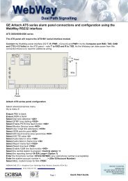
Connection of the Intruder System (IAHS)<br />
Where possible the SPT should be connected to one of the following, listed in order of preference:-<br />
1 – Serial/Data bus of the IAHS<br />
All SPT PCBs are shipped with the panel interface set to RS485.<br />
2 – Connecting an existing IAHS digi/modem to the modem capture PCB of the SPT<br />
When attaching a SPT Modem Capture PCB the SPT Broadway MUST be powered down.<br />
Ensure that the OSC jumper is set to the 66Mhz setting<br />
3 – Hard wire outputs<br />
-Default BIAS setting is HIGH = 7 volts on pin with nothing connected. Pull low to trigger event<br />
-A common negative/positive will be required<br />
-Be prepared to install a Relay<br />
-Support will not create specific profiles for individual accounts. If you cannot change the<br />
Bias via the panel – contact panel manufacturer support.<br />
Panel Types <strong>and</strong> connection<br />
Galaxy – RS485 – Access Menu 56 <strong>and</strong> configure as an Ethernet Module.<br />
Aritech (Cd & ATS) – Modem Capture PCB<br />
For more detail see accompanying manuals <strong>and</strong> installation guides.<br />
Once connected, test alarms through to the Central Station.
<strong>GPRS</strong> - Unit Location<br />
Reliable <strong>GPRS</strong> reception may be affected by many factors:-<br />
•Service Provider Coverage<br />
•Location within the protected premises <strong>and</strong> positioning of the aerial<br />
(i.e. Not in a basement! – Avoid Wooden Cupboards)<br />
•Building construction – metal clad etc.<br />
•Interference from other radio devices<br />
Do’s<br />
•Look for a suitable location for the unit<br />
•Uncoil the aerial cable.<br />
•Where HG antennas are used, external location is possible. Aerials are <strong>IP</strong> rated. NSI states<br />
that external location of aerials is acceptable for dual path systems.<br />
Don’ts<br />
•Coil the aerial inside the panel/ PSU enclosure<br />
•Coil aerial cable in tight loop<br />
•Install in a position where radio reception may be impaired. Cupboards – Basements.<br />
•Attach aerial to steel surfaces or near electrical conduits<br />
•Install near “other” radio devices<br />
•Cut HG antenna cables to reduce length<br />
•Increase HG/Disc antenna cable lengths – Max Cable Run Disc = 0.5M; HG = 15M
<strong>IP</strong> Communication cannot be established<br />
Check SP Good LED behind Ethernet Socket – Red = Not connected to Local Area Network (LAN)<br />
Check cable patching<br />
Check Cable<br />
Make a note of the <strong>IP</strong> addresses configured within the unit using the A, B & C buttons in conjunction<br />
with the 7 segment display. Access menus:-<br />
1 – Unit <strong>IP</strong> Address<br />
5 – Router/Default Gateway<br />
6 – Subnet Mask<br />
Re-boot the SPT<br />
Carry out a Ping test on the local router <strong>and</strong> note the result:-<br />
Put D<strong>IP</strong> Switch 3 to the ON position<br />
Tap Button A<br />
Unit will read out: -<br />
Ping Good – <strong>IP</strong> addresses are correct, local firewall or corporate firewall is blocking traffic to the ARC<br />
Ping Fail – Router cannot be reached. <strong>IP</strong> addresses may be incorrect, unit may not be on the correct<br />
LAN<br />
No ETH – Unit cannot detect a LAN – cable unplugged.<br />
Contact Support