Modeling of Biogas Reactors
Modeling of Biogas Reactors
Modeling of Biogas Reactors

You also want an ePaper? Increase the reach of your titles
YUMPU automatically turns print PDFs into web optimized ePapers that Google loves.
186 6 <strong>Modeling</strong> <strong>of</strong> <strong>Biogas</strong> <strong>Reactors</strong><br />
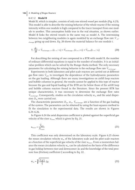
6.4.1.2 Model B<br />
Model B, which is simpler, consists <strong>of</strong> only one stirred vessel per module (Fig. 6.23).<br />
This model is able to describe the mixing behavior <strong>of</strong> the whole reactor if the mixing<br />
intensity within one module is high compared to the tracer transport from one module<br />
to another. This assumption holds true in the real situation, as shown earlier.<br />
Model B links the stirred vessels in the same way as model A. The intermixing<br />
between two neighboring modules is again modeled by an exchange flow rate V · exchange<br />
going up and down. Eq. 20 shows the material balance for one module i.<br />
dc i<br />
Vi = V · exchange,i–1 (ci –1–c i) + V · exchange,i (cic1–ci) + V · feed(ci –1–c i) (20)<br />
dt<br />
For describing the mixing <strong>of</strong> one compound in a BTR with model B, the number<br />
<strong>of</strong> ordinary differential equations is equal to the number <strong>of</strong> modules. It is an initialvalue<br />
problem which can be solved by the Runge–Kutta method. The only necessary<br />
parameter for calculating the mixing behavior is the exchange flow rate V · exchange.<br />
Experiments in both laboratory and pilot scale reactors are carried out at different<br />
gas flow rates V · gas to investigate the dependence <strong>of</strong> the hydrodynamic parameters<br />
on the gas loading. Although there are many investigations on airlift loop reactors<br />
and bubble columns in general, the results cannot be applied to this type <strong>of</strong> reactor<br />
because the gas and liquid loading <strong>of</strong> the BTR are far below those <strong>of</strong> the airlift loop<br />
and bubble column reactors found in the literature. Since the present BTR has<br />
unique characteristics, it was necessary to determine the exchange flow rates<br />
V · exchange. Consequently, studies on the circulation velocity w m and the axial dispersion<br />
D ax were carried out.<br />
The characteristic parameters D ax, w m, V · exchange, are a function <strong>of</strong> the gas loading<br />
<strong>of</strong> the system. The parameters can be obtained by using the least-squares method to<br />
fit the simulation to the experimental data. The results are shown in Figures<br />
6.24–6.26.<br />
In Figure 6.24 the axial dispersion coefficient is plotted against the superficial gas<br />
velocity <strong>of</strong> the riser u riser which is given by Eq. 21.<br />
u riser =<br />
This coefficient was only determined on the laboratory scale. Figure 6.25 shows<br />
the mean circulation velocity w m <strong>of</strong> the laboratory scale and the pilot scale reactors<br />
as a function <strong>of</strong> the superficial gas velocity <strong>of</strong> the riser u riser, From a momentum balance<br />
the mean circulation velocity w m can be calculated on the basis <strong>of</strong> the difference<br />
in gas holdup between riser and downcomer Äå and the knowledge <strong>of</strong> the total pressure<br />
loss (friction) coefficient î according to Eq. 22.<br />
;<br />
V · gas<br />
A riser<br />
wm =<br />
2 g L<br />
Äå<br />
(22)<br />
�<br />
(21)