mechanical stability of solar cells within solar panels - Solon
mechanical stability of solar cells within solar panels - Solon
mechanical stability of solar cells within solar panels - Solon

Create successful ePaper yourself
Turn your PDF publications into a flip-book with our unique Google optimized e-Paper software.
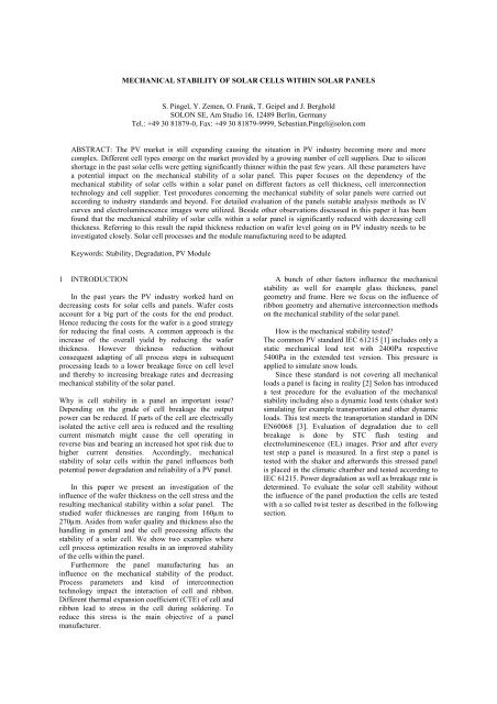
MECHANICAL STABILITY OF SOLAR CELLS WITHIN SOLAR PANELS<br />
S. Pingel, Y. Zemen, O. Frank, T. Geipel and J. Berghold<br />
SOLON SE, Am Studio 16, 12489 Berlin, Germany<br />
Tel.: +49 30 81879-0, Fax: +49 30 81879-9999, Sebastian.Pingel@solon.com<br />
ABSTRACT: The PV market is still expanding causing the situation in PV industry becoming more and more<br />
complex. Different cell types emerge on the market provided by a growing number <strong>of</strong> cell suppliers. Due to silicon<br />
shortage in the past <strong>solar</strong> <strong>cells</strong> were getting significantly thinner <strong>within</strong> the past few years. All these parameters have<br />
a potential impact on the <strong>mechanical</strong> <strong>stability</strong> <strong>of</strong> a <strong>solar</strong> panel. This paper focuses on the dependency <strong>of</strong> the<br />
<strong>mechanical</strong> <strong>stability</strong> <strong>of</strong> <strong>solar</strong> <strong>cells</strong> <strong>within</strong> a <strong>solar</strong> panel on different factors as cell thickness, cell interconnection<br />
technology and cell supplier. Test procedures concerning the <strong>mechanical</strong> <strong>stability</strong> <strong>of</strong> <strong>solar</strong> <strong>panels</strong> were carried out<br />
according to industry standards and beyond. For detailed evaluation <strong>of</strong> the <strong>panels</strong> suitable analysis methods as IV<br />
curves and electroluminescence images were utilized. Beside other observations discussed in this paper it has been<br />
found that the <strong>mechanical</strong> <strong>stability</strong> <strong>of</strong> <strong>solar</strong> <strong>cells</strong> <strong>within</strong> a <strong>solar</strong> panel is significantly reduced with decreasing cell<br />
thickness. Referring to this result the rapid thickness reduction on wafer level going on in PV industry needs to be<br />
investigated closely. Solar cell processes and the module manufacturing need to be adapted.<br />
Keywords: Stability, Degradation, PV Module<br />
1 INTRODUCTION<br />
In the past years the PV industry worked hard on<br />
decreasing costs for <strong>solar</strong> <strong>cells</strong> and <strong>panels</strong>. Wafer costs<br />
account for a big part <strong>of</strong> the costs for the end product.<br />
Hence reducing the costs for the wafer is a good strategy<br />
for reducing the final costs. A common approach is the<br />
increase <strong>of</strong> the overall yield by reducing the wafer<br />
thickness. However thickness reduction without<br />
consequent adapting <strong>of</strong> all process steps in subsequent<br />
processing leads to a lower breakage force on cell level<br />
and thereby to increasing breakage rates and decreasing<br />
<strong>mechanical</strong> <strong>stability</strong> <strong>of</strong> the <strong>solar</strong> panel.<br />
Why is cell <strong>stability</strong> in a panel an important issue?<br />
Depending on the grade <strong>of</strong> cell breakage the output<br />
power can be reduced. If parts <strong>of</strong> the cell are electrically<br />
isolated the active cell area is reduced and the resulting<br />
current mismatch might cause the cell operating in<br />
reverse bias and bearing an increased hot spot risk due to<br />
higher current densities. Accordingly, <strong>mechanical</strong><br />
<strong>stability</strong> <strong>of</strong> <strong>solar</strong> <strong>cells</strong> <strong>within</strong> the panel influences both<br />
potential power degradation and reliability <strong>of</strong> a PV panel.<br />
In this paper we present an investigation <strong>of</strong> the<br />
influence <strong>of</strong> the wafer thickness on the cell stress and the<br />
resulting <strong>mechanical</strong> <strong>stability</strong> <strong>within</strong> a <strong>solar</strong> panel. The<br />
studied wafer thicknesses are ranging from 160µm to<br />
270µm. Asides from wafer quality and thickness also the<br />
handling in general and the cell processing affects the<br />
<strong>stability</strong> <strong>of</strong> a <strong>solar</strong> cell. We show two examples where<br />
cell process optimization results in an improved <strong>stability</strong><br />
<strong>of</strong> the <strong>cells</strong> <strong>within</strong> the panel.<br />
Furthermore the panel manufacturing has an<br />
influence on the <strong>mechanical</strong> <strong>stability</strong> <strong>of</strong> the product.<br />
Process parameters and kind <strong>of</strong> interconnection<br />
technology impact the interaction <strong>of</strong> cell and ribbon.<br />
Different thermal expansion coefficient (CTE) <strong>of</strong> cell and<br />
ribbon lead to stress in the cell during soldering. To<br />
reduce this stress is the main objective <strong>of</strong> a panel<br />
manufacturer.<br />
A bunch <strong>of</strong> other factors influence the <strong>mechanical</strong><br />
<strong>stability</strong> as well for example glass thickness, panel<br />
geometry and frame. Here we focus on the influence <strong>of</strong><br />
ribbon geometry and alternative interconnection methods<br />
on the <strong>mechanical</strong> <strong>stability</strong> <strong>of</strong> the <strong>solar</strong> panel.<br />
How is the <strong>mechanical</strong> <strong>stability</strong> tested?<br />
The common PV standard IEC 61215 [1] includes only a<br />
static <strong>mechanical</strong> load test with 2400Pa respective<br />
5400Pa in the extended test version. This pressure is<br />
applied to simulate snow loads.<br />
Since these standard is not covering all <strong>mechanical</strong><br />
loads a panel is facing in reality [2] <strong>Solon</strong> has introduced<br />
a test procedure for the evaluation <strong>of</strong> the <strong>mechanical</strong><br />
<strong>stability</strong> including also a dynamic load tests (shaker test)<br />
simulating for example transportation and other dynamic<br />
loads. This test meets the transportation standard in DIN<br />
EN60068 [3]. Evaluation <strong>of</strong> degradation due to cell<br />
breakage is done by STC flash testing and<br />
electroluminescence (EL) images. Prior and after every<br />
test step a panel is measured. In a first step a panel is<br />
tested with the shaker and afterwards this stressed panel<br />
is placed in the climatic chamber and tested according to<br />
IEC 61215. Power degradation as well as breakage rate is<br />
determined. To evaluate the <strong>solar</strong> cell <strong>stability</strong> without<br />
the influence <strong>of</strong> the panel production the <strong>cells</strong> are tested<br />
with a so called twist tester as described in the following<br />
section.
2 EXPERIMENTAL<br />
2.1 Twist test for investigating on cell level<br />
To evaluate <strong>mechanical</strong> <strong>stability</strong> <strong>of</strong> <strong>solar</strong> <strong>cells</strong><br />
without the influence <strong>of</strong> the interconnection and<br />
lamination processes an <strong>of</strong>fline twist tester is used.<br />
Details <strong>of</strong> this test are described in [4]; a picture <strong>of</strong><br />
replication is shown in fig. 1. The <strong>solar</strong> cell is supported<br />
in two edges along the diagonal. An increasing force is<br />
applied on the two other edges until the cell breaks.<br />
Maximum bending and breakage force are measured.<br />
Figure 1: Twist tester setup.<br />
2.2 Dynamic load test for <strong>panels</strong><br />
To simulate <strong>mechanical</strong> stress that <strong>panels</strong> may<br />
experience during their lifetime a so called shaker is an<br />
appropriate setup. The excitation <strong>of</strong> the specimen is in a<br />
broad frequency range where frequencies occur<br />
randomly. The shaker utilized at <strong>Solon</strong>, see fig. 2, from<br />
LDS is capable <strong>of</strong> simulating transportation in the broad<br />
frequency band from 5 to 500Hz. The resonance<br />
frequency <strong>of</strong> a panel is in the range <strong>of</strong> 10-15Hz which is<br />
part <strong>of</strong> the excitation spectrum. Testing is carried out<br />
according to the transportation standard part <strong>of</strong><br />
DIN EN60068.<br />
Figure 2: Shaker setup.<br />
Other established <strong>mechanical</strong> load tests that are<br />
named in common PV standards IEC 61215 usually work<br />
with static loads (2400Pa/5400Pa). Static or single<br />
frequency loads do not cover naturally occurring multi<br />
frequency loads from wind or transportation. Material<br />
fatigue can be tested in an appropriate time if a load is<br />
applied with a higher frequency, as done with the shaker.<br />
2.3 Evaluation <strong>of</strong> the <strong>mechanical</strong> damage<br />
In this study all <strong>panels</strong> are evaluated with an<br />
electroluminescence (EL) image taken with a high<br />
resolution CCD camera. To weight power loss due to<br />
<strong>mechanical</strong> stress the power <strong>of</strong> the <strong>panels</strong> is measured<br />
before and after each test with a common flasher.<br />
Concerning power degradation the grade <strong>of</strong> cell<br />
breakage can be investigated with the EL method: Two<br />
extremes can be distinguished: (a) micro cracks that do<br />
not change the performance <strong>of</strong> a cell and (b) further<br />
propagated and expanded cracks that lead to isolation <strong>of</strong><br />
parts <strong>of</strong> a single cell. This isolation creates loss <strong>of</strong> power<br />
due to lower cell short circuit current or an increase in<br />
series resistance. During <strong>mechanical</strong> or thermal stress a<br />
crack <strong>of</strong> type (a) can propagate to type (b) as shown in<br />
fig. 3.<br />
Figure 3: EL image <strong>of</strong> a cell initial (left) after shaker<br />
(middle) and after TC400 (right). Clearly visible is the<br />
origin and evolution <strong>of</strong> cracks because <strong>of</strong> <strong>mechanical</strong> and<br />
further growth due to thermal stress.<br />
The breakage rate <strong>of</strong> a panel is determined by simply<br />
counting the number <strong>of</strong> <strong>cells</strong> showing cracks or breakage<br />
and dividing this by the number <strong>of</strong> <strong>cells</strong> in the panel. This<br />
rate neglects classification <strong>of</strong> breakage but the degree <strong>of</strong><br />
damage is indicated by the power degradation.<br />
3 EXPERIMENTAL RESULTS<br />
3.1 Wafer thickness dependence<br />
Cells made from acidic (160, 180, 200 and 220µm)<br />
and alkaline textured (270µm) wafers by one <strong>of</strong> <strong>Solon</strong>’s<br />
suppliers were used to build framed 60 cell <strong>panels</strong>. Every<br />
group <strong>of</strong> <strong>panels</strong> (4-8 <strong>panels</strong> per group) was tested with<br />
the shaker. For each group <strong>of</strong> <strong>panels</strong> and every cell<br />
position in the panel the average breakage rate is shown<br />
in fig. 4. Cells located closer to the aluminum frame<br />
show less damage. Clearly visible is the large damage for<br />
160 and 180µm after the shaker test.<br />
Figure 4: Average spatially resolved breakage rate for 60<br />
<strong>cells</strong> <strong>panels</strong> made from <strong>cells</strong> with varying thicknesses<br />
after shaker test.
Aside from counting broken <strong>cells</strong> the power <strong>of</strong> the <strong>panels</strong><br />
was re-measured after the test. Results <strong>of</strong> breakage rate<br />
and power degradation are shown in Fig. 5.<br />
Figure 5: Average breakage rate depending on wafer<br />
thickness before and after shaker test. Values for power<br />
degradation are also noted.<br />
Both the number <strong>of</strong> broken <strong>cells</strong> and the power loss<br />
clearly increase with decreasing wafer thickness. The<br />
power loss in the field can be higher, because only<br />
<strong>mechanical</strong> stress was applied in this experiment.<br />
Deviations may be explained on cell side by large<br />
tolerances in wafer thickness (usually specified are<br />
variations up to 20%) and quality but also the cell process<br />
has a large influence on the <strong>mechanical</strong> strength as will<br />
be shown below. The impact <strong>of</strong> wafer thickness and<br />
manufacturing process effects the cell <strong>stability</strong> as<br />
investigated in [4]. Especially the texturization as well as<br />
printing and firing <strong>of</strong> the Al paste play an important role.<br />
Soldering and lamination process have a large influence<br />
on the <strong>stability</strong> <strong>of</strong> the cell in the panel compound.<br />
As shown here thinner <strong>cells</strong> are more likely to break<br />
although they are more flexible in the twist test. But as<br />
will be shown in the next sections there is room for<br />
improvement on cell and panel level.<br />
3.3 Influence <strong>of</strong> cell process on <strong>stability</strong><br />
The shaker test became an essential part <strong>of</strong> the cell<br />
release process. For example first tests with one <strong>of</strong> our<br />
mono suppliers using 200µm wafers showed a breakage<br />
rate <strong>of</strong> up to 60% (fig. 6). This rate is not acceptable<br />
concerning long term reliability in the field.<br />
This experiment shows that not alone thickness<br />
affects the <strong>mechanical</strong> <strong>stability</strong> <strong>of</strong> a cell but the whole<br />
cell process has a large impact.<br />
With these results the cell supplier analyzed their cell<br />
process concerning <strong>mechanical</strong> stress and optimized the<br />
process. New <strong>cells</strong> were delivered and tested again. The<br />
breakage rate dropped to below 10%. See figures 6 and 7<br />
before and after process optimization.<br />
Figure 6: Panel EL image before (top) and after (bottom)<br />
<strong>mechanical</strong> load test before optimization <strong>of</strong> the mono<br />
crystalline <strong>cells</strong>.<br />
Figure 7: Panel EL image before (top) and after (bottom)<br />
<strong>mechanical</strong> load test <strong>of</strong> the optimized mono <strong>cells</strong>.<br />
Optimized and not optimized <strong>cells</strong> from this supplier<br />
were compared with the twist test. A significant increase<br />
in breakage force <strong>of</strong> about 7% was found. The internal<br />
stress or pre damage <strong>of</strong> the cell must have been reduced.<br />
This indication supports the results <strong>of</strong> the <strong>mechanical</strong><br />
load test on panel level. Another important result <strong>of</strong> this<br />
investigation: simply using thick wafers or <strong>cells</strong> for<br />
<strong>panels</strong> is no good assurance for good reliability.
As shown in the section about the thickness dependence,<br />
thin <strong>cells</strong> are more likely to break but there is the<br />
potential to reduce overall costs. Nowadays panel<br />
manufacturer are facing <strong>solar</strong> cell thickness as low as<br />
160µm. Initial tests at <strong>Solon</strong> with these <strong>cells</strong> showed low<br />
<strong>stability</strong> and a breakage rate <strong>of</strong> almost 40% and a power<br />
degradation <strong>of</strong> 1.9% after <strong>mechanical</strong> load and TC200,<br />
see fig. 9.<br />
Figure 8: EL image <strong>of</strong> panel with 160µm <strong>cells</strong> (II run)<br />
before test sequence (top) and after shaker and TC400<br />
(bottom).<br />
After several test runs and significant adaption <strong>within</strong><br />
the cell process later batches <strong>of</strong> 160µm test <strong>cells</strong> showed<br />
promising results. Further process optimizations lead to<br />
stable power during the shaker test and low degradation<br />
in thermal cycling (TC) with 200 cycles (
Figure 11: Mono and multi crystalline cell supplier<br />
comparison in breakage rate after shaker test.<br />
The power degradation in the supplier comparison<br />
was always below 2% after shaker test and the maximum<br />
degradation found after the following TC200 was 2.5%<br />
compared to the initial power.<br />
3.5 Ribbon thickness variation and alternative<br />
interconnection technique<br />
During the soldering process stress is introduced in<br />
the cell because high temperature is needed to form a<br />
stable electric contact between busbar and ribbon. Solar<br />
cell and ribbon have different CTEs and thereby during<br />
the cool down <strong>of</strong> the string the cell gets stressed.<br />
One way to reduce this stress is to solder at lower<br />
temperatures while good adhesion must be guaranteed<br />
another way is to use a more flexible ribbon. Thinner<br />
ribbons reduce the stress introduced in the cell as well.<br />
Concerning power degradation and influence on the<br />
<strong>mechanical</strong> <strong>stability</strong> different ribbon thicknesses and<br />
alternative interconnection techniques were compared.<br />
Besides conventional soldering <strong>mechanical</strong> clamping and<br />
gluing with electrical conductive adhesive (ECA) was<br />
investigated. The results <strong>of</strong> power measurement and<br />
breakage rate are shown in fig. 12.<br />
Figure 12: Breakage rate <strong>of</strong> two <strong>panels</strong> soldered with<br />
different ribbon thicknesses (blue and orange) and two<br />
<strong>panels</strong> made with non soldering techniques - <strong>mechanical</strong><br />
clamping (green) and ECA (black). Above the data points<br />
is noted the relative power degradation.<br />
In the case <strong>of</strong> <strong>mechanical</strong> clamping all <strong>cells</strong> survive the<br />
<strong>mechanical</strong> load test without any breakage. Compared to<br />
this glued and soldered <strong>cells</strong> show higher breakage rates<br />
<strong>of</strong> ~2% for ECA and the thinner ribbon and 15% for the<br />
thicker ribbon after shaker test. After the following<br />
TC200 breakage rate rose a bit for the soldered <strong>panels</strong>.<br />
Looking at the power degradation the impression is<br />
contrary. Soldering shows only negligible power<br />
degradation while ECA has a little higher as noted in<br />
fig. 12. The clamped panel degrades by extreme 6.8%<br />
because the electric contact is not stable during thermal<br />
expansion and contraction. Table I summarizes the<br />
results <strong>of</strong> this investigation.<br />
Table I: Comparison <strong>of</strong> interconnection techniques<br />
Ribbon<br />
Interconnection<br />
Clamped Soldered Glued<br />
Long term<br />
<strong>stability</strong><br />
- + +<br />
Mechanical<br />
<strong>stability</strong><br />
+ 0 +<br />
This experiments shows that soldering does induce stress<br />
to the cell which increases if thicker ribbons are used. In<br />
terms <strong>of</strong> long term reliability soldering is more stable<br />
than clamping as interconnection technique. The use <strong>of</strong><br />
ECA could be an interesting compromise between higher<br />
power degradation compared to soldering but with less<br />
<strong>mechanical</strong> stress. Ribbon thickness can be adapted to<br />
reduce the stress introduced in <strong>cells</strong> during soldering. In<br />
the end this is a question <strong>of</strong> minimizing the overall costs<br />
keeping in mind the higher encapsulation losses for<br />
thinner ribbons.<br />
4 CONCLUSION<br />
Wafer thickness reduction leads to higher sensitivity<br />
<strong>of</strong> the <strong>solar</strong> cell to <strong>mechanical</strong> loads. For further<br />
decreasing <strong>of</strong> wafer thickness all following process steps<br />
<strong>within</strong> the value chain have to be carefully adapted in the<br />
cell production as well as the panel production. As shown<br />
for <strong>cells</strong> made from 160µm wafers it is possible to build<br />
stable <strong>panels</strong> provided the internal stress is reduced on<br />
cell and panel level. Therefore all processes <strong>within</strong> the<br />
value chain need to be optimized concerning <strong>mechanical</strong><br />
<strong>stability</strong>. On panel production side it was shown that the<br />
stress introduced by the soldering process can be<br />
significantly reduced by the usage <strong>of</strong> optimized ribbon or<br />
alternative interconnection techniques like ECA.<br />
All these process optimizations for <strong>solar</strong> <strong>cells</strong> are the<br />
key for panel reliability and a lifetime <strong>of</strong> 25+ years.<br />
5 REFERENCES<br />
[1] IEC 61215 “Crystalline Silicon Terrestrial<br />
Photovoltaic Modules – Design Qualification and<br />
Type Approval” edition 2 (2005)<br />
[2] Wohlgemuth, J. H., "The effect <strong>of</strong> cell thickness on<br />
module reliability“33rd IEEE PVSC (2008)<br />
[3] IEC 60068-2-64 “Environmental testing - Part 2-64:<br />
Tests - Test Fh: Vibration, broadband random and<br />
guidance” edition 2 (2008)<br />
[4] Schneider, A., PHD Thesis, University <strong>of</strong> Konstanz<br />
(2004)