HD Color Video Camera â EVI-H100S/H100V A - Full Compass
HD Color Video Camera â EVI-H100S/H100V A - Full Compass
HD Color Video Camera â EVI-H100S/H100V A - Full Compass

Create successful ePaper yourself
Turn your PDF publications into a flip-book with our unique Google optimized e-Paper software.
A-E4U-100-11(1)<br />
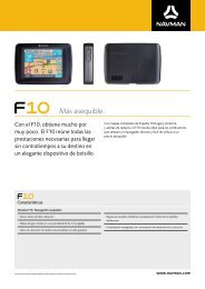
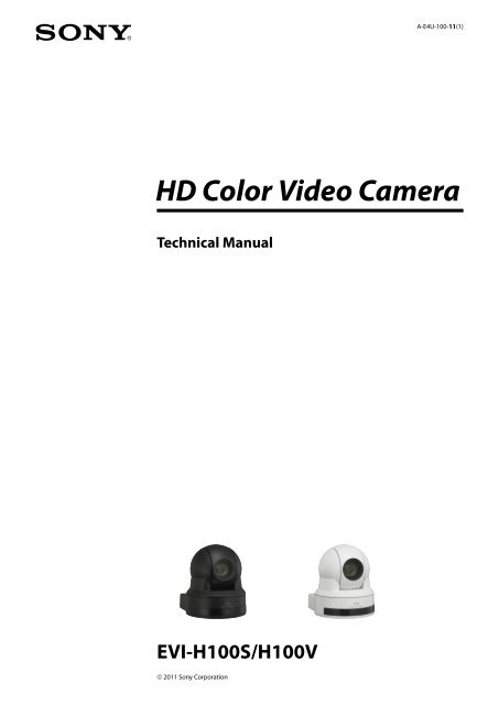
<strong>HD</strong> <strong>Color</strong> <strong>Video</strong> <strong>Camera</strong><br />
Technical Manual<br />
<strong>EVI</strong>-<strong>H100S</strong>/<strong>H100V</strong><br />
© 2011 Sony Corporation
Table of Contents<br />
Features............................................................................. 3<br />
Connection........................................................................ 4<br />
Locations of Controls........................................................ 6<br />
Basic Functions................................................................10<br />
Overview of Functions.................................................................. 10<br />
Initial Settings and Position Preset........................................... 16<br />
Mode Condition............................................................................... 18<br />
Command List..................................................................23<br />
VISCA RS-232C Commands......................................................... 23<br />
<strong>EVI</strong>-<strong>H100S</strong>/<strong>H100V</strong> Commands................................................... 31<br />
D70 Mode.........................................................................47<br />
Overview............................................................................................ 47<br />
Switching the Mode....................................................................... 47<br />
Accepting or Sending Back Commands................................. 48<br />
Translating Parameters................................................................. 49<br />
Specifications..................................................................51<br />
Precautions......................................................................54
Features<br />
The 1/2.8 type Exmor CMOS camera (utilising<br />
approximately 2 million valid pixels) allows for highdefinition<br />
shooting with superior picture quality.<br />
The camera is equipped with a bright, F1.6 zoom lens<br />
with 20× optical zoom.<br />
By adopting its wide and dynamic range functions,<br />
you can see the optimised shooting image which<br />
incorporates bright and dark subjects at the same<br />
time.<br />
The camera has a variety of <strong>HD</strong> video format choices<br />
and digital and analogue interface connectors. The<br />
<strong>EVI</strong>-<strong>H100S</strong> camera has <strong>HD</strong>-SDI (High Definition-<br />
Serial Digital Interface) output, suitable for longdistance<br />
transmission. The <strong>EVI</strong>-<strong>H100V</strong> camera has a<br />
DVI-I (VIDEO OUT) connector supporting both<br />
digital and analogue output.<br />
The camera can be used for NTSC and PAL output in<br />
letter box size (<strong>EVI</strong>-<strong>H100S</strong>).<br />
Adopts the industry standard RS-232C interface of<br />
VISCA camera protocol in external communication.<br />
It is possible to operate from long distances by using<br />
both RS-232C and RS-422.<br />
You can install the camera on ceilings due to the<br />
functions of high-speed and wide range pan/tilt<br />
action and vertical image flip.<br />
You can use the infrared remote commander to set<br />
the camera and also to select panning, tilting and<br />
zooming from the setting menu.<br />
You can store up to 6 kinds of camera direction and<br />
camera status into the camera.
Connection<br />
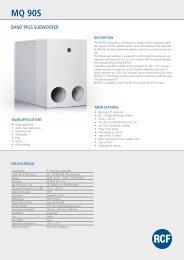
<strong>EVI</strong>-<strong>H100S</strong><br />
<strong>Video</strong> cable<br />
(not supplied)<br />
to <strong>Video</strong><br />
input<br />
to VIDEO<br />
Cable with BNC connector<br />
(not supplied)<br />
to <strong>HD</strong>-SDI<br />
to <strong>HD</strong>-SDI input<br />
connector<br />
VISCA cable (not supplied) 1)<br />
to VISCA IN<br />
to RS-232C<br />
to VISCA OUT<br />
to VISCA RS-422 2)<br />
To VISCA IN of other<br />
<strong>EVI</strong>-<strong>H100S</strong>/<strong>H100V</strong><br />
(when connecting<br />
to more than one<br />
camera)<br />
Computer, video<br />
monitor, <strong>HD</strong> video<br />
monitor, VCR or <strong>HD</strong><br />
CAM VTR with a video<br />
input jack, etc.<br />
AC power adaptor (supplied)<br />
to AC outlet<br />
to DC 12V<br />
Power cord (supplied)<br />
1) When the camera is connected to a computer with a VISCA cable (cross type, RS-232C), you can operate the<br />
camera with the computer. To obtain a cable, consult the dealer where you bought your camera.<br />
2) For details on how to connect using VISCA RS-422, see page 28.<br />
(Continued)
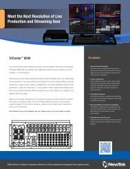
<strong>EVI</strong>-<strong>H100V</strong><br />
DVI to<br />
component<br />
adapter cable<br />
(not supplied)<br />
to component<br />
input<br />
connector<br />
to VIDEO OUT<br />
DVI cable<br />
(not supplied)<br />
to VIDEO OUT to DVI input connector<br />
VISCA cable (not supplied) 1)<br />
to VISCA IN<br />
to RS-232C<br />
to VISCA OUT<br />
to VISCA RS-422 2)<br />
To VISCA IN of other<br />
<strong>EVI</strong>-<strong>H100S</strong>/<strong>H100V</strong><br />
(when connecting<br />
to more than one<br />
camera)<br />
Computer with serial<br />
communication<br />
interface, <strong>HD</strong> video<br />
monitor with DVI input<br />
interface, etc.<br />
AC power adaptor (supplied)<br />
to AC outlet<br />
to DC 12V<br />
Power cord (supplied)<br />
1) When the camera is connected to a computer with a VISCA cable (cross type, RS-232C), you can operate the<br />
camera with the computer. To obtain a cable, consult the dealer where you bought your camera.<br />
2) For details on how to connect using VISCA RS-422, see page 28.<br />
Notes<br />
Use only the AC power adaptor (JEITA type4)<br />
supplied with the unit. Do not use any other AC<br />
power adaptor.<br />
Polarity of the plug<br />
You have to set the video format of the signal to be<br />
output from the camera. For detailed information on<br />
how to set the video format, see “ SYSTEM<br />
SELECT switch” on page 7.<br />
Do not make VISCA RS-232C and RS-422<br />
connections at the same time, as this may cause<br />
malfunctions.
Locations of Controls<br />
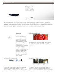
Main Unit<br />
Front<br />
<br />
Rear<br />
<br />
<strong>EVI</strong>-<strong>H100S</strong><br />
Bottom<br />
<strong>EVI</strong>-<strong>H100V</strong><br />
Lens<br />
Remote sensors<br />
POWER lamp<br />
STANDBY lamp<br />
For detailed information on LED status of the POWER lamp<br />
and STANDBY lamp, see “LED Status” on page 46.<br />
Remote sensors<br />
(Continued)
Locations of Controls<br />
IMAGE FLIP switch<br />
Flips the image upside down. Normally set this to OFF when<br />
you use the camera. When the camera is attached to the<br />
ceiling, set this to ON. Before you set the IMAGE FLIP<br />
switch, turn off the unit (or set to standby mode) and then,<br />
turn the power on by connecting the power adaptor, by<br />
VISCA control or the remote commander. When you switch<br />
this, the preset setting is returned to the initial setting.<br />
IR SELECT switch<br />
VISCA RS-422 connector<br />
SYSTEM SELECT switch<br />
This switch allows you to select the video format of the<br />
signal to be output from the VIDEO OUT connectors.<br />
Notes<br />
Be sure to set this switch before you turn on the power of the<br />
camera. You can also set this switch in the standby mode of<br />
the camera. After completing the setting, turn on the power<br />
of the camera by connecting it to an AC outlet using the<br />
supplied AC power adaptor and AC power cord, by using<br />
the VISCA command or remote commander.<br />
Be sure to use a Phillips-head screwdriver when changing<br />
the switch position. If you use a tool other than the<br />
designated screwdriver, the crossed groove may be damaged.<br />
This camera does not include a function that automatically<br />
selects video output signals based on the DVI monitor’s<br />
resolution. Be sure to configure settings based on the<br />
monitor manually. (<strong>EVI</strong>-<strong>H100V</strong>)<br />
<strong>HD</strong>TV video signal outputs display without distortion on<br />
monitors with 16:9 aspect ratios.<br />
Switch<br />
position <strong>Video</strong> format <strong>EVI</strong>-<strong>H100S</strong><br />
support<br />
1080i/<br />
0<br />
Yes<br />
59.94 (29.97PsF)<br />
<strong>EVI</strong>-<strong>H100V</strong><br />
support<br />
1 1080p/29.97 Yes Yes 59.94 Hz<br />
2 720p/59.94 Yes Yes system<br />
3 720p/29.97 Yes Yes<br />
4 NTSC (LB) Yes (SD OUT) No<br />
5 No output — — —<br />
6 No output — — —<br />
7 VISCA Control Yes Yes —<br />
8 1080i/50 (25PsF) Yes Yes<br />
9 720p/50 Yes Yes<br />
50 Hz<br />
A 720p/25 Yes Yes<br />
system<br />
B 1080i/50 Yes Yes<br />
C PAL (LB) Yes (SD OUT) No<br />
D No output — — —<br />
E No output — — —<br />
F No output — — —<br />
Yes: Outputs the image signal.<br />
No: Does not output the image signal<br />
LB: Abbreviation of LETTER BOX. A 4:3 aspect ratio<br />
video signal converted from 16:9 is output with a blank<br />
area (no signal, black) top and bottom to display the<br />
image on a 4:3 aspect ratio monitor without distortion.<br />
Notes<br />
If the switch position is set to “no output,” the<br />
POWER lamp and STANDBY lamp will both remain<br />
lit. In such cases, control via the remote commander<br />
and VISCA commands is disabled.<br />
The VISCA CONTROL switch position allows you to<br />
configure the video format via external<br />
communication. Note that your configured video<br />
format will be activated only after restarting the<br />
camera. For details on the video output format<br />
settings command, see page 33.<br />
Yes<br />
SD OUT VIDEO connector<br />
<strong>HD</strong> OUT <strong>HD</strong>-SDI connector (<strong>EVI</strong>-<strong>H100S</strong>), VIDEO OUT<br />
connector (<strong>EVI</strong>-<strong>H100V</strong>)<br />
PLUG & PLAY<br />
TMDS<br />
ANALOG<br />
Set this arrow to the<br />
desired video format.
Locations of Controls<br />
Pin No. Function<br />
1 Data_2-<br />
2 Data_2+<br />
3 Shield (2, 4)<br />
4 No connection<br />
5 No connection<br />
6 No connection<br />
7 No connection<br />
8 Analog Vertical Sync<br />
9 Data_1-<br />
10 Data_1+<br />
11 Shield (1, 3)<br />
12 No connection<br />
13 No connection<br />
14 Power_+5 V<br />
15 GND<br />
16 Hot Plug<br />
17 Data_0-<br />
18 Data_0+<br />
19 Shield (0, 5)<br />
20 No connection<br />
21 No connection<br />
22 Shield Clock<br />
23 Clock+<br />
24 Clock-<br />
C1 Analog Pr<br />
C2 Analog Y<br />
C3 Analog Pb<br />
C4 Analog Horizontal Sync<br />
C5 Analog GND<br />
RS-232C/RS-422 select switch<br />
Set to ON to operate colour video camera using the<br />
VISCA command via the RS-422 interface. To change<br />
the mode, turn off the camera (not including standby<br />
mode) first, set the switch and then turn on the camera<br />
again. The mode cannot be switched while the camera is<br />
turned on.<br />
Baud rate select switch<br />
Set to ON for 38,400 bps or OFF for 9,600 bps. To<br />
change the mode, turn off the camera (not including<br />
standby mode) first, set the switch and then turn on the<br />
camera again. Mode switching is not possible while the<br />
camera is turned on.<br />
Switch 5 (Not used)<br />
Be sure to set this switch to OFF.<br />
Tripod screw hole<br />
Ceiling bracket mounting screw holes<br />
Remote Commander<br />
VISCA IN connector<br />
VISCA OUT connector<br />
DC 12V connector<br />
BOTTOM switches<br />
1<br />
2<br />
3<br />
4<br />
5<br />
D70 mode switch<br />
Set to ON to use the VISCA command for <strong>EVI</strong>-D70/<br />
D70P.<br />
IR OUT switch<br />
Set to ON to enable output of the receiver signals, which<br />
are transmitted from the infrared remote commander<br />
via the VISCA IN connector (page 27), or set it to OFF<br />
to disable the output.<br />
CAMERA SELECT buttons<br />
Press the button corresponding to the camera you want to<br />
operate with the Remote Commander.<br />
The camera number can be set using the IR SELECT switch<br />
on the rear of the camera.<br />
Note<br />
If two or more cameras are adjacent and have the same<br />
camera number, they are operated simultaneously with the<br />
same Remote Commander. When you install the cameras<br />
close to each other, set different camera numbers.<br />
For the camera number setting, see “Operating Multiple<br />
<strong>Camera</strong>s with the Remote Commander” described in the<br />
Operating Instructions supplied with the camera.
Locations of Controls<br />
FOCUS buttons<br />
Used for focus adjustment.<br />
Press the AUTO button to adjust the focus automatically. To<br />
adjust the focus manually, press the MANUAL button, and<br />
adjust it with the FAR and NEAR buttons.<br />
DATA SCREEN button<br />
Press this button to display the main menu. Press it again to<br />
turn off the menu. If you press the button when a lower-level<br />
menu is selected, the display goes back to a higher-level<br />
menu.<br />
Note<br />
Pan/tilt operations are disabled when the menu is displayed.<br />
PAN-TILT buttons<br />
Press the arrow buttons to perform panning and tilting.<br />
Press the HOME button to face the camera back to the front.<br />
When the menu is displayed, use or to select the menu<br />
items and or to change the set values. The selected<br />
setting menu is displayed, by pressing the HOME button<br />
when the main menu is displayed.<br />
The Pan/tilt speed will slow down when the camera is<br />
zoomed, in order to allow precise positioning.<br />
L/R DIRECTION SET button<br />
Hold down this button and press the REV button to change<br />
the direction of the camera movement opposite to that<br />
indicated by the arrow of the / buttons.<br />
To reset the direction of the camera movement, press the<br />
STD button while holding down this button.<br />
POWER switch<br />
Press this button to turn on/off the camera when the camera<br />
is connected to an AC outlet.<br />
BACK LIGHT button<br />
Press this button to enable the backlight compensation.<br />
Press it again to disable the backlight compensation.<br />
POSITION buttons<br />
Hold down the PRESET button and press button 1 to 6 to<br />
store the current camera direction, zooming, focus<br />
adjustment and backlight compensation in the memory of<br />
the pressed number button.<br />
To erase the memory contents, hold down the RESET<br />
button and press button 1 to 6.<br />
Note<br />
These buttons do not function when the menu is displayed.<br />
PAN-TILT RESET button<br />
Press this button to reset the pan/tilt position.<br />
ZOOM buttons<br />
Use the SLOW button to zoom slowly, and the FAST button<br />
to zoom quickly.<br />
Press the T (telephoto) side of the button to zoom in, and<br />
the W (wide angle) side to zoom out.
Basic Functions<br />
Overview of Functions<br />
Zoom<br />
The camera employs a 20× optical zoom lens combined<br />
with a digital zoom function; this camera allows you to<br />
zoom up to 240×.<br />
Optical 20×, f = 4.7 mm to 94.0 mm (F 1.6 to F 3.5)<br />
The horizontal angle of view (1080i mode) is<br />
approximately 55.4 degrees (wide end) to 2.9 degrees<br />
(tele end).<br />
Digital Zoom enlarges the center of the subject by<br />
expanding each image in both the vertical and<br />
horizontal directions. When 240× zoom is used, the<br />
number of effective picture elements in each direction<br />
reduces to 1 /12 and the overall resolution deteriorates.<br />
You can activate the zoom in the following ways with a<br />
VISCA command.<br />
Using Standard Mode<br />
Using Variable Mode<br />
There are eight levels of zoom speed.<br />
Direct Mode<br />
Setting the zoom position enables quick movement<br />
to the designated position.<br />
Digital Zoom ON/OFF<br />
In these standard and variable Speed Modes, it is necessary to<br />
send Stop Command to stop the zoom operation.<br />
Focus<br />
Focus has the following modes, all of which can be set<br />
using VISCA Commands.<br />
Auto Focus Mode<br />
The minimum focus distance is 10 mm at the optical<br />
wide end and 800 mm at the optical tele end, and is<br />
independent of the digital zoom.<br />
The Auto Focus (AF) function automatically adjusts<br />
the focus position to maximise the high frequency<br />
content of the picture in a center measurement area,<br />
taking into consideration the high luminance and<br />
strong contrast components.<br />
- Normal AF Mode<br />
This is the normal mode for AF operations.<br />
- Interval AF Mode<br />
The mode used for AF movements carried out at<br />
particular intervals. The time intervals for AF<br />
movements and for the timing of the stops can be<br />
set in one-second increments using the Set Time<br />
Command. The initial value for both is set to five<br />
seconds.<br />
- Zoom Trigger Mode<br />
When the zoom is changed, the pre-set value<br />
(initially set at 5 seconds) becomes that for AF<br />
Mode. Then, it stops.<br />
AF sensitivity can be set to either Normal or LOW.<br />
- Normal<br />
Reaches the highest focus speed quickly. Use this<br />
when shooting a subject that moves frequently.<br />
Usually, this is the most appropriate mode.<br />
- LOW<br />
Improves the stability of the focus. When the<br />
lighting level is low, the AF function does not take<br />
effect, even though the brightness varies,<br />
contributing to a stable image.<br />
Manual Focus Mode<br />
Manual Focus has both a Standard Speed Mode and<br />
a Variable Speed Mode. Standard Speed Mode<br />
focuses at a fixed rate of speed. Variable Speed Mode<br />
has eight speed levels that can be set using a VISCA<br />
Command.<br />
10
Basic Functions<br />
In these standard and variable Speed Modes, it is necessary to send<br />
Stop Command to stop the zoom operation.<br />
One Push Trigger Mode<br />
When a Trigger Command is sent, the lens moves to<br />
adjust the focus for the subject. The focus lens then<br />
holds that position until the next Trigger Command<br />
is input.<br />
Infinity Mode<br />
The lens is forcibly moved to a position suitable for<br />
an unlimited distance.<br />
Near Limit Mode<br />
Can be set in a range from 1000 (∞) to F000<br />
(10 mm).<br />
Default setting: D000h (30 cm)<br />
White Balance<br />
White Balance has the following modes, all of which<br />
can be set using VISCA Commands.<br />
Auto White Balance<br />
This mode computes the white balance value output<br />
using color information from the entire screen. It<br />
outputs the proper value using the color temperature<br />
radiating from a black subject based on a range of<br />
values from 3,000 to 7,500 K.<br />
This mode is the default setting.<br />
Indoor<br />
3,200 K Base Mode<br />
Outdoor<br />
5,800 K Base Mode<br />
One Push WB<br />
The One Push White Balance mode is a fixed white<br />
balance mode that may be automatically readjusted<br />
only at the request of the user (One Push Trigger),<br />
assuming that a white subject, in correct lighting<br />
conditions and occupying more than 1 /2 of the<br />
image, is captured by the camera.<br />
One Push White Balance data is lost when the power<br />
is turned off. If the power is turned off, reset the One<br />
Push White Balance.<br />
Manual WB<br />
Manual control of R and B gain, 256 steps each<br />
Automatic Exposure Mode<br />
A variety of AE functions are available for optimal<br />
output of subjects in lighting conditions that range<br />
from low to high.<br />
<strong>Full</strong> Auto<br />
Exposure is adjusted automatically by gain, iris and<br />
electronic shutter setting.<br />
AE Gain Limit Setting<br />
The gain limit can be set at the <strong>Full</strong> Auto, Shutter<br />
Priority and Iris Priority in the AE mode. Use this<br />
setting when image signal-to-noise ratio is<br />
particularly important.<br />
Shutter Priority 1)<br />
Variable Shutter Speed, Auto Iris and Gain<br />
(1/1 to 1/10,000 sec., 16 high-speed shutter speeds<br />
plus 6 low-speed shutter speeds)<br />
1) Flicker can be eliminated by setting shutter to<br />
1/100s for NTSC models used in countries with a 50 Hz<br />
power supply frequency<br />
1/120s for PAL models used in countries with a 60 Hz power<br />
supply frequency<br />
Iris Priority<br />
Variable Iris (F1.6 to Close, 14 steps), Auto Gain and<br />
Shutter speed<br />
Manual<br />
Variable Shutter, Iris and Gain<br />
Bright<br />
Variable Iris and Gain (Close to F1.6, 17 steps at<br />
0 dB: F1.6, 15 steps from 0 to 28 dB)<br />
AE – Shutter priority<br />
The shutter speed can be set freely by the user to a total<br />
of 22 steps – 16 high speeds and 6 low speeds. When<br />
the slow shutter is set, the speed can be 1 /30s, 1 /15s, 1 /8s,<br />
1<br />
/4s, 1 /2s, 1 /1s. The picture output is read at a normal rate<br />
from the memory. The memory is updated at a low rate<br />
from the CMOS. AF capability is low.<br />
In high speed mode, the shutter speed can be set up to<br />
1/10,000s. The iris and gain are set automatically,<br />
according to the brightness of the subject.<br />
Data 60/30 mode 50/25 mode<br />
15 1/10000 1/10000<br />
14 1/6000 1/6000<br />
13 1/4000 1/3500<br />
12 1/3000 1/2500<br />
11 1/2000 1/1750<br />
10 1/1500 1/1250<br />
0F 1/1000 1/1000<br />
0E 1/725 1/600<br />
0D 1/500 1/425<br />
0C 1/350 1/300<br />
0B 1/250 1/215<br />
0A 1/180 1/150<br />
09 1/125 1/120<br />
08 1/100 1/100<br />
07 1/90 1/75<br />
06 1/60 1/50<br />
05 1/30 1/25<br />
04 1/15 1/12<br />
11
Basic Functions<br />
Data 60/30 mode 50/25 mode<br />
03 1/8 1/6<br />
02 1/4 1/3<br />
01 1/2 1/2<br />
00 1/1 1/1<br />
AE – Iris priority<br />
The iris can be set freely by the user to 14 steps<br />
between F1.6 and Close.<br />
The gain and shutter speed are set automatically,<br />
according to the brightness of the subject.<br />
Data Setting value Data Setting value<br />
11 F1.6 0A F5.6<br />
10 F2 09 F6.8<br />
0F F2.4 08 F8<br />
0E F2.8 07 F9.6<br />
0D F3.4 06 F11<br />
0C F4 05 F14<br />
0B F4.8 00 CLOSE<br />
AE – Manual<br />
The shutter speed (22 steps), iris (14 steps) and gain<br />
(16 steps) can be set freely by the user.<br />
AE – Bright<br />
The bright control function adjusts both gain and iris<br />
using an internal algorithm, according to a brightness<br />
level freely set by the user. Exposure is controlled by<br />
gain when dark, and by iris when bright.<br />
As both gain and iris are fixed, this mode is used when<br />
exposing at a fixed camera sensitivity. When switching<br />
from <strong>Full</strong> Auto or Shutter Priority Mode to Bright<br />
Mode, the current status will be retained for a short<br />
period of time.<br />
Only when the AE mode is set to “<strong>Full</strong> Auto” or<br />
“Shutter Priority,” can you switch it to “Bright.”<br />
IRIS<br />
Gain<br />
AGC<br />
OPEN MAX<br />
IRIS gain curve<br />
Data Iris Gain Data Iris Gain<br />
1F F1.6 28 dB 11 F1.6 0 dB<br />
1E F1.6 26 dB 10 F2 0 dB<br />
1D F1.6 24 dB 0F F2.4 0 dB<br />
1C F1.6 22 dB 0E F2.8 0 dB<br />
1B F1.6 20 dB 0D F3.4 0 dB<br />
1A F1.6 18 dB 0C F4 0 dB<br />
19 F1.6 16 dB 0B F4.8 0 dB<br />
18 F1.6 14 dB 0A F5.6 0 dB<br />
17 F1.6 12 dB 09 F6.8 0 dB<br />
16 F1.6 10 dB 08 F8 0 dB<br />
15 F1.6 8 dB 07 F9.6 0 dB<br />
14 F1.6 6 dB 06 F11 0 dB<br />
13 F1.6 4 dB 05 F14 0 dB<br />
12 F1.6 2 dB 00 CLOSE 0 dB<br />
When switching from the Shutter Priority mode to the<br />
Bright mode, the shutter speed set in the Shutter<br />
Priority mode is maintained.<br />
Exposure Compensation<br />
Exposure compensation is a function which offsets the<br />
internal reference brightness level used in the AE mode<br />
by steps of 1.5 dB.<br />
Data Step Setting value<br />
0E +7 +10.5 dB<br />
0D +6 +9 dB<br />
0C +5 +7.5 dB<br />
0B +4 +6 dB<br />
0A +3 +4.5 dB<br />
09 +2 +3 dB<br />
08 +1 +1.5 dB<br />
07 0 0 dB<br />
06 −1 −1.5 dB<br />
05 −2 −3 dB<br />
04 −3 −4.5 dB<br />
03 −4 −6 dB<br />
02 −5 −7.5 dB<br />
01 −6 −9 dB<br />
00 −7 −10.5 dB<br />
CLOSE MIN<br />
Dark<br />
Controlled<br />
by gain<br />
AGC gain curve<br />
Controlled by IRIS<br />
Bright limit controllable<br />
for this unit<br />
Bright<br />
High Resolution Mode<br />
This mode enhances edges and produces higher<br />
definition images.<br />
Aperture Control<br />
Aperture control is a function which adjusts the<br />
enhancement of the edges of objects in the picture.<br />
There are 16 levels of adjustment, starting from “no<br />
enhancement.” When shooting text, this control may<br />
help by making the text sharper.<br />
12
Basic Functions<br />
Back Light Compensation<br />
When the background of the subject is too bright, or<br />
when the subject is too dark due to shooting in the AE<br />
mode, back light compensation will make the subject<br />
appear clearer.<br />
Wide Dynamic Range Mode (WD)<br />
The Wide Dynamic Range mode is a function for<br />
dividing an image into several blocks and correcting<br />
blocked-up shadows and blown-out highlights in<br />
accordance with the intensity difference. It enables you<br />
to obtain images in which portions ranging from dark<br />
to light can be recognized, even when capturing a<br />
subject with a large intensity difference that is backlit<br />
or includes extremely light portions.<br />
Images with wide dynamic range are produced by<br />
combining long-exposure signals (normal shutter) with<br />
the signals of the high-intensity portions obtained with<br />
a short exposure (high-speed shutter).<br />
Wide Dynamic Range Auto On/Off Mode<br />
The wide dynamic range can be set to be automatically<br />
switched ON/OFF in accordance with the intensity<br />
difference obtained by dividing an image into several<br />
blocks and then averaging the intensity of each block.<br />
Wide Dynamic Range Auto On/Off Mode<br />
When the intensity<br />
difference between the<br />
dark portions and light<br />
portions of a subject<br />
becomes large because<br />
of back lighting or the<br />
like, the wide dynamic<br />
range mode is switched<br />
ON.<br />
Auto On/Off<br />
When the subject<br />
changes and the<br />
intensity difference<br />
between the dark<br />
portions and light<br />
portions becomes small,<br />
the wide dynamic range<br />
mode is switched OFF.<br />
The wide dynamic range mode includes the following<br />
operation modes.<br />
WD Mode<br />
This mode corrects blocked-up shadows and blownout<br />
highlights in accordance with the intensity<br />
difference.<br />
WD Auto ON/OFF Mode<br />
This mode switches WD ON/OFF automatically in<br />
accordance with the intensity difference of the<br />
subject.<br />
Configure the sensitivity for when WD is switched<br />
from OFF to ON with the detection sensitivity<br />
parameter.<br />
Exposure Ratio Mode<br />
This mode fixes the shutter speed of a long exposure.<br />
Configure the shutter speed of a short exposure by<br />
setting the ratio with regards to a long exposure with<br />
the exposure ratio parameter.<br />
Blown-out highlight correction is not performed in<br />
this mode.<br />
Histogram Mode<br />
This mode uses a histogram to correct blocked-up<br />
shadows and blown-out highlights.<br />
About WD Set Parameter<br />
(Command: 8x 01 04 2D 0p 0q 0r 0s 0t 0u 00 00 FF)<br />
p: Screen display (0: Combined image, 2: Long-time,<br />
3: Short-time)<br />
Set the screen display to the combined image, a<br />
long exposure image or short exposure image.<br />
q: Detection sensitivity (0: Low, 1: Mid, 2: Hi)<br />
Select from three levels for detecting the<br />
intensity within the image for when switching<br />
Auto WD from OFF to ON.<br />
r: Blocked-up shadow correction level can be<br />
set to one of four levels. (0:L 1:M 2:H 3:S)<br />
s: Blown-out highlight correction level can be<br />
set to one of three levels. (0:L 1:M 2:H)<br />
tu: Parameter to use in the exposure ratio mode.<br />
Specify the short exposure time by setting<br />
the magnification ratio (×1 to ×64) with<br />
regards to a long exposure time.<br />
Notes<br />
• When the wide dynamic range mode is ON, solarization may be<br />
observed in the images of some subjects. This phenomenon is<br />
unique to wide dynamic range mode, and is not an indication of a<br />
camera malfunction.<br />
• The frame rate during Wide Dynamic Range mode will be half of<br />
that during standard mode.<br />
Example: When Wide Dynamic Range mode is ON in 1080/30P<br />
mode, the frame rate is 15 fps.<br />
Noise Reduction<br />
The NR (Noise Reduction) function removes noise<br />
(both random and non-random) to provide clearer<br />
images.<br />
This function has six steps: levels 1 to 5, plus off.<br />
The NR effect is applied in levels based on the gain,<br />
and this setting value determines the limit of the effect.<br />
In bright conditions, changing the NR level will not<br />
have an effect.<br />
13
Basic Functions<br />
High Sensitivity Mode<br />
In this mode, higher sensitivity gain is applied as<br />
standard gain increases, reaching a gain level at MAX<br />
gain of up to 4x the standard gain. In such cases,<br />
however, there will be a high volume noise in the<br />
image.<br />
Custom Gamma Mode<br />
Gamma correction can be changed in this mode. The<br />
following five options are available.<br />
1: Standard<br />
2: Straight gamma<br />
3: S-curve - Low<br />
4: S-curve - Mid<br />
5: S-curve - High<br />
Tip<br />
Blocked-up shadows in images will be more noticeable<br />
than usual.<br />
Slow shutter – Auto/Manual<br />
When set to “Auto,” ensures that the slow shutter is set<br />
automatically when the brightness drops. Effective only<br />
when the AE mode is set to “<strong>Full</strong> Auto.”<br />
Set to “Slow Shutter Manual” at shipment.<br />
Note<br />
The Slow Shutter Auto function is not available in WD mode.<br />
Low-Illumination Chroma Suppress Mode<br />
Custom <strong>Color</strong> Gain<br />
You can customize and configure the color gain. Use<br />
this setting when bright color is particularly important.<br />
The initial setting 100% (4h) can be set to range from<br />
approx. 60% (Oh) to 200% (Eh) with 15 stages.<br />
Custom <strong>Color</strong> Phase<br />
You can customize and configure the color phase.<br />
The initial setting 0 degrees (7h) is adjustable between<br />
approx. −14 degrees (0h) and +14 degrees (Eh), in<br />
15 increments.<br />
Auto ICR Mode<br />
Auto ICR Mode automatically switches the settings<br />
needed for attaching or removing the IR Cut Filter.<br />
With a set level of darkness, the IR Cut Filter is<br />
automatically disabled (ICR ON), and the infrared<br />
sensitivity is increased. With a set level of brightness,<br />
the IR Cut Filter is automatically enabled (ICR OFF).<br />
Also, on systems equipped with an IR light, the internal<br />
data of the camera is used to make the proper decisions<br />
to avoid malfunctions.<br />
Auto ICR Mode operates with the AE <strong>Full</strong> Auto setting.<br />
When Auto Slow Shutter is OFF (initial setting)<br />
ICR<br />
AGC<br />
MAX<br />
IRIS<br />
OPEN<br />
Shutter 1/60 sec<br />
You can configure a chroma suppress mode for lowillumination<br />
conditions. This can be useful when color<br />
noise is particularly noticeable in such conditions.<br />
Four levels (disabled and three levels) are available for<br />
the low-illumination chroma suppress mode. Set the<br />
effect to be applied at approximately 15 dB. Higher<br />
setting values produce stronger chroma suppressing<br />
effects.<br />
ICR (IR Cut-Removable) Mode<br />
An infrared (IR) Cut-Filter can be disengaged from the<br />
image path for increased sensitivity in low light<br />
environments. The ICR will automatically engage<br />
depending on the ambient light, allowing the camera to<br />
be effective in day/night environments.<br />
When the auto ICR mode is set to ON, the image<br />
becomes black and white.<br />
GAIN<br />
IRIS<br />
ICR ON<br />
SHUTTER<br />
Dark<br />
ICR OFF ON<br />
When Auto Slow Shutter is ON<br />
Bright<br />
14
Basic Functions<br />
Note<br />
When in Auto_ICR_OFF state and WB data is added (default), a<br />
malfunction may occur when the subjects largely consisting of blue<br />
and green colors are taken.<br />
<strong>Camera</strong> ID<br />
The ID can be set up to 65,536 (0000 to FFFF). As this<br />
will be memorized in the nonvolatile memory inside<br />
the camera, data will be saved regardless of whether it<br />
has been backed up.<br />
Effect<br />
It consists of the following functions.<br />
• Neg. Art: Negative/Positive Reversal<br />
• Black White: Monochrome Image<br />
Checking the Location of the <strong>Camera</strong> for<br />
Signals from the IR Remote Commander<br />
The supplied Remote Commander may not work<br />
correctly near inverter lighting fixtures. Good IR<br />
detection can be verified to determine proper camera<br />
location.<br />
While the camera is being initialized after the power is<br />
turned on by connecting the camera to an AC outlet<br />
using the AC power adaptor and AC power cord, or by<br />
using a VISCA command, the camera detects whether<br />
or not the camera is able to receive infrared signals<br />
from the Remote Commander. You can check the result<br />
of this operation via the IR_ConditionInq command<br />
(see page 37).<br />
When the installation location does not allow stable<br />
reception, try to install the camera farther away from<br />
the inverter lighting fixtures.<br />
Others<br />
Memory (Position Preset)<br />
Using the position preset function, 6 sets of camera<br />
shooting conditions can be stored and recalled.<br />
This function allows you to achieve the desired status<br />
instantly without adjusting the following items each<br />
time.<br />
Pan/Tilt Position<br />
Zoom Position<br />
Digital Zoom On/Off<br />
Focus Auto/Manual<br />
Focus Position<br />
AE Mode<br />
Shutter control parameters<br />
Bright Control<br />
Iris control parameters<br />
Gain control parameters<br />
Exposure Compensation On/Off<br />
Exposure Level<br />
Backlight Compensation On/Off<br />
Slow Shutter Auto/Manual<br />
White Balance Mode<br />
R/B Gain<br />
Aperture<br />
ICR Shoot On/Off<br />
WD On/Off<br />
The settings are recalled when the power is turned on.<br />
For setting items, see the “Initial Settings, Position Preset”<br />
section on page 16.<br />
Note<br />
If the camera is placed on a desk, when you pan the<br />
camera to the right or left beyond 120° with the camera<br />
tilted downward by 20° (or tilted upward by 20° if it is<br />
installed on a ceiling), the camera base may be<br />
captured by the lens, depending on the zoom position<br />
of the lens.<br />
Power On/Off<br />
Powers the camera on and off. When the power is off,<br />
the camera is able to accept only the lowest level of<br />
VISCA Commands and POWER of the Remote<br />
Commander; the display and other features are turned<br />
off.<br />
I/F clear<br />
Clears the Command buffer of the camera. Clearing<br />
the buffer can also be carried out from the control<br />
application software when the power is on.<br />
Address set<br />
VISCA is a protocol, which normally can support a<br />
daisy chain of up to seven attached devices. Therefore,<br />
whenever a camera is connected for the first time, be<br />
sure to use the address set to confirm the address.<br />
15
Basic Functions<br />
Initial Settings and Position Preset<br />
The initial values are those set at the factory. Settings<br />
for items in Position presets 1 to 6 that will be retained<br />
even when the power to the camera is turned off are<br />
indicated by a “Yes,” those that will be lost are indicated<br />
by an “No.”<br />
When the power is turned on, the settings retained in<br />
POSITION 1 will be called up as the initial settings.<br />
When a CAM_Memory Reset command is sent, or a<br />
choice is made from POSITION 1 to 6 while the<br />
RESET button on the Remote Commander is being<br />
pressed, the settings selected will be used as the<br />
initial settings.<br />
Position preset 1 becomes VISCA command CAM_<br />
Memory memory number 0. Position presets 2<br />
through 6 become VISCA command CAM_Memory<br />
memory numbers 1 through 5.<br />
Mode/Position<br />
Initial settings<br />
Position<br />
preset 1<br />
Position<br />
presets 2 to 6<br />
Pan/Tilt Position Home position <br />
Pan/Tilt Limit Position movable-range maximum <br />
Zoom Position Wide end <br />
D-Zoom On/Off On <br />
Focus Position — <br />
Focus Auto/Manual Auto <br />
Near Limit Setting D000h (30 cm) <br />
AF Sensitivity Normal <br />
AF Mode Normal <br />
AF Run Time 5 sec <br />
AF Interval 5 sec <br />
WB Mode Auto <br />
WB Data (Rgain, Bgain) — <br />
One Push WB Data — <br />
AE Mode <strong>Full</strong> Auto <br />
WD On/Off/Auto Off <br />
Slow Shutter Mode Manual <br />
Shutter Position 1/30 sec <br />
Iris Position — <br />
Gain Position — <br />
Bright Position — <br />
Exposure Compensation On/Off Off <br />
Exposure Compensation Amount ±0 <br />
BackLight On/Off Off <br />
Aperture Level 08h <br />
High Resolution Mode On/Off Off <br />
Picture Effect Off <br />
ICR On/Off Off <br />
Auto ICR On/Off Off <br />
Auto ICR Threshold Level 0Ah <br />
NR Level 3 <br />
AE Gain Limit — <br />
Low-Illumination Chroma Suppress 2h (Middle) <br />
<strong>Color</strong> Gain 4h (100%) <br />
<strong>Color</strong> Hue 7h (0degrees) <br />
<strong>Camera</strong> ID 0000h <br />
IR_Receive On/Off On <br />
IR_ReceiveReturn On/Off Off <br />
Display Information On <br />
A circle “” in this column signifies that the data is preserved.<br />
A cross “” signifies that the data IS NOT preserved.<br />
16
Basic Functions<br />
Notes<br />
The number of times data can be written to the EEPROM (by executing Position Preset) is limited.<br />
If you want the camera status and Pan/Tilt positions in effect before the camera is turned off to be retained when the power<br />
is turned OFF, then turned ON again, have the camera memorize those positions in POSITION 1.<br />
It takes approximately 2 seconds longer to memorize or erase settings in POSITION 1 than it does to memorize or erase<br />
settings in any other channel.<br />
<strong>Camera</strong> ID data will be saved regardless of the position preset.<br />
If IMAGE FLIP or D70 mode has been switched, all of the Position Presets are reset to their initial values.<br />
17
Basic Functions<br />
Mode Condition<br />
Basic settings<br />
Command<br />
Mode<br />
Power<br />
Power On<br />
Off 1) During displaying<br />
IFC 2) Initializing 3) the menu<br />
Memory Command<br />
Address Set Yes Yes Yes Yes Yes<br />
IF_Clear Yes Yes Yes Yes Yes<br />
CAM_Power On Yes No No Yes No<br />
CAM_Power Off Yes No No Yes No<br />
IR_Receive On/Off No No No Yes 4) 6) No<br />
IR_ReceiveReturn On/Off No No No Yes 6) No<br />
CAM_VersionInq Yes Yes Yes 5) Yes Yes<br />
CAM_PowerInq Yes Yes Yes Yes Yes<br />
BlockInquiry No No No Yes 6) No<br />
InquiryCommand (and similar commands) No No No Yes 6) No<br />
1) DC power is being supplied, but the camera has been turned off by a VISCA command.<br />
2) The period from the time IF Clear is sent, until the Reply Packet is returned.<br />
3) The period from the time DC power is turned on or the camera is turned on via a VISCA command, and the camera subsequently finishes the pan/tilt reset operation<br />
and stops at the Home position, until the video signal is output. Or the period from the time the CAM Power ON command is sent, until Completion is returned.<br />
4) The camera does not receive the operation sent from the Remote Commander.<br />
5) Commands can be executed after the pan/tilt movement has been started. Before that, camera movement may be inconsistent.<br />
6) When the menu display is updating, operation is not possible.<br />
18
Basic Functions<br />
Zoom/Focus<br />
Mode<br />
Power Off 1) Power On<br />
Command<br />
IFC 2) Initializing 3) Zoom Direct Focus Direct AF ON<br />
During displaying<br />
the menu<br />
Memory Recall<br />
CAM_Zoom Tele/Wide/Stop [VISCA] No No No No Yes Yes Yes 4) No<br />
CAM_Zoom Tele/Wide/Stop [RC] No No No No Yes Yes Yes 4) No<br />
CAM_Zoom Direct No No No Yes Yes Yes Yes 4) No<br />
D-Zoom Limit No No No No Yes Yes Yes 4) No<br />
CAM_Focus Far/Near/Stop [VISCA] No No No Yes No No Yes 4) No<br />
CAM_Focus Far/Near/Stop [RC] No No No Yes No No Yes 4) No<br />
CAM_Focus Direct No No No Yes Yes No Yes 4) No<br />
CAM_Focus Mode (Auto/Manual) No No No Yes No Yes Yes 4) No<br />
CAM_Focus One Push Trigger No No No Yes No No Yes 4) No<br />
CAM_Focus Infinity No No No Yes No Yes Yes 4) No<br />
CAM_Focus Near Limit No No No Yes No Yes Yes 4) No<br />
AF Sensitivity Normal/Low No No No Yes Yes Yes Yes 4) No<br />
AF Mode Norm/Interval/Zoom No No No Yes Yes Yes Yes 4) No<br />
AF Activation Time/Interval Setting No No No Yes Yes Yes Yes 4) No<br />
1) DC power is being supplied, but the camera has been turned off by a VISCA command.<br />
2) The period from the time IF Clear is sent, until the Reply Packet is returned.<br />
3) The period from the time DC power is turned on or the camera is turned on via a VISCA command, and the camera subsequently finishes the pan/tilt reset operation and stops at the Home position, until the video signal is<br />
output. Or the period from the time the CAM Power ON command is sent, until Completion is returned.<br />
4) When the menu display is updating, operation is not possible.<br />
White Balance<br />
Mode<br />
Power On<br />
Power Off 1) White balance mode During displaying<br />
IFC 2) Initializing 3)<br />
Command Auto Indoor Outdoor One Push Manual<br />
the menu<br />
Memory Recall<br />
CAM_WB Auto/Indoor/Outdoor/<br />
OnePhshWB/Manual<br />
No No No Yes Yes Yes Yes Yes Yes 4) No<br />
CAM_WB One Push Trigger No No No No No No Yes 5) No Yes 4) No<br />
CAM_WB R(B) Gain<br />
Reset/Up/Down/Direct<br />
No No No No No No No Yes Yes 4) No<br />
1) DC power is being supplied, but the camera has been turned off by a VISCA command.<br />
2) The period from the time IF Clear is sent, until the Reply Packet is returned.<br />
3) The period from the time DC power is turned on or the camera is turned on via a VISCA command, and the camera subsequently finishes the pan/tilt reset operation and stops at the Home position, until the video signal is<br />
output. Or the period from the time the CAM Power ON command is sent, until Completion is returned.<br />
4) When the menu display is updating, operation is not possible.<br />
5) Commands are ignored during a One Push AWB operation.<br />
19
Basic Functions<br />
Exposure<br />
Mode<br />
Power On<br />
Power Off 1) Exposure mode<br />
IFC 2) Initializing 3)<br />
Command <strong>Full</strong> Auto Bright Shutter Pri Iris Pri Manual<br />
Wide-D ON<br />
During displaying<br />
the menu<br />
Memory Recall<br />
CAM_AE<br />
<strong>Full</strong> Auto/Manual/Shutter Pri/<br />
Iris Pri/Spot Light<br />
No No No Yes Yes 4) Yes Yes Yes Yes Yes 5) No<br />
CAM_AE Bright No No No Yes Yes Yes No No Yes Yes 5) No<br />
CAM_Slow Shutter Limit ON/OFF No No No Yes Yes Yes Yes Yes No 7) Yes 5) No<br />
CAM_Shutter Reset/Up/Down/Direct No No No No No Yes No Yes Yes Yes 5) No<br />
CAM_Iris Reset/Up/Down/Direct No No No No No No Yes Yes Yes Yes 5) No<br />
CAM_Gain Reset/Up/Down/Direct No No No No No No No Yes Yes Yes 5) No<br />
CAM_Bright/Up/Down/Direct No No No No Yes No No No Yes Yes 5) No<br />
CAM_ExComp On/Off No No No Yes Yes Yes Yes Yes No 7) Yes 5) No<br />
CAM_ExComp Reset/Up/Down/Direct 6) No No No Yes Yes Yes Yes Yes No 7) Yes 5) No<br />
CAM_Backlight On/Off No No No Yes No No No No No 7) Yes 5) No<br />
CAM_WD On/Off No No No Yes Yes Yes Yes Yes Yes Yes 5) No<br />
1) DC power is being supplied, but the camera has been turned off by a VISCA command.<br />
2) The period from the time IF Clear is sent, until the Reply Packet is returned.<br />
3) The period from the time DC power is turned on or the camera is turned on via a VISCA command, and the camera subsequently finishes the pan/tilt reset operation and stops at the Home position, until the video signal is<br />
output. Or the period from the time the CAM Power ON command is sent, until Completion is returned.<br />
4) Yes: Only when the camera changes to BRIGHT mode from <strong>Full</strong> Auto or SHUTTER Pri mode.<br />
5) When the menu display is updating, operation is not possible.<br />
6) No: This is not allowed when EX-COMP is set to OFF.<br />
7) The settings are available; however, command actions will be executed only after Wide-D is set to OFF.<br />
20
Basic Functions<br />
Effect<br />
Mode<br />
Power Off 1) Power On<br />
Command<br />
During displaying<br />
IFC 2) Initializing 3) the menu<br />
Memory Recall<br />
CAM_Aperture Reset/Up/Down/Direct No No No Yes 4) No<br />
Display info. (ON/OFF) No No No Yes 4) No<br />
CAM_PictureEffect<br />
OFF/Neg.Art/B&W<br />
No No No Yes 4) No<br />
CAM_ICR ON/OFF No No No Yes 4) No<br />
CAM_AutoICR ON/OFF/Threshold No No No Yes 4) No<br />
CAM_HR ON/OFF No No No Yes 4) No<br />
CAM_NR No No No Yes 4) No<br />
CAM-ChromaSuppress No No No Yes 4) No<br />
CAM_<strong>Color</strong>Gain No No No Yes 4) No<br />
CAM_<strong>Color</strong>Hue No No No Yes 4) No<br />
1) DC power is being supplied, but the camera has been turned off by a VISCA command.<br />
2) The period from the time IF Clear is sent, until the Reply Packet is returned.<br />
3) The period from the time DC power is turned on or the camera is turned on via a VISCA command, and the camera subsequently finishes the pan/tilt reset operation and stops at the Home<br />
position, until the video signal is output. Or the period from the time the CAM Power ON command is sent, until Completion is returned.<br />
4) When the menu display is updating, operation is not possible.<br />
21
Basic Functions<br />
Pan/Tilt<br />
Mode<br />
Pan/Tilt normal status<br />
Command<br />
Transmit<br />
device<br />
Power On<br />
Power<br />
Zoom Focus Pan/tilt<br />
Absolute Relative<br />
Off 1) Initializing<br />
3) according to<br />
(Direct) (Direct) movement<br />
Home<br />
IFC 2) Position Position<br />
the command execution<br />
execution<br />
execution<br />
4)<br />
Reset execution Memory Recall During<br />
displaying the<br />
menu<br />
Common Common VISCA RC VISCA VISCA VISCA RC VISCA RC VISCA RC<br />
Position<br />
detection error<br />
Pan-tiltDrive Up/Down/Left/<br />
Right/UpLeft/UpRight/<br />
DownLeft/DownRight<br />
VISCA No No No Yes Yes Yes Yes No No No No No No No No No Yes 8)<br />
RC No No No Yes Yes Yes No No No No No No No No No No Yes 8)<br />
Pan-tiltDrive Stop VISCA No No No Yes Yes Yes Yes No No No No No No No No No Yes<br />
Pan-tiltDrive AbsolutePosition VISCA No No No Yes Yes No No Yes No No No No No No No Yes 5) No<br />
Pan-tiltDrive RelativePosition VISCA No No No Yes Yes No No No No No No No No No No Yes 5) Yes<br />
Pan-tiltDrive Home<br />
VISCA No No No Yes Yes No No No No Yes No No No No No No No<br />
RC No No No Yes Yes No No No No No Yes No No No No No No<br />
Pan-tiltDrive Reset<br />
VISCA No No No Yes Yes No No No No No No No No No No Yes 5) Yes<br />
RC No No No Yes Yes No No No No No No No No No No Yes 5) Yes<br />
Pan-tiltLimitSet LimitSet VISCA No No No Yes Yes Yes Yes No No No No No No No No Yes 5) No<br />
Pan-tiltLimitSet LimitClear VISCA No No No Yes Yes Yes Yes No No No No No No No No Yes 5) No<br />
Memory Set Common No No No No No No No No No No No No No No No No No<br />
Memory Reset Common No No No No No No No No No No No No No No No No No<br />
Memory Recall<br />
VISCA No No No No 6) No 7) No No No No No No No No Yes Yes No No<br />
RC No No No No 6) No 7) No No No No No No No No Yes Yes No No<br />
CAM_NR 9) VISCA No No No Yes Yes No 10) No 10) No 10) No 10) No 10) No 10) Yes Yes No No Yes 5) Yes<br />
1) DC power is being supplied, but the camera has been turned off by a VISCA command.<br />
2) The period from the time IF Clear is sent, until the Reply Packet is returned.<br />
3) The period from the time DC power is turned on or the camera is turned on via a VISCA command, and the camera subsequently finishes the pan/tilt reset operation and stops at the Home position, until the video signal is<br />
output.<br />
4) The pan/tilt operation works by Pan-tiltDrive Up/Down/Left/Right/UpLeft/UpRight/DownLeft/DownRight commands.<br />
5) When the menu display is updating, operation is not possible.<br />
6) Yes: while the camera operates in Tele/Wide zoom mode.<br />
7) Yes: while the camera operates in Far/Near focus mode.<br />
8) Yes: only for movements away from the direction where a position detection error has been recognized.<br />
9) When CAM commands or other inquiry commands are received after the pan/tilt movement has been stopped, “Command not executable” may be returned for a maximum of 120 msec due to internal processing. In this case,<br />
please transmit the command again.<br />
10) Yes: when pan/tilt moves at high speed.<br />
22
Command List<br />
VISCA 1) RS-232C<br />
Commands<br />
Use of RS-232C control software which has been<br />
developed based upon this command list may cause<br />
malfunction or damage to hardware and software. Sony<br />
Corporation is not liable for any such damage.<br />
Overview of VISCA<br />
In VISCA, the device producing the commands, for<br />
example, a computer, is called the controller, while the<br />
device receiving the commands, such as an<br />
<strong>EVI</strong>-<strong>H100S</strong>/<strong>H100V</strong>, is called the peripheral device. The<br />
<strong>EVI</strong>-<strong>H100S</strong>/<strong>H100V</strong> serves as a peripheral device in<br />
VISCA. In VISCA, up to seven peripheral devices like<br />
the <strong>EVI</strong>-<strong>H100S</strong>/<strong>H100V</strong> can be connected to one<br />
controller using communication conforming to the<br />
RS-232C standard. The parameters of RS-232C are as<br />
follows.<br />
Communication speed: 9,600 bps/38,400 bps<br />
Data bits : 8<br />
Start bit : 1<br />
Stop bit : 1<br />
Non parity<br />
Flow control using XON/XOFF and RTS/CTS, etc., is<br />
not supported.<br />
The VISCA devices each have a VISCA IN and VISCA<br />
OUT connector.<br />
Set the DSR input (the DTR output of the controller) of<br />
VISCA IN to H when controlling VISCA equipment<br />
from the controller.<br />
VISCA Controller<br />
Fig. 1 VISCA network configuration<br />
VISCA Equipment<br />
IN<br />
OUT<br />
IN<br />
OUT<br />
IN<br />
OUT<br />
Peripheral devices are connected in a daisy chain. As<br />
shown in Fig. 1, the actual internal connection is a onedirection<br />
ring, so that messages return to the controller<br />
via the peripheral devices. The devices on the network<br />
are assigned addresses.<br />
The address of the controller is fixed at 0. The<br />
addresses of the peripheral devices are 1, 2, 3 ... in<br />
order, starting from the one nearest the controller. The<br />
address of the peripheral device is set by sending<br />
address commands during the initialization of the<br />
network.<br />
.......................................................................................................................................................................................................................................................<br />
1) VISCA is a protocol which controls consumer camcorders developed by Sony. “VISCA” is a trademark of Sony Corporation.<br />
23
Command List<br />
VISCA Communication<br />
Specifications<br />
VISCA packet structure<br />
The basic unit of VISCA communication is called a<br />
packet (Fig. 2). The first byte of the packet is called the<br />
header and comprises the sender’s and receiver’s<br />
addresses. For example, the header of the packet sent to<br />
the <strong>EVI</strong>-<strong>H100S</strong>/<strong>H100V</strong> assigned address 1 from the<br />
controller (address 0) is hexadecimal 81H. The packet<br />
sent to the <strong>EVI</strong>-<strong>H100S</strong>/<strong>H100V</strong> assigned address 2 is<br />
82H. In the command list, as the header is 8X, input<br />
the address of the <strong>EVI</strong>-<strong>H100S</strong>/<strong>H100V</strong> at X. The header<br />
of the reply packet from the <strong>EVI</strong>-<strong>H100S</strong>/<strong>H100V</strong><br />
assigned address 1 is 90H. The packet from the<br />
<strong>EVI</strong>-<strong>H100S</strong>/<strong>H100V</strong> assigned address 2 is A0H.<br />
Some of the commands for setting <strong>EVI</strong>-<strong>H100S</strong>/<strong>H100V</strong><br />
units can be sent to all devices at one time (broadcast).<br />
In the case of broadcast, the header should be<br />
hexadecimal 88H.<br />
When the terminator is FFH, it signifies the end of the<br />
packet.<br />
Packet (3 to 16 bytes)<br />
Header<br />
Message (1 to 14 bytes)<br />
Terminator<br />
Byte 1 Byte 2 Byte 3<br />
FF<br />
Sender’s<br />
1<br />
address<br />
0<br />
Receiver’s address<br />
1 1 1 1 1 1 1 1<br />
Bit 7<br />
(MSB)<br />
Bit 6 Bit 5 Bit 4 Bit 3 Bit 2 Bit 1 Bit 0<br />
(LSB)<br />
Bit 7 Bit 6 Bit 5 Bit 4 Bit 3 Bit 2 Bit 1 Bit 0<br />
(MSB)<br />
(LSB)<br />
Fig. 2 Packet structure<br />
Note<br />
Fig. 2 shows the packet structure, while Fig. 3 shows<br />
the actual waveform. Data flow will take place with the<br />
LSB first.<br />
1 byte<br />
Start<br />
Bit 0<br />
bit<br />
Bit 1 Bit 2 Bit 3 Bit 4 Bit 5<br />
(LSB)<br />
Bit 6 Bit 7<br />
Stop<br />
bit.<br />
(MSB)<br />
Fig. 3 Actual waveform for 1 byte.<br />
24
Command List<br />
Timing Chart<br />
As VISCA Command processing can only be carried<br />
out one time in a Vertical cycle, it takes the maximum<br />
1V cycle time for an ACK/Completion to be returned.<br />
If the Command ACK/Completion communication<br />
time can be cut shorter than the 1V cycle time, then<br />
every 1V cycle can receive a Command.<br />
General Commands<br />
Command<br />
General Commands<br />
Command<br />
1)<br />
1)<br />
ACK Completion<br />
Completion<br />
16 Byte<br />
1) 1V cycle times on each SYSTEM SELECT and Shutter Speed.<br />
SYSTEM SELECT<br />
Shutter Speed<br />
1080i/60/59.94 720p/60/59.94<br />
1080p/30/29.97<br />
720p/30/29.97<br />
1/10000 sec to 1/60 sec 1/30 sec 1/60 sec<br />
1/30 sec 1/30 sec 1/30 sec<br />
1/15 sec 1/15 sec 1/15 sec<br />
1/8 sec 1/8 sec 1/8 sec<br />
1/4 sec to 1/1 sec 1/4 sec to 1/1 sec 1/4 sec to 1/1 sec<br />
SYSTEM SELECT<br />
Shutter Speed<br />
1080i/50<br />
720p/50<br />
1080p/25<br />
720p/25<br />
1/10000 sec to 1/50 sec 1/25 sec 1/50 sec<br />
1/25 sec 1/25 sec 1/25 sec<br />
1/12 sec 1/12 sec 1/12 sec<br />
1/6 sec 1/6 sec 1/6 sec<br />
1/3 sec to 1/1 sec 1/3 sec to 1/1 sec 1/3 sec to 1/1 sec<br />
1)<br />
QQ = 01 (Command), 09 (Inquiry)<br />
2)<br />
RR = 00 (Interface), 04 (camera 1), 06 (Pan/Tilter)<br />
X = 1 to 7: <strong>EVI</strong>-<strong>H100S</strong>/<strong>H100V</strong> address<br />
Responses for commands and inquiries<br />
ACK message<br />
Returned by the <strong>EVI</strong>-<strong>H100S</strong>/<strong>H100V</strong> when it receives<br />
a command. No ACK message is returned for<br />
inquiries.<br />
Completion message<br />
Returned by the <strong>EVI</strong>-<strong>H100S</strong>/<strong>H100V</strong> when execution<br />
of commands or inquiries is completed. In the case<br />
of inquiry commands, it will contain reply data for<br />
the inquiry after the 3rd byte of the packet. If the<br />
ACK message is omitted, the socket number will<br />
contain a 0.<br />
Reply Packet Note<br />
Ack X0 4Y FF Y = socket number<br />
Completion (commands) X0 5Y FF Y = socket number<br />
Completion (Inquiries) X0 5Y ... FF Y = socket number<br />
X = 9 to F: <strong>EVI</strong>-<strong>H100S</strong>/<strong>H100V</strong> address + 8<br />
Error message<br />
When a command or inquiry command could not<br />
be executed or failed, an error message is returned<br />
instead of the completion message.<br />
Error Packet Description<br />
X0 6Y 02 FF Syntax Error<br />
X0 6Y 03 FF Command buffer full<br />
X0 6Y 04 FF Command canceled<br />
X0 6Y 05 FF No socket (to be canceled)<br />
X0 6Y 41 FF Command not executable<br />
X = 9 to F: <strong>EVI</strong>-<strong>H100S</strong>/<strong>H100V</strong> address + 8, Y = socket number<br />
Command and inquiry<br />
Command<br />
Sends operational commands to the<br />
<strong>EVI</strong>-<strong>H100S</strong>/<strong>H100V</strong>.<br />
Inquiry<br />
Used for inquiring about the current state of the<br />
<strong>EVI</strong>-<strong>H100S</strong>/<strong>H100V</strong>.<br />
Command Packet Note<br />
Inquiry 8X QQ RR ... FF QQ 1) = Command/Inquiry,<br />
RR 2) = category code<br />
Socket number<br />
When command messages are sent to the<br />
<strong>EVI</strong>-<strong>H100S</strong>/<strong>H100V</strong>, it is normal to send the next<br />
command message after waiting for the completion<br />
message or error message to return. However to deal<br />
with advanced uses, the <strong>EVI</strong>-<strong>H100S</strong>/<strong>H100V</strong> has two<br />
buffers (memories) for commands, so that up to two<br />
commands including the commands currently being<br />
executed can be received. When the<br />
<strong>EVI</strong>-<strong>H100S</strong>/<strong>H100V</strong> receives commands, it notifies the<br />
sender which command buffer was used using the<br />
socket number of the ACK message.<br />
25
Command List<br />
As the completion message or error message also has a<br />
socket number, it indicates which command has ended.<br />
Even when two command buffers are being used at any<br />
one time, an <strong>EVI</strong>-<strong>H100S</strong>/<strong>H100V</strong> management<br />
command and some inquiry messages can be executed.<br />
The ACK message is not returned for these commands<br />
and inquiries, and only the completion message of<br />
socket number 0 is returned.<br />
The following command use two sockets during<br />
execution of each command that is sent. The<br />
<strong>EVI</strong>-<strong>H100S</strong>/<strong>H100V</strong> cannot receive other requests<br />
during execution of these commands. In addition,<br />
these commands cannot be executed during operation<br />
of other commands.<br />
SYS_Menu<br />
Command execution cancel<br />
To cancel a command which has already been sent,<br />
send the Cancel command as the next command. To<br />
cancel one of any two commands which have been<br />
sent, use the cancel message.<br />
Cancel Packet<br />
Note<br />
Cancel 8X 2Y FF Y = socket number<br />
X = 1 to 7: <strong>EVI</strong>-<strong>H100S</strong>/<strong>H100V</strong> address, Y = socket number<br />
The Command canceled error message will be returned<br />
for this command, but this is not a fault. It indicates<br />
that the command has been canceled.<br />
VISCA Device Setting Command<br />
Before starting control of the <strong>EVI</strong>-<strong>H100S</strong>/<strong>H100V</strong>, be<br />
sure to send the Address command and the IF_Clear<br />
command using the broadcast function.<br />
For VISCA network administration<br />
Address Set<br />
Sets an address of a peripheral device. Use when<br />
initializing the network, and receiving the following<br />
network change message.<br />
Command Reply<br />
Address Set 88 30 01 FF 88 30 0w FF<br />
w = 2 to 7: <strong>EVI</strong>-<strong>H100S</strong>/<strong>H100V</strong> address + 1<br />
Network Change<br />
Sent from the peripheral device to the controller<br />
when a device is removed from or added to the<br />
network. The address must be re-set when this<br />
message is received.<br />
Received Packet<br />
Network Change X0 38 FF<br />
X = 9 to F: <strong>EVI</strong>-<strong>H100S</strong>/<strong>H100V</strong> address + 8<br />
VISCA interface command<br />
IF_Clear<br />
Clears the command buffers in the<br />
<strong>EVI</strong>-<strong>H100S</strong>/<strong>H100V</strong> and cancels the command<br />
currently being executed.<br />
Command Packet Reply Packet Note<br />
IF_Clear 8X 01 00 01FF Y0 50 FF<br />
IF_Clear (broadcast) 88 01 00 01 FF 88 01 00 01 FF<br />
X = 1 to 7: <strong>EVI</strong>-<strong>H100S</strong>/<strong>H100V</strong> address<br />
Y = 9 to F: <strong>EVI</strong>-<strong>H100S</strong>/<strong>H100V</strong> address +8<br />
VISCA interface and inquiry<br />
CAM_VersionInq<br />
Returns information on the VISCA interface.<br />
Inquiry Inquiry Packet Reply Packet Description<br />
CAM_VersionInq 8X 09 00 02 FF Y0 50 GG GG HH HH JJ JJ KK FF GGGG = Vender ID<br />
(0001: Sony)<br />
HHHH = Model ID<br />
050E: <strong>EVI</strong>-<strong>H100V</strong><br />
050F: <strong>EVI</strong>-<strong>H100S</strong><br />
JJJJ = ROM revision<br />
KK = Maximum socket # (02)<br />
X = 1 to 7: <strong>EVI</strong>-<strong>H100S</strong>/<strong>H100V</strong> address (For inquiry packet)<br />
X = 9 to F: <strong>EVI</strong>-<strong>H100S</strong>/<strong>H100V</strong> address +8 (For reply packet)<br />
26
Command List<br />
Pin assignment<br />
VISCA IN connector (mini-DIN 8-pin, female)<br />
<strong>EVI</strong>-<strong>H100S</strong>/<strong>H100V</strong><br />
Windows D-sub 9 pin<br />
<strong>EVI</strong>-<strong>H100S</strong>/<strong>H100V</strong><br />
<strong>EVI</strong> <strong>Camera</strong> or Mini<br />
DIN 8 pin serial<br />
<strong>EVI</strong>-<strong>H100S</strong>/<strong>H100V</strong><br />
Windows D-sub 25 pin<br />
VISCA IN<br />
No<br />
Pins<br />
1 DTR IN*<br />
2 DSR IN*<br />
3 TXD IN<br />
4 GND<br />
5 RXD IN<br />
6 GND<br />
7 IR OUT **<br />
8 Not used<br />
* The “IN” in the function names for pins 1 and 2 (“DTR IN” and<br />
“DSR IN”) are in reference to being within the VISCA IN<br />
connector. For details on signal direction, see the diagrams to the<br />
right.<br />
** You can change ON/OFF of IR OUT of pins 7 using the<br />
BOTTOM switch (see page 8).<br />
27
Command List<br />
Using the VISCA RS-422 connector<br />
pin assignments<br />
The VISCA RS-422 connector pin assignments<br />
1 2 3 4 5<br />
6 7 8 9<br />
Notes<br />
In order to stabilize the voltage level of the signal,<br />
connect both ends to GND.<br />
Do not make a VISCA RS-232C connection when<br />
there is already an existing VISCA RS-422<br />
connection.<br />
VISCA RS-422<br />
Pin No.<br />
Function<br />
1 TXD IN+<br />
2 TXD IN–<br />
3 RXD IN+<br />
4 RXD IN–<br />
5 GND<br />
6 TXD OUT+<br />
7 TXD OUT–<br />
8 RXD OUT+<br />
9 RXD OUT–<br />
Using the VISCA RS-422 connector plug<br />
1 Insert a wire (AW G Nos. 28 to 18) into the desired<br />
wire opening on the supplied VISCA RS-422<br />
connector plug, and tighten the screw for that wire<br />
using a flat-head screwdriver.<br />
Wire<br />
Flat-head screwdriver<br />
2 Insert the VISCA RS-422 connector plug into the<br />
VISCA RS-422 connector on the rear of the<br />
camera.<br />
1 2 3 4 5 6 7 8 9<br />
28
Command List<br />
VISCA Command/ACK Protocol<br />
Command Command Message Reply Message Comments<br />
General Command 81 01 04 38 02 FF<br />
(Example)<br />
90 41 FF (ACK)+90 51 FF<br />
(Completion)<br />
Returns ACK when a command has been accepted, and<br />
Completion when a command has been executed.<br />
90 42 FF 90 52 FF<br />
81 01 04 38 FF<br />
(Example)<br />
90 60 02 FF (Syntax Error) Accepted a command which is not supported or a command<br />
lacking parameters.<br />
81 01 04 38 02 FF<br />
(Example)<br />
90 60 03 FF<br />
(Command Buffer <strong>Full</strong>)<br />
There are two commands currently being executed, and the<br />
command could not be accepted.<br />
81 01 04 08 02 FF 90 61 41 FF<br />
Could not execute the command in the current mode.<br />
(Example)<br />
(Command Not Executable)<br />
90 62 41FF<br />
Inquiry Command 81 09 04 38 FF 90 50 02 FF (Completion) ACK is not returned for the inquiry command.<br />
(Example)<br />
81 09 05 38 FF 90 60 02 FF (Syntax Error) Accepted an incompatible command.<br />
(Example)<br />
Address Set 88 30 01 FF 88 30 0w FF w: Returned the device address to +1. (2 to 8)<br />
IF_Clear(Broadcast) 88 01 00 01 FF 88 01 00 01 FF Returned the same command.<br />
IF_Clear (For x) 8x 01 00 01 FF z0 50 FF (Completion) ACK is not returned for this command.<br />
Command Cancel 8x 2y FF<br />
(y:Socket No.)<br />
z0 6y 04 FF<br />
(Command Canceled)<br />
Returned when the command of the socket specified is canceled.<br />
Completion for the command canceled is not returned.<br />
z0 6y 05 FF (No Socket)<br />
Returned when the command of the specified socket has already<br />
been completed or when the socket number specified is wrong.<br />
z = Device address + 8<br />
29
Command List<br />
VISCA <strong>Camera</strong>-Issued Messages<br />
ACK/Completion Messages<br />
ACK<br />
Completion<br />
z = Device address + 8<br />
Command Messages<br />
z0 4y FF<br />
(y:Socket No.)<br />
z0 5y FF<br />
(y:Socket No.)<br />
Comments<br />
Returned when the command is accepted.<br />
Returned when the command has been executed.<br />
Error Messages<br />
Command Messages<br />
Comments<br />
Syntax Error z0 60 02 FF Returned when the command format is different or when a command with illegal<br />
command parameters is accepted.<br />
Command Buffer <strong>Full</strong> z0 60 03 FF Indicates that two sockets are already being used (executing two commands) and the<br />
command could not be accepted when received.<br />
Command Canceled<br />
z0 6y 04 FF<br />
(y:Socket No.)<br />
Returned when a command which is being executed in a socket specified by the<br />
cancel command is canceled. The completion message for the command is not<br />
returned.<br />
No Socket<br />
z0 6y 05 FF<br />
(y:Socket No.)<br />
Returned when no command is executed in a socket specified by the cancel<br />
command, or when an invalid socket number is specified.<br />
Command Not Executable z0 6y 41 FF<br />
(y:Execution command<br />
Socket No. Inquiry<br />
Returned when a command cannot be executed due to current conditions. For<br />
example, when commands controlling the focus manually are received during auto<br />
focus.<br />
command:0)<br />
z = Device address + 8<br />
Network Change Message<br />
Command Message<br />
Comments<br />
Network Change z0 38 FF Issued when power is being routed to the camera, or when the VISCA device is<br />
connected to or disconnected from the VISCA OUT connector.<br />
z = Device address + 8<br />
30
Command List<br />
<strong>EVI</strong>-<strong>H100S</strong>/<strong>H100V</strong> Commands<br />
<strong>EVI</strong>-<strong>H100S</strong>/<strong>H100V</strong> Command List (1/4)<br />
Command Set Command Command Packet Comments<br />
AddressSet Broadcast 88 30 01 FF Address setting<br />
IF_Clear Broadcast 88 01 00 01 FF I/F Clear<br />
CommandCancel 8x 2p FF p: Socket No. (=1 or 2)<br />
CAM_Power On 8x 01 04 00 02 FF Power ON/OFF<br />
Off (Standby)<br />
8x 01 04 00 03 FF<br />
CAM_Zoom Stop 8x 01 04 07 00 FF<br />
Tele (Standard)<br />
8x 01 04 07 02 FF<br />
Wide (Standard)<br />
8x 01 04 07 03 FF<br />
Tele (Variable) 8x 01 04 07 2p FF p=0 (Low) to 7 (High)<br />
Wide (Variable)<br />
8x 01 04 07 3p FF<br />
Direct 8x 01 04 47 0p 0q 0r 0s FF pqrs: Zoom Position<br />
CAM_DZoom On 8x 01 04 06 02 FF Digital zoom ON/OFF<br />
Off<br />
8x 01 04 06 03 FF<br />
CAM_Focus Stop 8x 01 04 08 00 FF<br />
Far (Standard)<br />
8x 01 04 08 02 FF<br />
Near (Standard)<br />
8x 01 04 08 03 FF<br />
Far (Variable) 8x 01 04 08 2p FF p=0 (Low) to 7 (High)<br />
Near (Variable)<br />
8x 01 04 08 3p FF<br />
Direct 8x 01 04 48 0p 0q 0r 0s FF pqrs: Focus Position<br />
Auto Focus 8x 01 04 38 02 FF AF ON/OFF<br />
Manual Focus<br />
8x 01 04 38 03 FF<br />
Auto/Manual<br />
8x 01 04 38 10 FF<br />
One Push Trigger 8x 01 04 18 01 FF One Push AF Trigger<br />
Infinity 8x 01 04 18 02 FF Forced infinity<br />
Near Limit 8x 01 04 28 0p 0q 0r 0s FF pqrs: Focus Near Limit Position<br />
*The lower 1 byte (rs) is fixed at 00.<br />
AF Sensitivity Normal 8x 01 04 58 02 FF AF Sensitivity High/Low<br />
Low<br />
8x 01 04 58 03 FF<br />
CAM_AFMode Normal AF 8x 01 04 57 00 FF AF Movement Mode<br />
Interval AF<br />
8x 01 04 57 01 FF<br />
Zoom Trigger AF<br />
8x 01 04 57 02 FF<br />
Active/Interval Time 8x 01 04 27 0p 0q 0r 0s FF pq: Movement Time, rs: Interval<br />
CAM_IRCorrection Standard 8x 01 04 11 00 FF FOCUS IR compensation data switching<br />
IR Light<br />
8x 01 04 11 01 FF<br />
CAM_ZoomFocus Direct 8x 01 04 47 0p 0q 0r 0s<br />
0t 0u 0v 0w FF<br />
pqrs: Zoom Position<br />
tuvw: Focus Position<br />
CAM_WB Auto 8x 01 04 35 00 FF Normal Auto<br />
Indoor 8x 01 04 35 01 FF Indoor mode<br />
Outdoor 8x 01 04 35 02 FF Outdoor mode<br />
One Push WB 8x 01 04 35 03 FF One Push WB mode<br />
Manual 8x 01 04 35 05 FF Manual Control mode<br />
One Push Trigger 1) 6) 8x 01 04 10 05 FF One Push WB Trigger<br />
CAM_RGain Reset 8x 01 04 03 00 FF Manual Control of R Gain<br />
Up<br />
8x 01 04 03 02 FF<br />
Down<br />
8x 01 04 03 03 FF<br />
Direct 8x 01 04 43 00 00 0p 0q FF pq: R Gain<br />
31
Command List<br />
<strong>EVI</strong>-<strong>H100S</strong>/<strong>H100V</strong> Command List (2/4)<br />
Command Set Command Command Packet Comments<br />
CAM_BGain Reset 8x 01 04 04 00 FF Manual Control of B Gain<br />
Up<br />
8x 01 04 04 02 FF<br />
Down<br />
8x 01 04 04 03 FF<br />
Direct 8x 01 04 44 00 00 0p 0q FF pq: B Gain<br />
CAM_AE <strong>Full</strong> Auto 8x 01 04 39 00 FF Automatic Exposure mode<br />
Manual 8x 01 04 39 03 FF Manual Control mode<br />
Shutter Priority 8x 01 04 39 0A FF Shutter Priority Automatic Exposure mode<br />
Iris Priority 8x 01 04 39 0B FF Iris Priority Automatic Exposure mode<br />
Bright 2) 8x 01 04 39 0D FF Bright Mode (Manual control)<br />
CAM_SlowShutter Auto 8x 01 04 5A 02 FF Auto Slow Shutter ON/OFF<br />
Manual<br />
8x 01 04 5A 03 FF<br />
CAM_Shutter Reset 8x 01 04 0A 00 FF Shutter Setting<br />
Up<br />
8x 01 04 0A 02 FF<br />
Down<br />
8x 01 04 0A 03 FF<br />
Direct 8x 01 04 4A 00 00 0p 0q FF pq: Shutter Position<br />
CAM_Iris Reset 8x 01 04 0B 00 FF Iris Setting<br />
Up<br />
8x 01 04 0B 02 FF<br />
Down<br />
8x 01 04 0B 03 FF<br />
Direct 8x 01 04 4B 00 00 0p 0q FF pq: Iris Position<br />
CAM_Gain Reset 8x 01 04 0C 00 FF Gain Setting<br />
Up<br />
8x 01 04 0C 02 FF<br />
Down<br />
8x 01 04 0C 03 FF<br />
Direct 8x 01 04 4C 00 00 0p 0q FF pq: Gain Position<br />
AE Gain Limit 8x 01 04 2C 0p FF p: Gain Position (4-F)<br />
CAM_Bright Up 8x 01 04 0D 02 FF Bright Setting<br />
Down<br />
8x 01 04 0D 03 FF<br />
Direct 8x 01 04 4D 00 00 0p 0q FF pq: Bright Position<br />
CAM_ExpComp On 8x 01 04 3E 02 FF Exposure Compensation ON/OFF<br />
Off<br />
8x 01 04 3E 03 FF<br />
Reset 8x 01 04 0E 00 FF Exposure Compensation Amount Setting<br />
Up<br />
8x 01 04 0E 02 FF<br />
Down<br />
8x 01 04 0E 03 FF<br />
Direct 8x 01 04 4E 00 00 0p 0q FF pq: ExpComp Position<br />
CAM_BackLight On 8x 01 04 33 02 FF Back Light Compensation ON/OFF<br />
Off<br />
8x 01 04 33 03 FF<br />
CAM_WD On 8x 01 04 3D 02 FF Wide-D ON/OFF<br />
Off<br />
8x 01 04 3D 03 FF<br />
Auto On Off 8x 01 04 3D 00 FF Wide dynamic ON/OFF auto switching<br />
On (Ratio Fix) 8x 01 04 3D 01 FF Wide dynamic ON (Fixed exposure ratio mode)<br />
On (Histogram) 8x 01 04 3D 04 FF Wide dynamic ON (Histogram mode)<br />
Refresh 8x 01 04 10 0D FF Wide dynamic Refresh<br />
Set Parameter<br />
8x 01 04 2D 0p 0q 0r 0s 0t 0u 00 00 FF p: Screen display<br />
(0: Combined image, 2: Long-time, 3: Short-time)<br />
q: Detection sensitivity (0: L 1: M 2: H)<br />
r: Blocked-up shadow correction level (0: L 1: M 2: H 3: S)<br />
s: Blown-out highlight correction level (0: L 1: M 2: H)<br />
tu: Exposure ratio of short exposure (x1 to x64)<br />
CAM_Aperture Reset 8x 01 04 02 00 FF Aperture Control<br />
Up<br />
8x 01 04 02 02 FF<br />
Down<br />
8x 01 04 02 03 FF<br />
Direct 8x 01 04 42 00 00 0p 0q FF pq: Aperture Gain<br />
32
Command List<br />
<strong>EVI</strong>-<strong>H100S</strong>/<strong>H100V</strong> Command List (3/4)<br />
Command Set Command Command Packet Comments<br />
CAM_HR On 8x 01 04 52 02 FF High-Resolution Mode ON/OFF<br />
Off<br />
8x 01 04 52 03 FF<br />
CAM_NR 8x 01 04 53 0p FF p: NR Setting (0: OFF, level 1 to 5)<br />
CAM_Gamma 8x 01 04 5B 0p FF p: Gamma setting (0: Standard, 1 to 4)<br />
CAM_HighSensitivity On 8x 01 04 5E 02 FF High Sensitivity mode ON/OFF<br />
Off<br />
8x 01 04 5E 03 FF<br />
CAM_PictureEffect Off 8x 01 04 63 00 FF Picture Effect Setting<br />
Neg.Art<br />
B&W<br />
8x 01 04 63 02 FF<br />
8x 01 04 63 04 FF<br />
CAM_ICR On 8x 01 04 01 02 FF Infrared Mode ON/OFF<br />
Off<br />
8x 01 04 01 03 FF<br />
CAM_AutoICR On 8x 01 04 51 02 FF Auto dark-field mode On/Off<br />
Off<br />
8x 01 04 51 03 FF<br />
Threshold 8x 01 04 21 00 00 0p 0q FF pq: ICR ON → OFF Threshold Level<br />
CAM_Memory Reset 3) 6) 8x 01 04 3F 00 0p FF p: Memory Number (=0 to 5)<br />
3) 6)<br />
Set 8x 01 04 3F 01 0p FF<br />
Corresponds to 1 to 6 on the Remote Commander.<br />
3) 4)<br />
Recall 8x 01 04 3F 02 0p FF<br />
CAM_IDWrite 8x 01 04 22 0p 0q 0r 0s FF pqrs: <strong>Camera</strong> ID (=0000 to FFFF)<br />
CAM-ChromaSuppress 8×01 04 5F pp FF pp: Chroma Suppress setting level<br />
00: OFF<br />
1 to 3: ON (3 levels)<br />
Effect increases as the level number increases.<br />
CAM_<strong>Color</strong>Gain Direct 8x 01 04 49 00 00 00 0p FF p: <strong>Color</strong> Gain setting 0h (60%) to Eh (200%)<br />
CAM_<strong>Color</strong>Hue Direct 8x 01 04 4F 00 00 00 0p FF p: <strong>Color</strong> Hue setting 0h (− 14 degrees) to Eh (+14 degrees)<br />
SYS_Menu Off 8x 01 06 06 03 FF Turns off the menu screen.<br />
<strong>Video</strong>System SET 5) 8x 01 06 35 00 0p FF p <strong>Video</strong> format <strong>EVI</strong>-<strong>H100S</strong> <strong>EVI</strong>-<strong>H100V</strong><br />
0 1080i/59.94<br />
Yes Yes<br />
(29.97PsF)<br />
1 1080p/29.97 Yes Yes<br />
2 720p/59.94 Yes Yes<br />
59.94 Hz<br />
system<br />
3 720p/29.97 Yes Yes<br />
4 NTSC (LB) Yes (SD No<br />
OUT)<br />
8 1080i/50 (25PsF) Yes Yes<br />
9 720p/50 Yes Yes<br />
A 720p/25 Yes Yes 50 Hz<br />
B 1080i/50 Yes Yes<br />
system<br />
C PAL (LB) Yes (SD No<br />
OUT)<br />
IR_Receive On 8x 01 06 08 02 FF IR(remote commander) receive ON/OFF<br />
Off<br />
8x 01 06 08 03 FF<br />
On/Off<br />
8x 01 06 08 10 FF<br />
IR_ReceiveReturn On 8x 01 7D 01 03 00 00 FF IR (remote commander) receive message via the VISCA<br />
communication ON/OFF<br />
Off 8x 01 7D 01 13 00 00 FF For contents of messages, see page 37.<br />
Information Display On 8x 01 7E 01 18 02 FF ON/OFF of the Operation status display of One Push<br />
Off 8x 01 7E 01 18 03 FF Trigger of CAM_Memory and CAM_WB<br />
33
Command List<br />
<strong>EVI</strong>-<strong>H100S</strong>/<strong>H100V</strong> Command List (4/4)<br />
Command Set Command Command Packet Comments<br />
Pan-tiltDrive Up 3) 8x 01 06 01 VV WW 03 01 FF VV: Pan speed 01 to 18<br />
Down 3)<br />
8x 01 06 01 VV WW 03 02 FF WW: Tilt Speed 01 to 17<br />
YYYY: Pan Position E1E5 to 1E1B (center 0000)<br />
Left 3)<br />
8x 01 06 01 VV WW 01 03 FF<br />
ZZZZ: Tilt Position FC75 to 0FF0 (IMAGE FLIP: OFF)<br />
Right 3)<br />
8x 01 06 01 VV WW 02 03 FF<br />
(center 0000)<br />
UpLeft 3)<br />
8x 01 06 01 VV WW 01 01 FF<br />
Tilt Position F010 to 038B (IMAGE FLIP: ON)<br />
UpRight 3)<br />
8x 01 06 01 VV WW 02 01 FF<br />
(center 0000)<br />
DownLeft 3)<br />
8x 01 06 01 VV WW 01 02 FF<br />
See page 46<br />
DownRight 3)<br />
8x 01 06 01 VV WW 02 02 FF<br />
Stop 3)<br />
8x 01 06 01 VV WW 03 03 FF<br />
AbsolutePosition<br />
8x 01 06 02 VV WW<br />
0Y 0Y 0Y 0Y 0Z 0Z 0Z 0Z FF<br />
RelativePosition<br />
8x 01 06 03 VV WW<br />
0Y 0Y 0Y 0Y 0Z 0Z 0Z 0Z FF<br />
Home<br />
8x 01 06 04 FF<br />
Reset<br />
8x 01 06 05 FF<br />
Pan-tiltLimitSet LimitSet<br />
LimitClear<br />
8x 01 06 07 00 0W<br />
0Y 0Y 0Y 0Y 0Z 0Z 0Z 0Z FF<br />
8x 01 06 07 01 0W<br />
07 0F 0F 0F 07 0F 0F 0F FF<br />
W: 1 UpRight<br />
YYYY: Pan Limit Position 0001 to 1E1B<br />
ZZZZ: Tilt Limit Position 0001 to 0FF0 (IMAGE FLIP: OFF)<br />
Tilt Limit Position 0001 to 038B (IMAGE FLIP: ON)<br />
W: 0 DownLeft<br />
YYYY: Pan Limit Position E1E5 to FFFF<br />
ZZZZ: Tilt Limit Position FC75 to FFFF (IMAGE FLIP: OFF)<br />
Tilt Limit Position F010 to FFFF (IMAGE FLIP: ON)<br />
1) After an ACK to a One Push White Balance Trigger is sent until the operation is completed, “Not Executable” is sent as a reply when any<br />
other commands are received.<br />
2) Bright can be set only in <strong>Full</strong> Auto mode or Shutter Priority mode.<br />
3) When the menu is displayed, this operation is ignored.<br />
4) When other commands are received after a Completion notification for the Recall command is sent, “Command not executable” may be<br />
returned for a maximum of 240 msec due to internal processing. In this case, please transmit the command again.<br />
5) Can be configured when the SYSTEM SELECT switch at the rear of the camera is set to position 7.<br />
Use one of the following methods to apply the settings.<br />
Turn off DC power, and turn it on again.<br />
Turn off power using the IR remote commander, and turn it on again.<br />
Send CAM_Power On and Off commands.<br />
6) If Information Display is set to ON, the next command action may be delayed due to Operation status display internal processing after<br />
these commands are executed.<br />
34
Command List<br />
<strong>EVI</strong>-<strong>H100S</strong>/<strong>H100V</strong> Inquiry Command List (1/3)<br />
Inquiry Command Command Packet Inquiry Packet Comments<br />
CAM_PowerInq 8x 09 04 00 FF y0 50 02 FF On<br />
y0 50 03 FF<br />
Off<br />
CAM_ZoomPosInq 8x 09 04 47 FF y0 50 0p 0q 0r 0s FF pqrs: Zoom Position<br />
CAM_DZoomModeInq 8x 09 04 06 FF y0 50 02 FF D-Zoom On<br />
y0 50 03 FF<br />
D-Zoom Off<br />
CAM_FocusModeInq 8x 09 04 38 FF y0 50 02 FF Auto Focus<br />
y0 50 03 FF<br />
Manual Focus<br />
CAM_FocusPosInq 8x 09 04 48 FF y0 50 0p 0q 0r 0s FF pqrs: Focus Position<br />
CAM_FocusNearLimitInq 8x 09 04 28 FF y0 50 0p 0q 0r 0s FF pqrs: Focus Near Limit Position<br />
CAM_AFSensitivityInq 8x 09 04 58 FF y0 50 02 FF AF Sensitivity Normal<br />
y0 50 03 FF<br />
AF Sensitivity Low<br />
CAM_AFModeInq 8x 09 04 57 FF y0 50 00 FF Normal AF<br />
y0 50 01 FF<br />
Interval AF<br />
y0 50 02 FF<br />
Zoom Trigger AF<br />
CAM_AFTimeSettingInq 8x 09 04 27 FF y0 50 0p 0q 0r 0s FF pq: Movement Time, rs: Interval<br />
CAM_IRCorrectionInq 8x 09 04 11 FF y0 50 00 FF Standard<br />
y0 50 01 FF<br />
IR Light<br />
CAM_WBModeInq 8x 09 04 35 FF y0 50 00 FF Auto<br />
y0 50 01 FF<br />
In Door<br />
y0 50 02 FF<br />
Out Door<br />
y0 50 03 FF<br />
One Push WB<br />
y0 50 05 FF<br />
Manual<br />
CAM_RGainInq 8x 09 04 43 FF y0 50 00 00 0p 0q FF pq: R Gain<br />
CAM_BGainInq 8x 09 04 44 FF y0 50 00 00 0p 0q FF pq: B Gain<br />
CAM_AEModeInq 8x 09 04 39 FF y0 50 00 FF <strong>Full</strong> Auto<br />
y0 50 03 FF<br />
Manual<br />
y0 50 0A FF<br />
Shutter Priority<br />
y0 50 0B FF<br />
Iris Priority<br />
y0 50 0D FF<br />
Bright<br />
CAM_SlowShutterModeInq 8x 09 04 5A FF y0 50 02 FF Auto<br />
y0 50 03 FF<br />
Manual<br />
CAM_ShutterPosInq 8x 09 04 4A FF y0 50 00 00 0p 0q FF pq: Shutter Position<br />
CAM_IrisPosInq 8x 09 04 4B FF y0 50 00 00 0p 0q FF pq: Iris Position<br />
CAM_GainPosInq 8x 09 04 4C FF y0 50 00 00 0p 0q FF pq: Gain Position<br />
CAM_AEGainLimitInq 8x 09 04 2C FF y0 50 0p FF p: Gain Limit<br />
CAM_BrightPosInq 8x 09 04 4D FF y0 50 00 00 0p 0q FF pq: Bright Position<br />
CAM_ExpCompModeInq 8x 09 04 3E FF y0 50 02 FF On<br />
y0 50 03 FF<br />
Off<br />
CAM_ExpCompPosInq 8x 09 04 4E FF y0 50 00 00 0p 0q FF pq: ExpComp Position<br />
CAM_BackLightModeInq 8x 09 04 33 FF y0 50 02 FF On<br />
y0 50 03 FF<br />
Off<br />
CAM_WDModeInq 8x 09 04 3D FF y0 50 02 FF On<br />
y0 50 03 FF<br />
Off<br />
y0 50 00 FF<br />
Auto On Off<br />
y0 50 01 FF<br />
On (Ratio Fix)<br />
y0 50 04 FF<br />
On (Histogram mode)<br />
35
Command List<br />
<strong>EVI</strong>-<strong>H100S</strong>/<strong>H100V</strong> Inquiry Command List (2/3)<br />
Inquiry Command Command Packet Inquiry Packet Comments<br />
CAM_WDParameterInq 8x 09 04 2D FF y0 50 0p 0q 0r 0s 0t 0u 00 00 FF p: Screen display<br />
q: Detection sensitivity<br />
r: Blocked-up shadow correction level<br />
s: Blown-out highlight correction level<br />
tu: Exposure ratio of short exposure<br />
CAM_ApertureInq 8x 09 04 42 FF y0 50 00 00 0p 0q FF pq: Aperture Gain<br />
CAM_HRModeInq 8x 09 04 52 FF y0 50 02 FF On<br />
y0 50 03 FF<br />
Off<br />
CAM_NRInq 8x 09 04 53 FF y0 50 0p FF p: NR level<br />
CAM_GammaInq 8x 09 04 5B FF y0 50 0p FF p: Gamma<br />
CAM_HighSensitivityInq 8x 09 04 5E FF y0 50 02 FF On<br />
y0 50 03 FF<br />
Off<br />
CAM_PictureEffectModeInq 8x 09 04 63 FF y0 50 00 FF Off<br />
y0 50 02 FF<br />
Neg.Art<br />
y0 50 04 FF<br />
B&W<br />
CAM_ICRModeInq 8x 09 04 01 FF y0 50 02 FF On<br />
y0 50 03 FF<br />
Off<br />
CAM_AutoICRModeInq 8x 09 04 51 FF y0 50 02 FF On<br />
y0 50 03 FF<br />
Off<br />
CAM_AutoICRThresholdInq 8x 09 04 21 FF y0 50 00 00 0p 0q FF pq: ICR ON → OFF Threshold Level<br />
CAM_IDInq 8x 09 04 22 FF y0 50 0p 0q 0r 0s FF pqrs: <strong>Camera</strong> ID<br />
CAM_VersionInq 8x 09 00 02 FF y0 50 00 01<br />
mn pq rs tu vw FF<br />
mnq: Model Code (<strong>H100V</strong>: 050E/<strong>H100S</strong>: 050F)<br />
rstu: ROM version<br />
vw: Socket Number (=02)<br />
See page 25.<br />
CAM_ChromaSuppresslnq 8x 09 04 5F FF y0 50 pp FF pp: Chroma Suppress setting level<br />
CAM_<strong>Color</strong>Gainlnq 8x 09 04 49 FF y0 50 00 00 00 0p FF p: <strong>Color</strong> Gain setting 0h (60%) to Eh (200%)<br />
CAM_<strong>Color</strong>HueInq 8x 09 04 4F FF y0 50 00 00 00 0p FF p: <strong>Color</strong> Hue setting 0h (− 14 degrees) to<br />
Eh (+ 14 degrees)<br />
Information Display 8x 09 7E 01 18 FF y0 50 02 FF On<br />
y0 50 03 FF<br />
Off<br />
<strong>Video</strong> SystemInq 8x 09 06 23 FF <strong>Video</strong> format<br />
<strong>EVI</strong>-<strong>H100S</strong> <strong>EVI</strong>-<strong>H100V</strong><br />
y0 50 00 FF<br />
1080i/59.94<br />
(29.97PsF)<br />
Yes Yes<br />
y0 50 01 FF 1080p/29.97 Yes Yes<br />
59.94 Hz<br />
y0 50 02 FF 720p/59.94 Yes Yes<br />
system<br />
y0 50 03 FF 720p/29.97 Yes Yes<br />
y0 50 04 FF NTSC (LB) Yes (SD<br />
OUT)<br />
No<br />
y0 50 08 FF 1080i/50<br />
(25PsF)<br />
Yes Yes<br />
y0 50 09 FF 720p/50 Yes Yes<br />
50 Hz<br />
y0 50 0A FF 720p/25 Yes Yes<br />
system<br />
y0 50 0B FF 1080i/50 Yes Yes<br />
y0 50 0C FF PAL (LB) Yes (SD<br />
OUT)<br />
No<br />
36
Command List<br />
<strong>EVI</strong>-<strong>H100S</strong>/<strong>H100V</strong> Inquiry Command List (3/3)<br />
Inquiry Command Command Packet Inquiry Packet Comments<br />
Next Power ON <strong>Video</strong> SystemInq 1) 8x 09 06 33 FF <strong>Video</strong> format<br />
y0 50 00 FF<br />
1080i/59.94<br />
(29.97PsF)<br />
<strong>EVI</strong>-<strong>H100S</strong> <strong>EVI</strong>-<strong>H100V</strong><br />
y0 50 01 FF 1080p/29.97 Yes Yes<br />
y0 50 02 FF 720p/59.94 Yes Yes<br />
y0 50 03 FF 720p/29.97 Yes Yes<br />
y0 50 04 FF NTSC (LB) Yes (SD<br />
y0 50 08 FF 1080i/50<br />
(25PsF)<br />
Yes<br />
OUT)<br />
y0 50 09 FF 720p/50 Yes Yes<br />
y0 50 0A FF 720p/25 Yes Yes<br />
y0 50 0B FF 1080i/50 Yes Yes<br />
y0 50 0C FF PAL (LB) Yes (SD<br />
IR_Receive 8x 09 06 08 FF y0 50 02 FF On<br />
y0 50 03 FF<br />
IR_ReceiveReturn y0 07 7D 01 04 00 FF Power ON/OFF<br />
y0 07 7D 01 04 07 FF<br />
y0 07 7D 01 04 38 FF<br />
y0 07 7D 01 04 33 FF<br />
y0 07 7D 01 04 3F FF<br />
y0 07 7D 01 06 01 FF<br />
Off<br />
Zoom tele/wide<br />
AF On/Off<br />
CAM_Backlight<br />
CAM_Memory<br />
Pan_tiltDrive<br />
IR_ConditionInq 8x 09 06 34 FF y0 50 00 FF Stable reception from the IR Remote<br />
y0 50 01 FF<br />
Commander<br />
Yes<br />
OUT)<br />
Yes<br />
No<br />
Yes<br />
No<br />
Unstable reception from the IR Remote<br />
Commander<br />
y0 50 02 FF<br />
Impossible to detect the infrared signals from<br />
the Remote Commander because the camera is<br />
turned on by the Remote Commander.<br />
Pan-tiltMaxSpeedInq 8x 09 06 11 FF y0 50 ww zz FF ww = Pan Max Speed<br />
xx = Tilt Max Speed<br />
Pan-tiltPosInq 2) 8x 09 06 12 FF y0 5 50 0w 0w 0w 0w<br />
0z 0z 0z 0z FF<br />
wwww = Pan Position<br />
zzzz = Tilt Position<br />
See page 46.<br />
Pan-tiltModeInq 8x 09 06 10 FF y0 50 pq rs FF pqrs: Pan-tilt Status<br />
See page 46.<br />
Cooling fan condition Inq 8x 09 7E 01 38 FF y0 50 00 FF Working<br />
y0 50 01 FF<br />
Stop<br />
1) Can be configured when the SYSTEM SELECT switch at the rear of the camera is set to position 7.<br />
Use one of the following methods to apply the settings.<br />
Turn off DC power, and turn it on again.<br />
Turn off power using the IR remote commander, and turn it on again.<br />
Send CAM_Power On and Off commands.<br />
2) If a Pan-tiltPosInq command is received after Pan-tiltDrive Reset, the pan/tilt position may be different for 1-2 addresses.<br />
59.94 Hz<br />
system<br />
50 Hz<br />
system<br />
37
Command List<br />
<strong>EVI</strong>-<strong>H100S</strong>/<strong>H100V</strong> Block Inquiry Command List<br />
Lens Control System Inquiry Commands ............ Command Packet 8x 09 7E 7E 00 FF<br />
Byte Bit Comments Byte Bit Comments Byte Bit Comments<br />
0<br />
1<br />
2<br />
3<br />
4<br />
5<br />
7<br />
7 0<br />
7 0<br />
6 6 0 6 0<br />
Destination Address<br />
5 5 0 5 0<br />
4 4 0 4 0<br />
6<br />
12<br />
3<br />
3<br />
3 0<br />
2 2 2 0<br />
Source Address<br />
Focus Near Limit (H)<br />
1 1 1 0<br />
0 0 0 0<br />
7 0 Completion Message (50h)<br />
7 0<br />
4 1 4 0 4<br />
7<br />
3 0 3<br />
13 3<br />
7 0<br />
6 1 6 0 6 0<br />
5 0 5 0 5 0<br />
0: Normal 1: Interval<br />
2: Zoom Trigger<br />
2 0 2 2 AF Sensitivity 0: Slow<br />
Focus Near Limit (L)<br />
1 0 1<br />
1: Normal<br />
0 0 0 1 Digital Zoom 1: On 0: Off<br />
7 0<br />
6 0 6 0<br />
7 0 0 Focus Mode 0: Manual 1: Auto<br />
7 0<br />
5 0 5 0 6 0<br />
4 0 4 0 5 0<br />
8<br />
3<br />
3<br />
4 0<br />
2 2 3 Low Contrast Detection 1: Yes<br />
Zoom Position (HH)<br />
Focus Position (HH)<br />
1 1<br />
0: No<br />
14<br />
0 0 2 <strong>Camera</strong> Memory Recall<br />
7 0<br />
7 0<br />
1: Executing 0: Stopped<br />
6 0 6 0 1 Focus Command 1: Executing<br />
5 0 5 0<br />
0: Stopped<br />
4 0 4 0 0 Zoom Command 1: Executing<br />
9<br />
3<br />
3<br />
0: Stopped<br />
2 2<br />
7 1 Terminator (FFh)<br />
Zoom Position (HL)<br />
Focus Position (HL)<br />
1 1 6 1<br />
0 0 5 1<br />
7 0<br />
7 0 4 1<br />
15<br />
6 0 6 0 3 1<br />
5 0 5 0 2 1<br />
4 0 4 0 1 1<br />
10<br />
3<br />
3<br />
0 1<br />
2 2<br />
Zoom Position (LH)<br />
1 1<br />
0 0<br />
7 0<br />
Focus Position (LH)<br />
7 0<br />
6 0 6 0<br />
5 0 5 0<br />
4 0 4 0<br />
11<br />
3<br />
3<br />
2 2<br />
Zoom Position (LL)<br />
1 1<br />
0 0<br />
Focus Position (LL)<br />
38
Command List<br />
<strong>Camera</strong> Control System Inquiry Commands........ Command Packet 8x 09 7E 7E 01 FF<br />
Byte Bit Comments Byte Bit Comments Byte Bit Comments<br />
0<br />
1<br />
2<br />
3<br />
4<br />
5<br />
7<br />
7 0<br />
7 0<br />
6 6 0 6 0<br />
Destination Address<br />
5 5 0 5 0<br />
4 4 0 4 0<br />
6<br />
12<br />
3<br />
3<br />
3<br />
2 2 2<br />
Source Address<br />
WB Mode<br />
1 1 1<br />
0 0 0<br />
7 0 Completion Message (50h)<br />
7 0<br />
4 1 4 0 4<br />
7<br />
13<br />
3 0 3<br />
3<br />
Gain Position<br />
7 0<br />
6 1 6 0 6 0<br />
5 0 5 0 5 0<br />
2 0 2 2<br />
Aperture Gain<br />
1 0 1 1<br />
0 0 0 0<br />
7 0<br />
7 0<br />
Bright Position<br />
7 0<br />
6 0 6 0 6 0<br />
5 0 5 0 5 0<br />
4 0 4<br />
4 0<br />
8<br />
14<br />
3<br />
3 3<br />
2 2 Exposure Mode<br />
2<br />
R Gain (H)<br />
1 1 1<br />
0 0 0<br />
7 0<br />
7 0<br />
15<br />
Exposure Comp.<br />
Position<br />
7 1 Terminator (FFh)<br />
6 0 6 0 6 1<br />
5 0 5 High-Resolution 1: On 0: Off 5 1<br />
4 0 4 Wide-D (1: Other than Off,<br />
3<br />
9<br />
0: Off)<br />
4 1<br />
3 1<br />
2 3 0 2 1<br />
R Gain (L)<br />
1 2 Back Light 1: On 0: Off 1 1<br />
0 1 Exposure Comp. 1: On 0: Off 0 1<br />
7 0 0 Slow Shutter 1: Auto 0: Manual<br />
6 0<br />
3<br />
4<br />
10<br />
2 3<br />
B Gain (H)<br />
1 2<br />
7 0<br />
5 0 6 0<br />
4 0 5 0<br />
0 1<br />
7 0 0<br />
6 0<br />
3<br />
4<br />
11<br />
2 3<br />
B Gain (L)<br />
1 2<br />
Shutter Position<br />
7 0<br />
5 0 6 0<br />
4 0 5 0<br />
0 1<br />
0<br />
Iris Position<br />
39
Command List<br />
Other Inquiry Commands .............................................. Command Packet 8x 09 7E 7E 02 FF<br />
Byte Bit Comments Byte Bit Comments Byte Bit Comments<br />
7<br />
7 0<br />
7 0<br />
6 6 0 6 0<br />
Destination Address<br />
5 5 0 5 0<br />
0<br />
1<br />
2<br />
3<br />
4<br />
5<br />
4 4 0 4 1<br />
6<br />
12<br />
3<br />
3 0 3 0<br />
2 2 0 2 1<br />
Source Address<br />
1 1 0 1 0<br />
0 0 0 0 1: 1/50, 1/25 0: 1/60, 1/30<br />
7 0 Completion Message (50h)<br />
7 0<br />
7 0<br />
6 1 6 0 6 0<br />
5 0 5 0 5 0<br />
4 1 4 0 4 0<br />
7<br />
13<br />
3 0 3 0 3 0<br />
2 0 2 0 2 0<br />
1 0 1 0 1 0<br />
0 0 0 0 0 0<br />
7 0<br />
7 0<br />
7 0<br />
6 0 6 0 6 0<br />
5 0 5 0 5 0<br />
4 0 4 0 4 0<br />
8<br />
14<br />
3 0 3<br />
3 0<br />
2 Auto ICR 1: On 0: Off 2 2 0<br />
<strong>Camera</strong> ID (HH)<br />
1 0 1 1 0<br />
0 Power 1: On 0: Off 0 0 0<br />
7 0<br />
7 0<br />
7 1 Terminator (FFh)<br />
6 0 6 0 6 1<br />
5 0 5 0 5 1<br />
4 ICR 1: On 0: Off 4 0 4 1<br />
9<br />
15<br />
3 0 3<br />
3 1<br />
2 0 2 2 1<br />
<strong>Camera</strong> ID (HL)<br />
1 0 1 1 1<br />
0 0 0 0 1<br />
7 0<br />
7 0<br />
6 0 6 0<br />
5 0 5 0<br />
4 Inconsistent 4 0<br />
10<br />
3 Inconsistent 3<br />
2 Inconsistent 2<br />
1 0 1<br />
<strong>Camera</strong> ID (LH)<br />
0 0 0<br />
7 0<br />
7 0<br />
6 0 6 0<br />
5 0 5 0<br />
4 0 4 0<br />
11<br />
3<br />
3<br />
2 2<br />
Picture Effect Mode<br />
1 1<br />
<strong>Camera</strong> ID (LL)<br />
0 0<br />
40
Command List<br />
Enlargement Function1 Query Command.................... Command Packet 8x 09 7E 7E 03 FF<br />
Byte Bit Comments Byte Bit Comments Byte Bit Comments<br />
0<br />
1<br />
2<br />
3<br />
4<br />
5<br />
7<br />
7 0<br />
6 6 0 6<br />
Destination Address<br />
5 5 0 5<br />
4 4 0 4<br />
6<br />
11<br />
3<br />
3<br />
3<br />
7 0<br />
<strong>Color</strong> Gain (0h (60%) to<br />
Eh (200%))<br />
2 2 2 1<br />
Source Address<br />
AF Interval Time (H)<br />
1 1 1 1<br />
0 0 0 1<br />
7 0 Completion Message (50h)<br />
7 0<br />
7 0<br />
6 1 6 0 6 0<br />
5 0 5 0 5 0<br />
4 1 4 0 4 0<br />
7<br />
12<br />
3 0 3<br />
3 0<br />
2 0 2 2 0<br />
AF Interval Time (L)<br />
1 0 1 1 0<br />
0 0 0 0 1<br />
7 0<br />
7 0<br />
6 0 6 0 6<br />
5 0 5 0 5<br />
4 0 4 0 4<br />
8<br />
3 0 3 1<br />
13<br />
3<br />
2 0 2 0<br />
1 0 1 0 2<br />
0 0 0 0 1<br />
7 0<br />
6 0 6 0<br />
7 0 0<br />
5 0 5 0 6<br />
4 0 4 0 5<br />
9<br />
3 0 3 1 4<br />
14<br />
2 0 2 0 3<br />
1 0 1 0 2<br />
0 0 0 0 1<br />
7 0<br />
6 0 6 0<br />
7 0 0<br />
7 0<br />
Gamma<br />
High Sensitivity mode<br />
(1: ON, 0: OFF)<br />
NR Level<br />
7 0<br />
Chroma Suppress<br />
AE Gain Limit<br />
7 1 Terminator (FFh)<br />
5 0 5 0 6 1<br />
4 0 4 0 5 1<br />
10<br />
3<br />
3 0 4 1<br />
15<br />
2 2 0 3 1<br />
AF Activation Time (H)<br />
1 1 0 2 1<br />
0 0 0 1 1<br />
7 0 0 1<br />
6 0<br />
5 0<br />
4 0<br />
3<br />
2<br />
1<br />
0<br />
AF Activation Time (L)<br />
41
Command List<br />
Enlargement Function2 Query Command.................... Command Packet 8x 09 7E 7E 04 FF<br />
Byte Bit Comments Byte Bit Comments Byte Bit Comments<br />
0<br />
1<br />
2<br />
3<br />
4<br />
5<br />
7<br />
7 0<br />
7 0<br />
6 6 0 6 0<br />
Destination Address<br />
5 5 0 5 0<br />
4 4 0 4 0<br />
6<br />
11<br />
3<br />
3<br />
3 0<br />
2 2 WideD short exposure<br />
2 0<br />
Source Address<br />
1 1 Exposure ratio (L)<br />
1 0<br />
0 0 0 0<br />
7 0 Completion Message (50h)<br />
7 0<br />
7 0<br />
6 1 6 0 6 0<br />
5 0 5 0 5 0<br />
4 1 4 0 4 0<br />
7<br />
12<br />
3 0 3 0 3 0<br />
2 0 2 0 2 0<br />
1 0 1 0 1 0<br />
0 0 0 0 0 0<br />
7 0<br />
7 0<br />
7 0<br />
6 0 6 0 6 0<br />
5 0 5 0 5 0<br />
4 0 4 0 4 0<br />
8<br />
13<br />
3 0 3 0 3 0<br />
2 WideD mode (0: OFF, 1: ON,<br />
2 0 2 0<br />
1 2: Auto ON/OFF, 3: ON<br />
1 0 1 0<br />
0 (RatioFIx), 4: ON (Dver))<br />
0 0 0 0<br />
7 0<br />
7 0<br />
7 0<br />
6 0 6 0 6 0<br />
5 0 5 0 5 0<br />
4 0 4 0 4 0<br />
9<br />
14<br />
3 0 3 0<br />
3 WideD screen display<br />
0: Combined image<br />
2 0 2 0<br />
2 2: Long-time 3: Short-time<br />
1 0 1 0<br />
1 WideD detection sensitivity<br />
0 0: L 1: M 2: H<br />
0 0 0 0<br />
7 0<br />
7 1 Terminator (FFh)<br />
7 0 6 0 6 1<br />
6 0 5 0 5 1<br />
5 0 4 0 4 1<br />
10<br />
15<br />
4 0 3 0 3 1<br />
3<br />
2<br />
WideD blocked-up shadow<br />
correction level 0: L 1: M 2: H<br />
3: S<br />
1 WideD blown-out highlight<br />
correction level 0: L 1: M 2: H<br />
0<br />
7 0<br />
6 0<br />
5 0<br />
4 0<br />
3<br />
2<br />
1<br />
0<br />
WideD short exposure<br />
Exposure ratio (H)<br />
2 0 2 1<br />
1 0 1 1<br />
0 0 0 1<br />
42
Command List<br />
Enlargement Function3 Query Command.................... Command Packet 8x 09 7E 7E 05 FF<br />
Byte Bit Comments Byte Bit Comments Byte Bit Comments<br />
0<br />
1<br />
2<br />
3<br />
4<br />
5<br />
7<br />
7 0<br />
7 0<br />
6 6<br />
6<br />
Destination Address<br />
5 5 5<br />
4 4 4<br />
6<br />
11<br />
3<br />
3 Reserved<br />
3<br />
Reserved<br />
2 2 2<br />
Source Address<br />
1 1 1<br />
0 0 0<br />
7 0 Completion Message (50h)<br />
7 0<br />
7 0<br />
6 1 6<br />
6<br />
5 0 5 5<br />
4 1 4 4<br />
7<br />
12<br />
3 0 3 Reserved<br />
3<br />
Reserved<br />
2 0 2 2<br />
1 0 1 1<br />
0 0 0 0<br />
7 0<br />
7 0<br />
7 0<br />
6 0 6<br />
6<br />
5 0 5 5<br />
4 0 4 4<br />
8<br />
13<br />
3<br />
3 Reserved<br />
3<br />
Reserved<br />
<strong>Color</strong> Hue<br />
2 2 2<br />
(0h(− 14 degrees) to Eh(+ 14<br />
1 1 1<br />
degrees))<br />
0 0 0<br />
7 0<br />
6<br />
7 0<br />
5 5 5<br />
4 4 4<br />
3 Reserved<br />
9<br />
3 Reserved<br />
14<br />
3<br />
2 2 2<br />
1 1 1<br />
0 0 0<br />
7 0<br />
6<br />
7 0<br />
7 0<br />
6<br />
6<br />
6 1<br />
5 5 5 1<br />
4 4 4 1<br />
10<br />
15<br />
3 Reserved<br />
3 Reserved<br />
3 1<br />
2 2 2 1<br />
6<br />
Reserved<br />
7 1 Terminator (FFh)<br />
1 1 1 1<br />
0 0 0 1<br />
7 0<br />
6<br />
5<br />
4<br />
3<br />
2<br />
1<br />
0<br />
Reserved<br />
43
Command List<br />
VISCA Command Setting Values<br />
Exposure control (1/2)<br />
60/30 mode 50/25 mode<br />
Shutter Speed 15 1/10000 1/10000<br />
14 1/6000 1/6000<br />
13 1/4000 1/3500<br />
12 1/3000 1/2500<br />
11 1/2000 1/1750<br />
10 1/1500 1/1250<br />
0F 1/1000 1/1000<br />
0E 1/725 1/600<br />
0D 1/500 1/425<br />
0C 1/350 1/300<br />
0B 1/250 1/215<br />
0A 1/180 1/150<br />
09 1/125 1/120<br />
08 1/100 1/100<br />
07 1/90 1/75<br />
06 1/60 1/50<br />
05 1/30 1/25<br />
04 1/15 1/12<br />
03 1/8 1/6<br />
02 1/4 1/3<br />
01 1/2 1/2<br />
00 1/1 1/1<br />
Iris 11 F1.6<br />
10 F2<br />
0F F2.4<br />
0E F2.8<br />
Gain 0F +28 dB<br />
0E +26 dB<br />
0D +24 dB<br />
0C +22 dB<br />
0B +20 dB<br />
0A +18 dB<br />
09 +16 dB<br />
08 +14 dB<br />
07 +12 dB<br />
06 +10 dB<br />
05 +8 dB<br />
04 +6 dB<br />
03 +4 dB<br />
02 +2 dB<br />
01 0 dB<br />
00 −3 dB<br />
Gain Limit 0F +28 dB<br />
0E +26 dB<br />
0D +24 dB<br />
0C +22 dB<br />
0B +20 dB<br />
0A +18 dB<br />
09 +16 dB<br />
08 +14 dB<br />
07 +12 dB<br />
06 +10 dB<br />
05 +8 dB<br />
04 +6 dB<br />
0D F3.4<br />
0C<br />
F4<br />
0B F4.8<br />
0A F5.6<br />
09 F6.8<br />
08 F8<br />
07 F9.6<br />
06 F11<br />
05 F14<br />
00 CLOSE<br />
44
Command List<br />
Exposure control (2/2)<br />
IRIS<br />
GAIN<br />
Bright 1F F1.6 +28 dB<br />
1E F1.6 +26 dB<br />
1D F1.6 +24 dB<br />
1C F1.6 +22 dB<br />
1B F1.6 +20 dB<br />
1A F1.6 +18 dB<br />
19 F1.6 +16 dB<br />
18 F1.6 +14 dB<br />
17 F1.6 +12 dB<br />
16 F1.6 +10 dB<br />
15 F1.6 +8 dB<br />
14 F1.6 +6 dB<br />
13 F1.6 +4 dB<br />
12 F1.6 +2 dB<br />
11 F1.6 0 dB<br />
10 F2 0 dB<br />
0F F2.4 0 dB<br />
0E F2.8 0 dB<br />
0D F3.4 0 dB<br />
0C F4 0 dB<br />
0B F4.8 0 dB<br />
0A F5.6 0 dB<br />
09 F6.8 0 dB<br />
08 F8 0 dB<br />
07 F9.6 0 dB<br />
06 F11 0 dB<br />
05 F14 0 dB<br />
00 CLOSE 0 dB<br />
Exposure Comp. 0E +7 +10.5 dB<br />
0D +6 +9 dB<br />
0C +5 +7.5 dB<br />
Zoom Ratio and Zoom Position<br />
(for reference)<br />
Zoom Ratio<br />
×36 Lens<br />
Optical Zoom<br />
Positon Data<br />
×1 0000<br />
×2 1851<br />
×3 22BE<br />
×4 28F6<br />
×5 2D45<br />
×6 3086<br />
×7 3320<br />
×8 3549<br />
×9 371E<br />
×10 38B3<br />
×11 3A12<br />
×12 3B42<br />
×13 3C47<br />
×14 3D25<br />
×15 3DDF<br />
×16 3E7B<br />
×17 3EFB<br />
×18 3F64<br />
×19 3FBA<br />
×20 4000<br />
Digital Zoom<br />
Ratio<br />
Digital Zoom<br />
Position Data<br />
×1 4000<br />
×2 6000<br />
×3 6A80<br />
×4 7000<br />
×5 7300<br />
×6 7540<br />
×7 76C0<br />
×8 7800<br />
×9 78C0<br />
×10 7980<br />
×11 7A00<br />
×12 7AC0<br />
0B +4 +6 dB<br />
0A +3 +4.5 dB<br />
09 +2 +3 dB<br />
08 +1 +1.5 dB<br />
07 0 0 dB<br />
06 −1 −1.5 dB<br />
05 −2 −3 dB<br />
04 −3 −4.5 dB<br />
03 −4 −6 dB<br />
02 −5 −7.5 dB<br />
01 −6 −9 dB<br />
00 −7 −10.5 dB<br />
45
Command List<br />
Focus and Focus Distance (for reference)<br />
Zoom Position<br />
Focus Position<br />
Focus Near<br />
Limit<br />
Others<br />
0000 to 4000 to 7AC0<br />
Wide end Optical Digital<br />
Tele end Tele end<br />
1000 to F000*<br />
Far end Near end<br />
*Depending on the Focus Near Limit<br />
setting.<br />
1000: Over Inf<br />
2000: 25 m<br />
3000: 11 m<br />
4000: 7 m<br />
5000: 4.9 m<br />
6000: 3.7 m As the distance on the left<br />
7000: 2.9 m will differ due to<br />
8000: 2.3 m<br />
temperature<br />
characteristics, etc., use as<br />
9000: 1.85 m approximate values.<br />
A000: 1.5 m *The lower 1 byte is fixed at<br />
B000: 1.23 m 00.<br />
C000: 1 m<br />
D000: 30 cm<br />
(initial setting)<br />
E000: 8 cm<br />
F000: 1 cm<br />
AF Active Time 1) 00 to FF<br />
AF Interval Time 1) 00 to FF<br />
R Gain 00 to FF<br />
B Gain 00 to FF<br />
Aperture Level 00 to 0F<br />
NR Level 00 to 05<br />
<strong>Color</strong> Hue setting level 00 to 0E<br />
1)<br />
Unit: One second<br />
Pan/Tilt Status Code List<br />
P Q R S<br />
- - - - - - - - 0 - - - - - - 1 A Pan movement all the way to the left<br />
- - - - - - - - 0 - - - - - 1 - A Pan movement all the way to the right<br />
- - - - - - - - 0 - - - - 1 - - A Tilt movement all the way up<br />
- - - - - - - - 0 - - - 1 - - - A Tilt movement all the way down<br />
- - - - - - - - - - 0 0 - - - - Pan movement is correct<br />
- - - - - - - - - - 0 1 - - - - Pan position cannot be detected<br />
- - - - - - 0 0 0 - - - - - - - The Tilt movement is correct<br />
- - - - - - 0 1 0 - - - - - - - The Tilt position cannot be detected<br />
- - - - 0 0 - - 0 - - - - - - - No movement instructions<br />
- - - - 0 1 - - 0 - - - - - - - In the midst of a Pan/Tilt<br />
- - - - 1 0 - - 0 - - - - - - - Pan/Tilt completed<br />
- - - - 1 1 - - 0 - - - - - - - Pan/Tilt failed<br />
- - 0 0 - - - - 0 - - - - - - - Not initialized<br />
- - 0 1 - - - - 0 - - - - - - - Initializing<br />
- -1 0 - - - - 0 - - - - - - - Initialization completed<br />
- -1 1 - - - - 0 - - - - - - - Initialization failed<br />
( - : optional)<br />
Pan/Tilt Position (for reference)<br />
Parameter (position)<br />
PAN<br />
E1E5 (–170 degree) to 1E1B (+170 degree)<br />
TILT<br />
FC75 (–20 degree) to 0FF0 (+90 degree)<br />
(IMAGE FLIP: OFF)<br />
F010 (–90 degree) to 038B (+20 degree)<br />
(IMAGE FLIP: ON)<br />
AutoICR ON <br />
OFF Threshold Level<br />
00 to 1C<br />
Chroma Suppress setting level 00 to 03<br />
<strong>Color</strong> Gain setting level 00 to 0E<br />
LED Status<br />
Status POWER (Green) STANDBY (Orange)<br />
Main power ON Power On (including initializing period) On Off<br />
When receiving infrared signals form Remote Commander Blinking Off<br />
At position detection error On Blinking<br />
Standby status Off On<br />
Power off by VISCA or the Remote Commander<br />
Main power Off Off Off<br />
Initialization Pan/tilt error Blinking Blinking<br />
error<br />
Internal error(LSI, etc.)<br />
Blinking alternately<br />
BOTTOM switch Setting error (Example: when the SYSTEM SELECT switch is set to<br />
On<br />
On<br />
and SYSTEM<br />
SELECT switch<br />
positions “4 - 6” or “C - F” for the <strong>EVI</strong>-<strong>H100V</strong>, or positions “5 - 6” or “D -<br />
F” for the <strong>EVI</strong>-<strong>H100S</strong>.)<br />
Cooling fan malfunction (camera images still output)<br />
Blinking alternately (slow)<br />
46
D70 Mode<br />
Overview<br />
The D70 mode allows you to control the <strong>EVI</strong>-<strong>H100S</strong>/<br />
<strong>H100V</strong> using VISCA commands for the <strong>EVI</strong>-D70/P.<br />
Most of the VISCA commands for the <strong>EVI</strong>-<strong>H100S</strong>/<br />
<strong>H100V</strong> correspond to one for the <strong>EVI</strong>-D70/P. However,<br />
some of the VISCA commands for the <strong>EVI</strong>-<strong>H100S</strong>/<br />
<strong>H100V</strong> are different from those for the <strong>EVI</strong>-D70/P in<br />
definitions of parameters.<br />
When you send those commands to an <strong>EVI</strong>-<strong>H100S</strong>/<br />
<strong>H100V</strong> whose D70 mode is set to ON, the camera<br />
translates the parameters for the <strong>EVI</strong>-D70/P to those<br />
for the <strong>EVI</strong>-<strong>H100S</strong>/<strong>H100V</strong> and executes the command.<br />
The following parameters are subject to translation.<br />
Zoom position<br />
Pan-tilt speed<br />
Pan-tilt position<br />
Notes<br />
Even if you set the D70 mode to ON, the <strong>EVI</strong>-<br />
<strong>H100S</strong>/<strong>H100V</strong> may not emulate the <strong>EVI</strong>-D70/P<br />
perfectly. This is caused by differences in hardware<br />
between the two models.<br />
The functions that are provided with the <strong>EVI</strong>-D70/<br />
P but not with the <strong>EVI</strong>-<strong>H100S</strong>/<strong>H100V</strong> cannot be<br />
executed.<br />
Switching the Mode<br />
You can switch the D70 mode ON or OFF by switching<br />
the BOTTOM switch at the bottom of the <strong>EVI</strong>-<strong>H100S</strong>/<br />
<strong>H100V</strong>. To change the D70 mode setting, move the<br />
BOTTOM switch to ON or OFF while the camera’s<br />
power is off or the camera is in standby mode. Then,<br />
turn the power on by connecting the camera to an AC<br />
outlet or by using the VISCA commands or the Remote<br />
Commander.<br />
It takes about 7-16 seconds for the image to be<br />
displayed after Pan/Tilt initialization motion has<br />
stopped.<br />
Do not turn off DC power until the image has been<br />
displayed.<br />
The mode will not change if you change the switch<br />
setting of the BOTTOM switch after the power has<br />
been turned on.<br />
After you change the mode, previously saved position<br />
preset data will be lost. (Zoom, Pan/Tilt positions, etc.<br />
will be reset to their initial settings.)<br />
47
D70 Mode<br />
Accepting or Sending Back Commands<br />
When accepting commands<br />
Type of command D70 mode on D70 mode off<br />
Common to both the D70 and Common parameters Accepts as is<br />
<strong>H100S</strong>/<strong>H100V</strong><br />
Different parameters Translates the D70’s parameters to those of Accepts as is<br />
the <strong>H100S</strong>/<strong>H100V</strong><br />
CAM_Memory Reset Memorized data items are erased and Memorized data items are erased<br />
camera settings return to initial values<br />
Only for the <strong>H100S</strong>/<strong>H100V</strong><br />
Accepts as is<br />
Only for the D70<br />
Refuses and sends back the SyntaxError message<br />
When accepting inquiry commands<br />
Type of command D70 mode on D70 mode off<br />
Common to both the D70 and Common parameters Sends back parameters common to both the D70 and <strong>H100S</strong>/<strong>H100V</strong><br />
<strong>H100S</strong>/<strong>H100V</strong><br />
Different parameters Sends back the D70’s parameters translated Sends back the <strong>H100S</strong>/<strong>H100V</strong>’s parameters<br />
from those of the <strong>H100S</strong>/<strong>H100V</strong><br />
Only for the <strong>H100S</strong>/<strong>H100V</strong><br />
Sends back the <strong>H100S</strong>/<strong>H100V</strong>’s parameters<br />
Only for the D70<br />
Refuses and sends back the SyntaxError message<br />
48
D70 Mode<br />
Translating Parameters<br />
Zoom position<br />
The camera employs an 18× optical zoom lens. There<br />
are no translating parameters. The zoom ratio and<br />
corresponding position data are as shown in the table<br />
below (for reference).<br />
Zoom Ratio<br />
× 18 Lens<br />
Optical Zoom<br />
Position Data<br />
× 1 0000<br />
× 2 1606<br />
× 3 2151<br />
× 4 2860<br />
× 5 2CB5<br />
× 6 3060<br />
× 7 32D3<br />
× 8 3545<br />
× 9 3727<br />
× 10 38A9<br />
× 11 3A42<br />
× 12 3B4B<br />
× 13 3C85<br />
× 14 3D75<br />
× 15 3E4E<br />
× 16 3EF7<br />
× 17 3FA0<br />
× 18 4000<br />
Pan/tilt speed<br />
The actual speed that is defined by the parameters<br />
corresponds to that of the D70.<br />
When the camera receives commands such as<br />
PantiltDrive Home, Reset, or CAM_Memory Recall,<br />
that do not include speed indications, these operations<br />
are carried out at the same speed as they would be<br />
when the D70 mode is set to OFF.<br />
Speed (deg/sec)<br />
Parameters <strong>H100S</strong>/<strong>H100V</strong> D70<br />
01h 1.3 1.7<br />
02h 1.7 2.2<br />
03h 2.2 2.9<br />
04h 3.2 4.1<br />
05h 5.4 6.8<br />
06h 11 11<br />
07h 16 16<br />
08h 21 21<br />
09h 27 27<br />
0Ah 31 31<br />
0Bh 35 35<br />
0Ch 40 40<br />
0Dh 42 47<br />
0Eh 44 49<br />
0Fh 46 54<br />
10h 48 56<br />
11h 50 62<br />
12h 79 64<br />
13h 81 69<br />
14h 83 72<br />
15h 85 79<br />
16h 87 84<br />
17h 90 90<br />
18h 1) 100 100<br />
1) Max. pan speed is 18h; max. tilt speed is 17h.<br />
Pan/tilt position<br />
Pan position<br />
<strong>Camera</strong>s<br />
<strong>EVI</strong>-D70/P<br />
<strong>EVI</strong>-<strong>H100S</strong>/<strong>H100V</strong><br />
Parameters<br />
F725h (–170 degrees) to 08DBh (+170 degrees)<br />
E1E5h (–170 degrees) to 1E1Bh (+170 degrees)<br />
Tilt position<br />
<strong>Camera</strong>s<br />
<strong>EVI</strong>-D70/P<br />
<strong>EVI</strong>-<strong>H100S</strong>/<strong>H100V</strong><br />
Parameters<br />
FE70h (–30 degrees) to 04B0h (+90 degrees)<br />
FC75h (–20 degrees) to 0FF0 (+90 degrees)<br />
Translation of commands<br />
Accepting parameters Translation<br />
Pan position Multiplies received parameters by 17/5<br />
Tilt position Multiplies received parameters by 17/5<br />
49
D70 Mode<br />
D70<br />
<strong>H100S</strong>/<strong>H100V</strong><br />
Pan/Tilt Pan Tilt<br />
F725h E1E5h –<br />
… … –<br />
FEF5h FC75h FC75h<br />
… … …<br />
FFFDh FFF6h FFF6h<br />
FFFEh FFFAh FFFAh<br />
FFFFh FFFDh FFFDh<br />
0000h 0000h 0000h<br />
0001h 0003h 0003h<br />
0002h 0006h 0006h<br />
0003h 000Ah 000Ah<br />
0004h 000Dh 000Dh<br />
0005h 0011h 0011h<br />
0006h 0014h 0014h<br />
0007h 0017h 0017h<br />
0008h 001Bh 001Bh<br />
0009h 001Eh 001Eh<br />
000Ah 0022h 0022h<br />
000Bh 0025h 0025h<br />
… … –<br />
04B0h 0FF0h 0FF0h<br />
… … –<br />
08DBh 1E1Bh –<br />
Translation when answering inquiry commands<br />
The camera sends back values that are calculated by<br />
inverse conversion performed when the camera accepts<br />
commands.<br />
Note<br />
Repetitive use of the Absolute position command may<br />
increase the variance that is accumulated from<br />
translation.<br />
Example<br />
When you execute the Relative position command<br />
100 times, one step after another to turn the camera to<br />
the right side:<br />
<strong>Camera</strong>s<br />
<strong>EVI</strong>-D70/P<br />
<strong>EVI</strong>-<strong>H100S</strong>/<strong>H100V</strong> whose<br />
D70 mode is ON<br />
Results<br />
Turns to the right side by 7.5 degrees.<br />
Turns to the right side by 6.6 degrees.<br />
For Absolute Position commands, the permissible<br />
range for drive settings are the same as those for the<br />
<strong>EVI</strong>-D70/P.<br />
Pan direction: –170 degrees to + 170 degrees.<br />
Tilt direction: –20 degrees to + 90 degrees.<br />
50
Specifications<br />
System<br />
<strong>Video</strong> signal<br />
<strong>EVI</strong>-<strong>H100V</strong>:<br />
1920 × 1080p/29.97,<br />
1920 × 1080p/25,<br />
1920 ×1080i/59.94 (29.97PsF),<br />
1920 ×1080i/50 (25PsF),<br />
1280 × 720p/59.94,<br />
1280 × 720p/50,<br />
1280 × 720p/29.97,<br />
1280 × 720p/25,<br />
VISCA CONTROL (switched<br />
with the SYSTEM SELECT<br />
switch)<br />
<strong>EVI</strong>-<strong>H100S</strong>:<br />
1920 × 1080p/29.97,<br />
1920 × 1080p/25,<br />
1920 × 1080i/59.94 (29.97PsF),<br />
1920 × 1080i/50 (25PsF),<br />
1280 × 720p/59.94,<br />
1280 × 720p/50,<br />
1280 × 720p/29.97,<br />
1280 × 720p/25,<br />
NTSC(Letter Box), PAL(Letter<br />
Box), VISCA CONTROL<br />
(switched with the SYSTEM<br />
SELECT switch)<br />
Synchronization Internal synchronization<br />
Image device 1/2.8 type Exmor CMOS<br />
Lens<br />
20× (optical), 12× (digital)<br />
f = 4.7 – 94.0 mm, F1.6 – F3.5<br />
Horizontal angle: 2.9 (TELE end) to 55.4 degrees<br />
(WIDE end) (1080 line mode)<br />
2.0 (TELE end) to 37.6 degrees<br />
(WIDE end) (720 line mode)<br />
Minimum object distance<br />
10 mm (0.4 inches) (WIDE end) to<br />
800 mm (31.5 inches) (TELE<br />
end) 290 mm (11 27/64 inches)<br />
(Default)<br />
Minimum illumination<br />
Less or equal to1.7 lux (50%, highsensitivity<br />
mode off)<br />
Less or equal to 0.5 lux (50%, highsensitivity<br />
mode on)<br />
Shutter speed<br />
<strong>Video</strong> S/N<br />
Pan/tilt action<br />
Input/output connectors<br />
<strong>Video</strong> output<br />
1 to 1/10,000 sec. (22 steps)<br />
50 dB<br />
Horizontal: ±170 degrees<br />
Maximum panning speed:<br />
100 degrees/sec.<br />
Vertical: +90, –20 degrees<br />
Maximum tilting speed:<br />
90 degrees/sec.<br />
<strong>EVI</strong>-<strong>H100V</strong>:<br />
COMPONENT (VIDEO OUT):<br />
DVI-I connector<br />
Y: 1 Vp-p (sync, at 75-ohm<br />
termination)<br />
Pb/Pr: ±350 mVp-p (75-ohm<br />
termination)<br />
3 values Sync : ±300mV p-p<br />
(75-ohm termination)<br />
<strong>HD</strong>/VD Sync: 3.3 Vp-p<br />
DVI Digital VIDEO (VIDEO<br />
OUT): DVI-I connector<br />
<strong>EVI</strong>-<strong>H100S</strong>:<br />
COMPOSITE (VBS VIDEO<br />
OUT):<br />
1 Vp-p (sync, at 75-ohm<br />
termination)<br />
<strong>HD</strong>-SDI (<strong>HD</strong> OUT) : BNC type<br />
800mVp-p, 75-ohm<br />
SMPTE292M compliant with<br />
serial interface<br />
Control input/output<br />
VISCA IN: Mini DIN 8-pin type,<br />
RS-232C<br />
VISCA OUT: Mini DIN 8-pin type,<br />
RS-232C<br />
VISCA RS-422: 9-pin<br />
Power connector JEITA type4 (DC 12 V)<br />
General<br />
Input voltage 12 V DC (10.8 to 13.0 V DC)<br />
Current consumption<br />
<strong>EVI</strong>-<strong>H100S</strong> : 1.0 A max. (at 12 V DC)<br />
<strong>EVI</strong>-<strong>H100V</strong> : 0.92 A max. (at 12 V DC)<br />
51
Specifications<br />
Operating temperature<br />
0 ºC to 40 ºC (32 ºF to 104 ºF)<br />
Storage temperature<br />
–20 ºC to +60 ºC (–4 ºF to 140 ºF)<br />
Dimensions <strong>Video</strong> camera:<br />
145 × 164 × 164 mm<br />
(5 1/32 × 6 15/32 × 6 15/32<br />
inches, excluding protruding<br />
parts) (w/h/d)<br />
Remote Commander: 56 × 26 ×<br />
210 mm (2 1/4 × 1 1/16 ×<br />
8 3/8 inches) (w/h/d)<br />
Mass<br />
<strong>Video</strong> camera: Approx. 1550g<br />
(3 lb 6 5/8 oz)<br />
Remote Commander: 110 g<br />
(3 7/8 oz)<br />
Installation angle<br />
Less than ±15 degrees to the<br />
horizontal surface<br />
Supplied accessories<br />
AC power adaptor (MPA-AC1) (AC 100 V, 50/60 Hz) (1)<br />
AC power cord (1)<br />
Remote Commander (RM-EV100) (1)<br />
Ceiling bracket (A) (1)<br />
Ceiling bracket (B) (1)<br />
Wire rope (1)<br />
Screw M3×8 (8)<br />
VISCA RS-422 connector plug (1)<br />
Operating Instructions (1)<br />
Design and specifications are subject to change without<br />
notice.<br />
Note<br />
Always verify that the unit is operating properly<br />
before use. SONY WILL NOT BE LIABLE FOR<br />
DAMAGES OF ANY KIND INCLUDING, BUT<br />
NOT LIMITED TO, COMPENSATION OR<br />
REIMBURSEMENT ON ACCOUNT OF THE<br />
LOSS OF PRESENT OR PROSPECTIVE PROFITS<br />
DUE TO FAILURE OF THIS UNIT, EITHER<br />
DURING THE WARRANTY PERIOD OR AFTER<br />
EXPIRATION OF THE WARRANTY, OR FOR<br />
ANY OTHER REASON WHATSOEVER.<br />
52
90°<br />
90°<br />
Dimensions<br />
Top<br />
Back<br />
<strong>EVI</strong>-<strong>H100S</strong><br />
<strong>EVI</strong>-<strong>H100V</strong><br />
170°<br />
170°<br />
Front<br />
Side<br />
<strong>EVI</strong>-<strong>H100S</strong><br />
166 (6 35/64)<br />
104(4 3/32)<br />
164(6 15/32)<br />
20°<br />
Ø145(5 1/32)<br />
6 (15/64)<br />
72 (2 27/32)<br />
Bottom<br />
164 (6 15/32)<br />
M3<br />
42(1 21/32) 42(1 21/32)<br />
30(1 3/16)<br />
Ø5, depth 5<br />
1/4-20UNC, depth 6.5<br />
Tripod screw hole<br />
<strong>EVI</strong>-<strong>H100V</strong><br />
BOTTOM<br />
switch<br />
(1 15/64)<br />
60(2 3/8) 31<br />
M3<br />
30(1 3/16)<br />
53.5 53.5<br />
(2 7/64) (2 7/64)<br />
M3<br />
14( 9/16) 20( 25/32)<br />
42(1 43/64)<br />
77(3 1/32)<br />
166 (6 35/64)<br />
20°<br />
51.5(2 1/32) 51.5(2 1/32)<br />
(Leg)<br />
4-Ø9(A)<br />
14 (9/16)<br />
164 (6 15/32)<br />
72 (2 27/32)<br />
Unit: mm (inches)<br />
53
Precautions<br />
Software<br />
Use of the demonstration software developed by Sony<br />
Corporation or use of the software with customer<br />
developed application software may damage hardware,<br />
the application program or the camera. Sony<br />
Corporation is not liable for any damages under these<br />
conditions.<br />
Other<br />
Do not apply excessive voltage. (Use only the specified<br />
voltage.) Otherwise, you may get an electric shock or a<br />
fire may occur.<br />
In case of abnormal operation, contact your authorized<br />
Sony dealer or the store where you purchased the<br />
product.<br />
Operation<br />
Start the camera control software on your computer<br />
after you turn on the camera and the image is<br />
displayed.<br />
Operation and storage locations<br />
Do not shoot images that are extremely bright (e.g.,<br />
light sources, the sun, etc.) for long periods of time. Do<br />
not use or store the camera in the following extreme<br />
conditions:<br />
Extremely hot or cold places (operating temperature<br />
0 ˚C to 40 ˚C (32 ˚F to 104 ˚F))<br />
Close to generators of powerful electromagnetic<br />
radiation such as radio or TV transmitters<br />
Where it is subject to fluorescent light reflections<br />
Where it is subject to unstable (flickering, etc.)<br />
lighting conditions<br />
Where it is subject to strong vibration<br />
Care of the unit<br />
Remove dust or dirt on the surface of the lens with a<br />
blower (commercially available).<br />
54