Technical information and operating instruction ... - Essmann
Technical information and operating instruction ... - Essmann
Technical information and operating instruction ... - Essmann

Create successful ePaper yourself
Turn your PDF publications into a flip-book with our unique Google optimized e-Paper software.
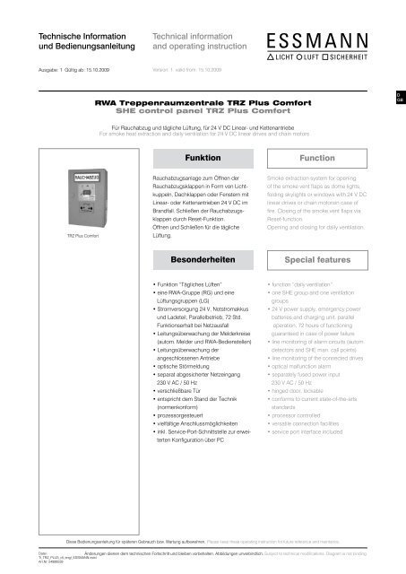
Technische Information<br />
und Bedienungsanleitung<br />
<strong>Technical</strong> <strong>information</strong><br />
<strong>and</strong> <strong>operating</strong> <strong>instruction</strong><br />
Ausgabe: 1 Gültig ab: 15.10.2009<br />
Version: 1 valid from: 15.10.2009<br />
RWA Treppenraumzentrale TRZ Plus Comfort<br />
SHE control panel TRZ Plus Comfort<br />
Für Rauchabzug und tägliche Lüftung, für 24 V DC Linear- und Kettenantriebe<br />
For smoke heat extraction <strong>and</strong> daily ventilation for 24 V DC linear drives <strong>and</strong> chain motors<br />
Funktion<br />
Function<br />
TRZ Plus Comfort<br />
Rauchabzugsanlage zum Öffnen der<br />
Rauchabzugsklappen in Form von Lichtkuppeln,<br />
Dachklappen oder Fenstern mit<br />
Linear- oder Kettenantrieben 24 V DC im<br />
Br<strong>and</strong>fall. Schließen der Rauchabzugsklappen<br />
durch Reset-Funktion.<br />
Öffnen und Schließen für die tägliche<br />
Lüftung.<br />
Smoke extraction system for opening<br />
of the smoke vent flaps as dome lights,<br />
folding skylights or windows with 24 V DC<br />
linear drives or chain motorsin case of<br />
fire. Closing of the smoke vent flaps via<br />
Reset-function.<br />
Opening <strong>and</strong> closing for daily ventilation.<br />
Besonderheiten<br />
Special features<br />
• Funktion “Tägliches Lüften”<br />
• eine RWA-Gruppe (RG) und eine<br />
Lüftungsgruppen (LG)<br />
• Stromversorgung 24 V, Notstromakkus<br />
und Ladeteil, Parallelbetrieb, 72 Std.<br />
Funktionserhalt bei Netzausfall<br />
• Leitungsüberwachung der Melderkreise<br />
(autom. Melder und RWA-Bedienstellen)<br />
• Leitungsüberwachung der<br />
angeschlossenen Antriebe<br />
• optische Störmeldung<br />
• separat abgesicherter Netzeingang<br />
230 V AC / 50 Hz<br />
• verschließbare Tür<br />
• entspricht dem St<strong>and</strong> der Technik<br />
(normenkonform)<br />
• prozessorgesteuert<br />
• vielfältige Anschlussmöglichkeiten<br />
• inkl. Service-Port-Schnittstelle zur erweiterten<br />
Konfiguration über PC<br />
• function “daily ventilation”<br />
• one SHE group <strong>and</strong> one ventilation<br />
groups<br />
• 24 V power supply, emergency power<br />
batteries <strong>and</strong> charging unit, parallel<br />
operation, 72 hours of functioning<br />
guaranteed in case of power failure<br />
• line monitoring of alarm circuits (autom.<br />
detectors <strong>and</strong> SHE man. call points)<br />
• line monitoring of the connected drives<br />
• optical malfunction alarm<br />
• separately fused power input<br />
230 V AC / 50 Hz<br />
• hinged door, lockable<br />
• conforms to current state-of-the-arts<br />
st<strong>and</strong>ards<br />
• processor controlled<br />
• versatile connection facilities<br />
• service port interface included<br />
Diese Bedienungsanleitung für späteren Gebrauch bzw. Wartung aufbewahren. Please keep these <strong>operating</strong> <strong>instruction</strong> for future reference <strong>and</strong> maintance.<br />
Datei:<br />
Änderungen dienen dem technischen Fortschritt und bleiben vorbehalten. Abbildungen unverbindlich. Subject to technical modifications. Diagram is not binding.<br />
Ti_TRZ_PLUS_dt_engl_ESSMANN.indd<br />
Art.Nr. 24999539
Inhalt<br />
Seite<br />
Funktion 1<br />
Besonderheiten 1<br />
Sicherheitshinweise 3<br />
Funktionsbeschreibung<br />
Manuelle Auslösung bei Feuer/Br<strong>and</strong>/Alarm 6<br />
Automatische Auslösung bei Feuer/Br<strong>and</strong>/Alarm 6<br />
Zurücksetzen der automatischen Melder 6<br />
Tägliche Lüftung 6<br />
Schließautomatik 7<br />
Hubbegrenzung 7<br />
LED-Anzeigen 7<br />
Schließen mit Wind-/Regenmelder 8<br />
Anschlussmöglichkeiten 8<br />
Kabelplan 9<br />
Kabellängendiagramm 10<br />
Kabelquerschnittsermittung 11<br />
Anschluss<br />
Netz 12<br />
Antriebe 12<br />
Haftmagnete / Magnetverriegelung 13<br />
Lüftungstaster 14<br />
RWA-Bedienstelle 15<br />
automatische Melder 16<br />
BMA 17<br />
Hupe / Signalleuchte 18<br />
Wind-/Regenmelder 19<br />
potenzialfreie Kontakte 19<br />
Anschlussübersicht 20<br />
Service Port 20<br />
Inbetriebnahme und Probelauf<br />
Ohne Netzspannung, ohne Akku 21<br />
Mit Netzspannung, mit Akku 21<br />
Lüftungstaster 21<br />
RWA-Bedienstellen 22<br />
Test Notstrom 22<br />
Test automatischer Melder 22<br />
Test Lüftungsautomatik 22<br />
Inbetriebnahme und Probelauf<br />
Test Wind / Regenmelder oder Regensensor 23<br />
Test Hupe / Signalleuchte 23<br />
Störungshilfe<br />
Anzeige - Betrieb OK -leuchtet nicht 23<br />
Der Rauchabzug öffnet ohne Taster-Betätigung 23<br />
Lüftungstaster mit umgekehrter Funktion 23<br />
Lüftungstaster ohne Funktion 24<br />
Kapazitäten der Akkus nicht ausreichend 24<br />
Alle LED`s dunkel 24<br />
Grüne LED OK dunkel 24<br />
Haftmagnet fällt nach kurzer Zeit ab 24<br />
Störmeldungen - Tabelle 24<br />
Wartungsanzeige 25<br />
Wind-/Regenmeldung 25<br />
Wartung 26<br />
Außer Betrieb 26<br />
Platzieren 26<br />
Einbau 27<br />
Maße 28<br />
Technische Daten 29<br />
Contents<br />
Page<br />
Function 1<br />
Special features 1<br />
Safety <strong>instruction</strong>s 3<br />
Description oerating<br />
Manual activation in case of fire/smoke/alarm 6<br />
Automatic activation in case of fire/smoke/alarm 6<br />
Reset of automatic detectors 6<br />
Daily ventilation 6<br />
Automatic ventilation control 7<br />
Extraction limit (by <strong>operating</strong> time) 7<br />
LED display 7<br />
Closing with wind/rain detector 8<br />
Possible connections 9<br />
Routing of cables 9<br />
Cable length diagram 10<br />
Cable cross-section determination 11<br />
Connecting diagram<br />
Mains 12<br />
Drives 12<br />
Magnetic clamps / magnetic looking 13<br />
Vent switch 14<br />
SHE man. call point 15<br />
Smoke detector 16<br />
FAS 17<br />
Buzzer / signal lamp 18<br />
Wind/rain detector 19<br />
potent.free contacts 19<br />
Connection diagram 22<br />
Service port 20<br />
Putting into operation <strong>and</strong> trial run<br />
Without mains voltage <strong>and</strong> without battery 21<br />
With mains voltage <strong>and</strong> battery 21<br />
Vent switches 21<br />
SHE manual call points 22<br />
Test emergency power supply 22<br />
Test automatic detectors 22<br />
Test automatic ventilation control 22<br />
Putting into operation <strong>and</strong> trial run<br />
Test wind/rain detector or rain sensor 23<br />
Test buzzer/ signal lamp 23<br />
Troubleshooting<br />
Display - <strong>operating</strong> OK - is not shining 23<br />
The drives open without pressing a switch 23<br />
Vent switch with reversed function 23<br />
Vent switch without function 24<br />
Capacitance of storage batteries is inadequately 24<br />
All LED displays are dark 24<br />
The green LED OK is dark 24<br />
Adhesive magnet falls after a moment 24<br />
Malfunction - beep code - chart 24<br />
Maintenance display 25<br />
Wind or rain signal 25<br />
Maintenance 26<br />
Out of oder 26<br />
Position 26<br />
Fitting 27<br />
Measures 28<br />
<strong>Technical</strong> data 29<br />
2
Sicherheitshinweise für Antriebe<br />
Safety <strong>instruction</strong>s for motors<br />
Sicherheitshinweise, die Sie unbedingt beachten müssen,<br />
werden durch besondere Zeichen hervorgehoben.<br />
Please observe the following safety <strong>instruction</strong>s which<br />
are emphasized by special symbols.<br />
Vorsicht: Gefahr für Personen durch elektrischen Strom.<br />
Caution: Danger to persons due to electricity.<br />
Achtung: Nichtbeachtung führt zur Zerstörung Gefährdung<br />
für Material durch falsche H<strong>and</strong>habung.<br />
Warning: Non-observance leads to destruction.<br />
Danger to material due to incorrect h<strong>and</strong>ling<br />
Warnung: Gefährdung für Personen durch Gefahren<br />
aus dem Gerätebetrieb. Quetsch- und Klemmgefahr.<br />
INFO<br />
Attention: Danger to persons due to risks arising from<br />
the operation of the equipment. Danger of crushing/trapping.<br />
INFO<br />
Warnung 230 V AC: Gefährliche Spannung. Kann Tod, schwere Körperverletzung<br />
oder erheblichen Sachschaden verursachen. Trennen Sie das Gerät allpolig von der<br />
Versorgungsspannung bevor Sie es öffnen, montieren oder den Aufbau verändern.<br />
VDE 0100 für 230 V Netzanschluss beachten.<br />
Warning 230 V AC: Dangerous voltage. Can cause death, serious injury or considerable<br />
material damage. Disconnect the equipment from the power supply at all poles<br />
before opening, assembling or carrying out any structural alterations. Observe VDE<br />
0100 for 230 V power connection.<br />
Beachten Sie bei der Montage und Bedienung: Das Fenster schließt automatisch.<br />
Beim Schließen und Öffnen stoppt der Antrieb über die Lastabschaltung. Die entsprechende<br />
Druckkraft entnehmen Sie bitte den technischen Daten. Die Druckkraft reicht<br />
aber auf jeden Fall aus bei Unachtsamkeit Finger zu zerquetschen. Bei der Montage<br />
und Bedienung nicht in den Fensterfalz und in den laufenden Antrieb greifen!<br />
Quetsch- und Klemmgefahr!<br />
Bedienungsanleitung für die fachgerechte Montage, Installation und angemessene<br />
Wartung durch den geschulten, sachkundigen und sicherheitsbewussten Elektro-<br />
Installateur und / oder Fachpersonal mit Kenntnissen der elektrischen Geräteinstallation.<br />
Lesen und Beachten Sie die Angaben in dieser Bedienungsanleitung und<br />
halten Sie die vorgegebene Reihenfolge ein. Diese Bedienungsanleitung für späteren<br />
Gebrauch / Wartung aufbewahren. Ein zuverlässiger Betrieb und ein Vermeiden von<br />
Schäden und Gefahren ist nur bei sorgfältiger Montage und Einstellung nach dieser<br />
Anleitung gegeben. Bitte beachten Sie genau die Anschlussbelegung, die minimalen<br />
und maximalen Leistungsdaten (siehe technischen Daten) und die Installationshinweise.<br />
Anwendungsbereich: ausschließlich für automatisches Öffnen und Schließen der<br />
angegebenen Fensterformen. Weitere Anwendungen im Werk erfragen.<br />
Es würde den Rahmen dieser Bedienungsanleitung sprengen, alle gültigen Bestimmungen<br />
und Richtlinien aufzulisten. Prüfen Sie immer, ob Ihre Anlage den gültigen<br />
Bestimmungen entspricht. Besondere Beachtung finden dabei: Öffnungsquerschnitt<br />
des Fensters, Öffnungszeit und Öffnungsgeschwindigkeit, Temperaturbeständigkeit<br />
von Kabel und Geräten. Benötigtes Befestigungsmaterial ist mit dem Baukörper und<br />
der entsprechenden Belastung abzustimmen und, wenn nötig, zu ergänzen. Ein eventuell<br />
mitgeliefertes Befestigungsmaterial entspricht nur einem Teil der Erfordernisse.<br />
Please observe the following for assembly <strong>and</strong> operation: the window closes automatically.<br />
When opening <strong>and</strong> closing, the drive unit is stopped by the power cut-off. The<br />
corresponding pressure force is listed in the technical data. Take care - the pressure<br />
force is high enough to crush your fingers. During assembly <strong>and</strong> operation, do not<br />
interfere with the window gap or the travelling drive! Danger of crushing/trapping!<br />
Operating <strong>instruction</strong>s: for professional assembly, installation <strong>and</strong> appropriate maintenance<br />
by trained, qualified <strong>and</strong> safety-conscious electricians <strong>and</strong>/or skilled staff with<br />
knowledge of electrical equipment installation.<br />
Read <strong>and</strong> observe the <strong>information</strong> contained in these <strong>operating</strong> <strong>instruction</strong>s <strong>and</strong> respect<br />
the order of procedure stated therein. Please keep these <strong>operating</strong> <strong>instruction</strong>s<br />
for future reference <strong>and</strong> maintenance. Reliable operation <strong>and</strong> the prevention of damage<br />
<strong>and</strong> risks are only granted if the equipment is assembled carefully <strong>and</strong> the settings<br />
are carried out according to these <strong>instruction</strong>s <strong>and</strong> to the <strong>operating</strong> <strong>instruction</strong>s of the<br />
drives. Please observe the exact terminal assignment, the minimum <strong>and</strong> maximum<br />
power ratings (see technical data) <strong>and</strong> the installation <strong>instruction</strong>s.<br />
Application range: Exclusively for the automatic opening <strong>and</strong> closing of the stated<br />
types of windows. For further application, please contact the manufacturer. It would<br />
be beyond the scope of these safety <strong>instruction</strong>s to list all the valide regulations <strong>and</strong><br />
guidelines. Always make sure that your system corresponds to the valid regulations.<br />
Pay particular attention to: the aperture cross-section of the window, the opening<br />
time <strong>and</strong> opening speed, the temperature resistance of the cables <strong>and</strong> equipment,<br />
cross-sections of the cables in relation to the cable lengths <strong>and</strong> power consumption.<br />
Required mounting material is to be adapted to the frame <strong>and</strong> the corresponding<br />
load <strong>and</strong> is to be completed, if necessary. Any supplied mounting material is only part<br />
of the required amount.<br />
Wartungsarbeiten: Werden die Geräte in Rauch- und Wärmeabzugsanlagen (kurz<br />
RWA) eingesetzt, müssen sie mindestens einmal jährlich geprüft, gewartet und ggf.<br />
inst<strong>and</strong> gesetzt werden. Bei reinen Lüftungsanlagen ist dies auch zu empfehlen.<br />
Die Geräte von Verunreinigungen befreien. Befestigungs- und Klemmschrauben auf<br />
festen Sitz prüfen. Die Geräte durch Probelauf testen. Das Motorgetriebe ist wartungsfrei.<br />
Defekte Geräte dürfen nur in unserem Werk inst<strong>and</strong> gesetzt werden. Es sind<br />
nur Original-Ersatzteile einzusetzen. Die Betriebsbereitschaft ist regelmäßig zu prüfen.<br />
Ein Wartungsvertrag ist empfehlenswert. Alle serienmäßig mit der RWA-Steuerzentrale<br />
gelieferten Akkus bedürfen einer regelmäßigen Kontrolle im Rahmen<br />
Maintenance works: If the equipment is employed in smoke heat extraction systems<br />
(in short SHE), they must be checked, serviced <strong>and</strong>, if required, repaired at least once<br />
per year. This is also recommended for pure ventilation systems.<br />
Free the equipment from any contamination. Check the tightness of fixing <strong>and</strong> clamping<br />
screws. Test the equipment by trial run.<br />
The gear system is maintenance free. Defective equipment must only be repaired in<br />
our factory. Only original spare parts are to be used. The readiness for operation has<br />
to be checked regularly. For this purpose a service contract is recommended.<br />
.<br />
3
Sicherheitshinweise für Antriebe<br />
Safety <strong>instruction</strong>s for motors<br />
der Wartung und sind nach der vorgeschriebenen Betriebszeit (ca. 4 Jahre) auszutauschen.<br />
Bei der Entsorgung der verwendeten Gefahrstoffe - z. B. Akkus - Gesetze<br />
beachten.<br />
Leitungsverlegung und elektrischer Anschluss nur durch zugelassene Elektrofirma.<br />
Netzzuleitungen 230 V AC separat bauseits absichern. Netzzuleitungen bis an<br />
die Netzklemme ummantelt lassen. Bei der Installation DIN- und VDE-Vorschriften<br />
beachten, VDE 0100 Errichten von Starkstromanlagen bis 1000 V, VDE 0815 Installationskabel<br />
und -leitungen, VDE 0833 Gefahrenmeldeanlagen für Br<strong>and</strong>, Einbruch<br />
und Überfall. Kabeltypen ggf. mit den örtlichen Abnahmebehörden, Energieversorgungsunternehmen,<br />
Br<strong>and</strong>schutzbehörden oder Berufsgenossenschaften festlegen.<br />
Alle Kleinspannungsleitungen (24 V DC) getrennt von Starkstromleitungen verlegen.<br />
Flexible Leitungen dürfen nicht eingeputzt werden. Frei hängende Leitungen mit<br />
Zugentlastung versehen. Die Leitungen müssen so verlegt sein, dass sie im Betrieb<br />
weder abgeschert, verdreht noch abgeknickt werden. Abzweigdosen müssen für<br />
Wartungsarbeiten zugänglich sein. Die Kabelarten, -längen und -querschnitte gemäß<br />
den technischen Angaben ausführen.<br />
Vor jeder Wartungsarbeit oder Veränderung des Aufbaus sind<br />
die Netzspannung und Akkus allpolig abzuklemmen. Gegen unbeabsichtigtes<br />
Wiedereinschalten ist die Anlage abzusichern. Elektrische Steuerungen<br />
müssen stromlos sein, bevor Sie Teile entnehmen oder dazusetzen (Netzspannung<br />
und Akkus abklemmen).<br />
Nach der Installation und jeder Veränderung der Anlage alle Funktionen durch<br />
Probelauf überprüfen.<br />
Beachten Sie bei der Montage und Bedienung: Die Fenster schließen automatisch.<br />
Quetsch- und Scherstellen zwischen Fensterflügel und Rahmen, Lichtkuppeln und<br />
Aufsetzkranz müssen bis zu einer Höhe von 2,5 m durch Einrichtungen gesichert<br />
sein, die bei Berührung oder Unterbrechung durch eine Person, die Bewegung zum<br />
Stillst<strong>and</strong> bringen (Richtlinie für kraftbetätigte Fenster, Türen und Tore der Berufsgenossenschaften).<br />
Achtung! Die Antriebe und Bedienstellen niemals an 230 V anschließen!<br />
Sie sind für 24 V gebaut! Lebensgefahr!<br />
Bei Anwendungen am Kippfenster muss eine Kippfang-Sicherungsschere eingebaut<br />
werden. Sie verhindert Schäden, die bei unsachgemäßer Montage und H<strong>and</strong>habung<br />
auftreten können. Bitte beachten: die Kippfang-Sicherungsschere muss mit dem<br />
Öffnungshub des Antriebes abgestimmt sein. Das heißt, die Öffnungsweite der<br />
Kippfang-Sicherungsschere muss, um eine Blockade zu vermeiden, größer als der<br />
Antriebshub sein. Siehe Richtlinie für kraftbetätigte Fenster, Türen und Tore. Schützen<br />
Sie alle Aggregate dauerhaft vor Wasser und Schmutz.<br />
All batteries provided with the SHE control panel need to be regularly checked as<br />
part of the maintenance programme <strong>and</strong> have to be replaced after their specified<br />
service life (approx. 4 years). Please observe the legal requirements when disposing<br />
of hazardous material - e.g. batteries.<br />
Routing of cables <strong>and</strong> electrical connections only to be done by a qualified electrician.<br />
Power supply leads 230 V AC to be fused separately by the customer. Keep<br />
power supply leads sheathed until the mains terminal.<br />
DIN <strong>and</strong> VDE regulations to be observed for the installation: VDE 0100 Setting up<br />
of high voltage installations up to 1000 V. VDE 0815 Installation cables <strong>and</strong> wires.<br />
VDE 0833 Alarm systems for fire, break-in <strong>and</strong> burglary.<br />
Cable types to be agreed with local inspection authorities, power utilities, fire<br />
protection authority <strong>and</strong> the professional associations.<br />
All low voltage cables (24 V DC) to be installed separately from high voltage cables.<br />
Flexible cables must not be plastered in. Provide tension relief for freely suspended<br />
cables. The cables must be installed in such a way that they cannot be sheared<br />
off, twisted or bent off during operation. Junction boxes must be accessible for<br />
maintenance work. Adhere to the type of cables, cable lengths <strong>and</strong> cross-sections<br />
as stated in the technical <strong>information</strong>.<br />
The supply voltage <strong>and</strong> the batteries are to be disconnected at all<br />
poles before maintenance work or structural alterations. The system<br />
must be protected against unintentional re-starting. Electrical controls must be<br />
voltage free before extension modules are taken off or added (disconnect mains<br />
voltage <strong>and</strong> batteries).<br />
After installation <strong>and</strong> any changes to the system check all functions by a trial run.<br />
During assembly <strong>and</strong> operation, please observe: the windows may close automatically.<br />
Potential crushing <strong>and</strong> cutting points between the casement <strong>and</strong> the window<br />
frame, dome lights <strong>and</strong> support frame must be secured up to a height of 2.5 m<br />
by safety equipment, which if touched or interrupted by a person will immediately<br />
stop the movement (guideline for power operated windows, doors <strong>and</strong> gates of the<br />
professional association).<br />
Warning! Never connect the drives <strong>and</strong> call points to 230 V!<br />
They are built for 24 V! Risk of death!<br />
For applications: Tilt windows: A scissor-type safety catch is to be installed. It<br />
prevents damage caused by incorrect assembly <strong>and</strong> h<strong>and</strong>ling. Please observe: the<br />
scissor-type safety catch must be adapted to the opening stroke of the drive unit,<br />
i.e. that the opening of the safety catch must be larger than the drive unit stroke in<br />
order to prevent blocking. See guideline for power-operated windows, doors <strong>and</strong><br />
gates. Provide all aggregates with durable protection against water <strong>and</strong> dirt!<br />
Achtung: Die Antriebe nur mit Steuerungen vom gleichen<br />
Hersteller betreiben. Bei Verwendung von Fremdfabrikaten keine<br />
Haftung, Garantie- und Serviceleistungen. Die Montage und Installation muss sachgemäß,<br />
sicherheitsbewusst und nach Angaben der Bedienungsanleitung erfolgen.<br />
Werden Ersatzteile, Ausbauteile oder Erweiterungen benötigt bzw. gewünscht,<br />
ausschließlich Original-Ersatzteile verwenden.<br />
Herstellererklärung: Die Geräte sind gemäß der europäischen Richtlinien geprüft und<br />
hergestellt. Eine entsprechende Herstellererklärung liegt vor. Sie dürfen die Geräte<br />
nur dann betreiben, wenn für das Gesamtsystem eine Konformitätserklärung vorliegt.<br />
Attention: The control must only be operated with drives made by the<br />
same manufacturer. No liability will be accepted <strong>and</strong> no guarantee nor<br />
service is granted if products of outside manufacturers are used. Assembly <strong>and</strong><br />
installation must be carried out properly, according to the <strong>information</strong> of the <strong>operating</strong><br />
<strong>instruction</strong>s paying particular attention to safety aspects. If spare parts, dismantled<br />
parts or extension components are required or desired, only use original spare<br />
parts.<br />
Manufacturer’s declaration<br />
The equipment has been manufactured <strong>and</strong> tested according to the European<br />
regulations. A corresponding manufacturer’s declaration has been submitted. You<br />
may only operate the system if a Declaration of Conformity exists for the entire<br />
system.<br />
4
Funktionsbeschreibung<br />
Description of <strong>operating</strong><br />
Manuelle Auslösung bei Feuer/Br<strong>and</strong>/Alarm<br />
Rauchabzug / Fenster öffnen<br />
rote AUF-Taste in einer RWA-Bedienstelle drücken, Fenster<br />
werden vollständig geöffnet, rote LED-Anzeige - RWA<br />
ausgelöst - leuchtet in allen RWA-Bedienstellen, die Lüftungsfunktion<br />
ist außer Betrieb.<br />
Manual activation in case of fire/smoke/alarm<br />
Smoke heat extraction / opening windows<br />
Press the red OPEN switch at a SHE manual call point, the<br />
windows open completely, the red LED display - SHE<br />
activated - is shining at all SHE manual call points, the ventilation<br />
function is out of order.<br />
Rauchabzug / Fenster schließen<br />
ZU-Taste in einer RWA-Bedienstelle drücken, Fenster<br />
schließen, die rote LED-Anzeige - RWA ausgelöst - erlischt in<br />
allen RWA-Bedienstellen, Lüftungsfunktion ist wieder in Betrieb.<br />
Hinweis: es erfolgt kein Zurücksetzen (Reset) der<br />
angeschlossenen und ausgelösten automatischen Melder!<br />
Automatische Auslösung bei Feuer/Br<strong>and</strong>/Alarm<br />
nur wenn automatische Melder angeschlossen sind.<br />
Rauchabzug / Fenster öffnen<br />
Rauch erreicht die automatischen Melder, Fenster werden<br />
vollständig geöffnet, rote Anzeige im automatischen Melder<br />
leuchtet, rote LED-Anzeige - RWA ausgelöst - leuchtet in allen<br />
RWA-Bedienstellen, die Lüftungsfunktion ist außer Betrieb.<br />
Rauchabzug / Fenster schließen<br />
ZU-Taste in einer RWA-Bedienstelle drücken, Fenster<br />
schließen, die rote LED-Anzeige - RWA ausgelöst - erlischt in<br />
allen RWA-Bedienstellen, gelbe LED - Störung - blinkt.<br />
Hinweis: es erfolgt kein Zurücksetzen (Reset) der<br />
angeschlossenen und ausgelösten automatischen Melder!<br />
Zurücksetzen der automatischen Melder<br />
Automatische Melder von Rauch befreien (durch Ausblasen bzw.<br />
bei starker Verschmutzung ersetzen).<br />
Taste RWA-RESET in der Steuerzentrale (auf Platine) drücken, alle<br />
angeschlossenen automatischen Melder werden zurückgesetzt<br />
(Reset), Fenster schließen, rote Anzeige im automatischen Melder<br />
erlischt, die rote LED-Anzeige - RWA ausgelöst - erlischt in<br />
allen RWA-Bedienstellen, die gelbe LED-Anzeige - Störung<br />
- erlischt, die Lüftungsfunktion ist wieder in Betrieb.<br />
Tägliches Lüften<br />
nur wenn Lüftungstaster angeschlossen sind, bzw. am Bedienelement<br />
der TRZ Plus Comfort.<br />
Fenster öffnen<br />
am Lüftungstaster AUF-Taste kurz drücken, Fenster wird<br />
vollständig geöffnet. (Unterbrechen des Öffnungsvorgangs durch<br />
kurzes gemeinsames Antippen beider Tasten (Auf und Zu) = STOP<br />
oder durch Taste Stop je nach Lüftungstaster).<br />
Fenster schließen<br />
am Lüftungstaster ZU-Taste kurz drücken, Fenster schließen<br />
vollständig. (Unterbrechen des Schließvorgangs durch kurzes<br />
gemeinsames Antippen beider Tasten (Auf und Zu) = STOP oder<br />
durch Taste Stop je nach Lüftungstaster).<br />
Bei Netz- oder Akkuausfall schließen die Fenster sofort.<br />
Smoke heat extraction / closing windows<br />
Press the switch “closed” at a SHE manual call point, the<br />
windows are closing, the red LED display - SHE activated<br />
- goes out at all SHE manual call points, the ventilation function is<br />
working again.<br />
Note: there is no reset of the connected <strong>and</strong> activated<br />
automatic detectors!<br />
Automatic activation in case of fire/smoke/alarm<br />
if automatic detectors are connected only.<br />
Smoke heat extraction / opening windows<br />
Smoke reaches the automatic detectors, the windows are opened<br />
completely, the red display in the automatic detector is shining, the<br />
red LED display - SHE activated - is shining at all SHE manual<br />
call points, the ventilation function is out of order.<br />
Smoke heat extraction / closing windows<br />
Press the switch “closed” at a SHE manual call point, the<br />
windows are closing, the red LED display - SHE activated -<br />
goes out at all SHE manual call points, the yellow LED display<br />
- malfunction - flashes.<br />
Note: there is no reset of the connected <strong>and</strong> activated<br />
automatic detectors!<br />
Reset of automatic detectors<br />
Set the automatic detectors free from smoke by blowing out or<br />
replace them in case of heavy soiling.<br />
Press the RESET switch on the basic circuit control board of the<br />
control panel, the windows are closing, the red display in the automatic<br />
detectors goes out, the red LED display - SHE activated<br />
- goes out at all SHE manual call points, the yellow LED display<br />
- malfunction - goes out, the ventilation function is working<br />
again.<br />
Daily ventilation<br />
If vent switches are connected only respectively via <strong>operating</strong><br />
element of the TRZ Plus Comfort.<br />
Opening windows<br />
Press the switch “open” at the vent switch, the windows open<br />
completely. (Interruption of the opening by pressing both switches<br />
together (Open <strong>and</strong> Closed) = STOP or by Stop switch depending<br />
on vent switch).<br />
Closing windows<br />
Press the switch “closed” at the vent switch, the windows close<br />
completlely. (Interruption of the opening by pressing both switches<br />
together (Open <strong>and</strong> Closed) = STOP or by Stop switch depending<br />
on vent switch). In case of mains or battery failure, the windows<br />
close immediately.<br />
5
Funktionsbeschreibung<br />
Description of <strong>operating</strong><br />
Schließautomatik<br />
Ist die Automatik aktiv (siehe Inbetriebnahme), schließen die Fenster<br />
selbständig nach der eingestellten Zeit (werkseitig auf 10 Min.<br />
eingestellt), bei Netz- oder Akkuausfall schließen die Fenster sofort.<br />
Automatic ventilation control<br />
If activated (see putting into operation), the windows are closing<br />
automatically after xx min. (10 min.factory-made), in case of mains<br />
or battery failure, the windows close immediately.<br />
Einlernen<br />
Die Fenster schließen!<br />
Frühstens die Lernmodus nach 30 Sekunden starten. Die Tasten<br />
Auf und Zu (STOP) am Lüftungstaster drücken und solange gedrückt<br />
halten bis ein schnelles<br />
Blinken der Auf-Anzeige erscheint. Innerhalb der nächsten 10 Sek.<br />
mit der Taste „Auf“ die Öffnungsposition auffahren und bei gewünschter<br />
Öffnungsposition Taste „Auf“ loslassen. Erfolgt innerhalb<br />
von 10 Sek. kein weiterer Tastendruck ist der Lernmodus beendet.<br />
Teaching<br />
Close the windows!<br />
Earliest start of the learning mode after 30 seconds. Press the<br />
switches “open” <strong>and</strong> “closed” (STOP) at the vent switch as long as<br />
the display “open” is flashing fast. Open the motor with the switch<br />
“open” up to the position required within the next 10 sec. <strong>and</strong> stop<br />
the motor in this position by releasing the switch “open”. If no other<br />
switch is pressed within the next 10 sec. the learning phase is<br />
finished.<br />
Hinweis: bei Netz- oder Akkuausfall oder bei RWA-<br />
Auslösung ist die Lüftungsfunktion außer Betrieb. Bei Netz- oder<br />
Akkuausfall schließen die Fenster sofort.<br />
Note: in case of mains or battery failure or SHE activation<br />
the function is out of order. In case of mains or battery failure, the<br />
windows close immediately.<br />
LED-Anzeigen<br />
In der Steuerzentrale und in den RWA-Bedienstellen.<br />
LED display<br />
In the SHE control panel <strong>and</strong> SHE manual call points.<br />
Die grüne LED-Anzeige OK - Betrieb OK - leuchtet. Sie erlischt bei:<br />
- Netz- oder Akkuausfall<br />
- Störung der Leitungsüberwachung zu den Antrieben, RWA-Bedienstellen<br />
oder automatischen Meldern.<br />
Die gelbe LED-Anzeige - Störung - blinkt:<br />
eine Störung steht an, Leitungsanschluss defekt, Netz und/oder<br />
Akku defekt.<br />
Bei jeglicher Störmeldung muss unbedingt sofort die<br />
Störung beseitigt werden. Eine reibungslose Funktion der<br />
Anlage ist nicht mehr gewährleistet.<br />
Die rote LED-Anzeige - RWA ausgelöst - leuchtet:<br />
nach Drücken der AUF-Taste in einer RWA-Bedienstelle und nach<br />
dem Auslösen durch automatische Melder.<br />
The green LED display OK - <strong>operating</strong> OK - is shining. It goes out<br />
in case of:<br />
- mains or battery failure<br />
- malfunction of the line monitoring of the connected drives,<br />
automatic detectors or SHE manual call points.<br />
The yellow LED display - malfunction - is flashing in case of:<br />
malfunction, cable connection defective, mains <strong>and</strong>/or battery<br />
failure.<br />
If any malfunction is indicated the malfunction has to be<br />
eleminated immediately. The perfect function of the<br />
system is not longer guaranteed.<br />
The red LED display - SHE activation - is shining in case of:<br />
manual or automatic SHE activation.<br />
6
Funktionsbeschreibung<br />
Description of <strong>operating</strong><br />
Schließen mit Wind-/Regenmelder<br />
Ist ein Wind-/Regenmelder oder Regensensor angeschlossen,<br />
schließen die Fenster bei einsetzendem Wind und/oder Regen<br />
selbständig. Die Anzeige “Lüftung Auf” in der Steuerzentrale blinkt,<br />
die Lüftungsfunktion ist außer Betrieb. Bei Netz- oder Akkuausfall<br />
schließen die Fenster sofort.<br />
Hinweis: Bei Ausfall der Netz- oder Akkuspannung<br />
oder bei RWA-Auslösung ist die Lüftungsfunktion aus<br />
Gründen der Akkuschonung außer Betrieb bzw. gesperrt.<br />
Closing with wind/rain detector<br />
If a wind/rain detector or a rain sensor is connected, the windows<br />
close automatically in case of beginning winds <strong>and</strong>/or rainfall, “Ventilation<br />
Open” display flashes, vent switch out of order, the windows<br />
close immediately in case of power or battery failure.<br />
Note: The ventilation function is out of order or locked in<br />
case of power or battery failure or SHE activation in order<br />
to save battery power.<br />
Anschlussmöglichkeiten<br />
- 24 V DC Linearantriebe mit elektronischer Lastabschaltung,<br />
T<strong>and</strong>emlastabschaltung, Synchronmodul oder<br />
- 24 V DC Kettenantriebe mit Endschaltern oder Lastabschaltung<br />
- gesamte Stromaufnahme aller angeschlossenen Antriebe<br />
max. 2 A<br />
- 10 RWA-Bedienstellen RBH/3A... (Linienabschluss über<br />
beiliegenden Endwiderst<strong>and</strong>)<br />
- 10 automatische Melder in 2-Leiter-Technik, optische Rauchmelder<br />
und/oder Wärmedifferential-Melder und/oder Wärmemaximal-Melder<br />
(Linienabschluss mit aktivem Endmodul oder<br />
Endwiderst<strong>and</strong>) Werkseitig über beiliegenden Endwiderst<strong>and</strong><br />
- 10 externe Lüftungstaster AUF/STOP/ZU (z. B.: Typ LTA 25)<br />
- 24 V DC Sirene oder Blitzleuchte, max. 100 mA<br />
- Anschluss für einen Wind-/Regenmelder (z. B.: Typ WRM24V, WRM2)<br />
oder einen Regenmelder (z. B.: RM, RM2). Nur bei TRZ Plus Comfort oder mit<br />
Zusatzmodul WRMAS<br />
- je einen Anschluss für potenzialfreie Meldung: RWA Auslösung<br />
(Schließer) und Störung (Öffner); 24V / max. 0,5 A (nur bei TRZ Plus<br />
Comfort oder mit Zusatzmodul WRMAS)<br />
M1<br />
=<br />
Possible connections<br />
- linear drives 24 V DC with integrated electronic power cut-off,<br />
T<strong>and</strong>em power cut-off, scnchro modul or<br />
- chain motors 24 V DC with limit switches<br />
- overall power consumption of all motors connected: max. 2 A<br />
- 10 SHE manual call points RBH/3A... (line termination via<br />
enclosed end resistance)<br />
- 10 automatic detectors with 2-wire-technology, optical smoke<br />
detectors <strong>and</strong>/or detectors of heat ifferential <strong>and</strong>/or detectors<br />
of maximum heat or monotoring resistor ex factory via the final fuse<br />
attached.<br />
- 10 external ventilation switches “open”/”stop”/”closed”<br />
(e.g. type LTA 25)<br />
- 24 V DC sirenor flashing lights, max 100 mA<br />
- to connect 1 wind-/rain detector (e.g. type WRM 24V, WRM2) or 1 rain<br />
detector (e,g.RM, RM2). With TRZ Plus Comfort only or with additional module<br />
WRMAS<br />
- in each case one connection for potential-free report SHE<br />
activated (NO= normally open contact) <strong>and</strong> malfunction (NC=<br />
normally closed contact); 24V / max. 0.5 A .With TRZ Plus Comfort only or<br />
with additional module WRMAS<br />
230 V DC<br />
Lüftung/VENT<br />
STOP<br />
Rauchabzug<br />
Smoke heat extraction<br />
L1 N 1 2 3 8 9 10 11 12 13 14 15 16 17 18 19 20 21<br />
Sicherung<br />
Fuse<br />
F1 Netz<br />
F1 mains<br />
RESET<br />
Taster “RWA-ZU”, Reset<br />
Switch “SHE closed“,<br />
reset<br />
F2 Motor<br />
Erweiterungsleiste<br />
Extension ledge<br />
OK<br />
!<br />
ON<br />
OFF<br />
F3 Akku<br />
F3 battery<br />
1 2 3 4 5 6 7 8 910 1112<br />
STG-B.<br />
Port<br />
DIP-Schalter<br />
DIP-switch<br />
PC Schnittstelle<br />
Service Port<br />
Sicherung Akku<br />
Fuse battery<br />
<br />
12V<br />
Sicherung<br />
Fuse<br />
M1<br />
=<br />
LED-Anzeigen<br />
LED display<br />
Akku<br />
battery<br />
- +<br />
12V<br />
Akkuanschluss<br />
Battery connection<br />
7
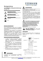
Kabelplan TRZ Plus Comfort<br />
Routing of cables TRZ Plus Comfort<br />
*bei TRZ Plus Comfort mit Erweiterung durch<br />
Zusatzplatine WRMAS<br />
*by TRZ Plus Comfort with expansion via additional print circuit<br />
board WRMAS<br />
Es sind die gültigen Vorgaben bzgl. einer Verkabelung mit Funktionserhalt<br />
30 Min. oder 90 Min. einzuhalten. Abweichungen hierzu<br />
sind in jedem Fall mit der Bauleitung, mit den örtlichen Abnahmebehörden,<br />
Energieversorgungsunternehmen, Br<strong>and</strong>schutzbehörden<br />
oder der Berufsgenossenschaft abzustimmen. Die angegebenen<br />
Leitungsquerschnitte dürfen nicht verringert werden. Sie sind<br />
für eine Umgebungstemperatur von 20 °C angegeben. Für höhere<br />
Temperaturen, die Querschnitte erhöhen. Bei E90 (E30) müssen<br />
die Leitungsquerschnitte entsprechend den Vorschriften des<br />
Herstellers angepasst werden. Alle Leitungen zu der Steuerzentrale<br />
(außer Netzzuleitung) führen 24 V DC und müssen getrennt von der<br />
Netzzuleitung verlegt werden. Bei der Leitungsverlegung sind die<br />
entsprechenden VDE-Vorschriften zu beachten<br />
Make sure all cable types <strong>and</strong> specifications are according to<br />
site management requirements <strong>and</strong> the appropriate national <strong>and</strong><br />
local codes <strong>and</strong> laws. The stated cable cross sections must not<br />
be reduced. They are listed for an ambient temperature of 20 °C.<br />
Increase the cross sections for higher temperatures. For E90 (E30),<br />
all cable cross sections must be adapted to the manufacturer’s<br />
specifications. All cables to the control panel (except the mains<br />
supply lead) carry 24 V DC <strong>and</strong> must be routed separately from the<br />
mains supply lead. When routing the cables, please observe the<br />
corresponding VDE regulations.<br />
8
Kabellängendiagramm<br />
Cable length diagram<br />
Zur Ermittlung der notwendigen Kabelquerschnitte in Abhängigkeit<br />
der Leitungslänge und der Summe der Nennströme der Antriebe.<br />
To determine the necessary cable cross-sections as a function of<br />
the line length <strong>and</strong> the sum of the rated currents of the drives.<br />
500<br />
<br />
<br />
<br />
<br />
<br />
Kabellängendiagramm bis 2 Ampere für Antriebe mit einer Stromaufnahme < 2,5 A<br />
Cable length diagram up to 2 amps for drives with a current draw < 2.5 A<br />
500<br />
<br />
<br />
450<br />
e)<br />
450<br />
e)<br />
400<br />
350<br />
400<br />
d)<br />
350<br />
d)<br />
300<br />
250<br />
c)<br />
300<br />
250<br />
c)<br />
200<br />
b)<br />
200<br />
b)<br />
150<br />
100<br />
50<br />
150<br />
a)<br />
100<br />
50<br />
a)<br />
0<br />
0<br />
1 2<br />
1 2<br />
Nennstrom Antrieb in Ampere<br />
Nominal drive current in amps<br />
<br />
<br />
<br />
<br />
<br />
m (einfache Leitungslänge)<br />
Kabelquerschnittsermittlung<br />
Cable cross-section determination<br />
* einfache Kabellänge<br />
* simple cable length<br />
m (simple line length)<br />
9
Kabelquerschnittsermittlung<br />
Cable cross-section determination<br />
Hinweise zur Kabelquerschnittsermittlung und Leitungsverlegung<br />
Vereinfachte Formel zur Kabelquerschnittsermittlung<br />
Für Antriebe bis 2,5 A Nennstromaufnahme<br />
Notes re cable cross-section determination <strong>and</strong> cabling<br />
layout<br />
Simplified formulae for cable cross-section determination<br />
For drives up to 2.5 A nominal curent draw<br />
Hinweise: Zulässige Stromabgaben der TRZ Plus<br />
beachten, siehe Technische Daten.<br />
Note: permissible current supply of the TRZ plus has<br />
to be considered, see technical data<br />
A [mm²] =<br />
*<br />
I [A] x L [m]<br />
73<br />
A [mm²] =<br />
*<br />
I [A] x L [m]<br />
73<br />
A = Kabelquerschnitt<br />
I = Summe der Nennströme Antriebe<br />
*L = einfache Kabellänge<br />
73 = Faktor, bestehend aus max. zulässigem Spannungsabfall<br />
2,5 V und elektr. Leitfähigkeit von Kupfer<br />
Antrieb<br />
Motor<br />
braun<br />
brown<br />
blau<br />
blue<br />
AbzweigdoseJunction box<br />
A = cable cross-section<br />
I = sum of the rated drive current draws<br />
*L = simple line length<br />
73 = factor, made up from 2.5 V max. permissible voltage drop <strong>and</strong><br />
electrical<br />
conductivity of copper<br />
Verkabelungsbeispiel<br />
Cabling example<br />
Motorspannung<br />
Motor voltage<br />
Leitungsüberwachung<br />
Cabling monitoring<br />
Hinweise zur Auswahl der Leitungen<br />
Für die Motorzuleitungen von RWA Antrieben werden 3 bzw. 5<br />
Einzeladern (doppelt aufgelegt) benötigt.<br />
Zwei Adern (4 Adern) sind für die Motorspannung, die 3. bzw. 5.<br />
Ader wird für die Überwachung der Leitung benötigt.<br />
Die Auswahl und die Verlegung der Kabel ist gemäß (Muster-) Leitungsanlagenrichtlinie<br />
(MLAR) auszuführen. Hierbei ist insbesondere<br />
auf den Funktionserhalt E30 oder E90 zu achten!<br />
Beispiele für verwendbare Kabeltypen und Befestigungen<br />
Notes re selection of cables<br />
For the motor supply cables of SHE drives 3 or 5 (duplicated layout)<br />
individual cores are required.<br />
Two cores (4 cores) are for the motor voltage, the 3rd or 5th core<br />
respectively is required for monitoring the cabling.<br />
The selection <strong>and</strong> layout of the cables is to be performed according<br />
to (model) utility facilities guidelines (MLAR). Here particular<br />
attention is to be paid to E30 or E90 functionality retention!<br />
Examples of cable types <strong>and</strong> fittings that can be used<br />
E30 / E90 Kabel<br />
E30 / E90 cable<br />
Gelb-grün: nicht zulässig für die Leitungsüberwachung<br />
Yellow-green: cannot be used for the cabling monitoring<br />
Kabelanlage, bestehend aus Tragesystem und Kabeln mit entsprechend<br />
br<strong>and</strong>schutztechnisch geprüften Dübeln und Schrauben.<br />
Kabelanlage nach DIN 4102-12<br />
Sicherheitskabel + Verlegesystem<br />
Cable system, consisting of load support system <strong>and</strong> cables with<br />
appropriate fire protection tested wall plugs <strong>and</strong> screws.<br />
Cable system in accordance with DIN 4102-12<br />
Safety cable + layout system<br />
10
Anschluss Netz / Anschluss Antriebe<br />
Connecting diagram mains / drives<br />
Alle Arbeiten ohne Netz (230 V AC) und ohne angeschlossene<br />
Akkus/Batterien.<br />
Anschlussleitungen von oben in das Gehäuse der Steuerzentrale<br />
führen.<br />
Anschlussleitungen nach Klemmplan anklemmen, hierbei auf<br />
richtigen Anschluss achten. Falsches Anklemmen sowie Nummernoder<br />
Farbendreher können zu Fehlfunktionen der Steuerzentrale<br />
oder der externen Elemente führen.<br />
Die Hinweise und Installationsvorschriften in den technischen<br />
Dokumentationen sind immer zu beachten!<br />
All work to be carried out without mains supply (230 V AC) or any<br />
batteries connected.<br />
Route the connecting cables into the control panel housing at the<br />
top.<br />
Connect all connecting cables according to the wiring diagram <strong>and</strong><br />
make sure that they are correctly connected. Incorrected<br />
connections or figure or colour mix-ups can lead to incorrect<br />
function of the control panel or of the external components.<br />
The notes <strong>and</strong> installation directives in the technical documentation<br />
are always to be observed.<br />
Anschluss Netz (230 V AC)<br />
Connecting diagram mains (230 V AC)<br />
L1 N<br />
PE<br />
L1 N<br />
PE<br />
L1 N<br />
PE PE<br />
Separat abschaltbaren Stromkreis vorsehen.<br />
Vor unbeabsichtigtem Abschalten sichern.<br />
L1 N PE PE<br />
Provide a separately disconnectible circuit.<br />
Secure against unintentional switching-off.<br />
Anschlussplan Antrieb<br />
ein Antrieb<br />
one drive<br />
Connecting diagram drive<br />
mehrere Antriebe je Motorkreis<br />
several drives per motor circuit<br />
M =<br />
M =<br />
M =<br />
ein Antrieb<br />
one drive<br />
braun<br />
brown<br />
blau<br />
blue<br />
Abzweigdose<br />
Junction box<br />
M =<br />
1 2 3<br />
letzter Antrieb<br />
last drive<br />
braun<br />
brown<br />
blau<br />
blue<br />
1. Antrieb<br />
1.drive<br />
M =<br />
M =<br />
braun<br />
brown<br />
blau<br />
blue<br />
Abzweigdose<br />
Junction box<br />
Überwachungsdioden<br />
Monitoring diodes<br />
1 2 3<br />
24 V DC<br />
- +<br />
24 V DC<br />
+<br />
-<br />
1 2 3<br />
11
Haftmagnete / Magnetverriegelung<br />
Magnetic clamps / magnetic looking<br />
Alle Arbeiten ohne Netz (230 V AC) und ohne angeschlossene<br />
Akkus/Batterien.<br />
Anschlussleitungen von oben in das Gehäuse der Steuerzentrale<br />
führen.<br />
Anschlussleitungen nach Klemmplan anklemmen, hierbei auf<br />
richtigen Anschluss achten. Falsches Anklemmen sowie Nummernoder<br />
Farbendreher können zu Fehlfunktionen der Steuerzentrale<br />
oder der externen Elemente führen.<br />
Die Hinweise und Installationsvorschriften in den technischen<br />
Dokumentationen sind immer zu beachten!<br />
All work to be carried out without mains supply (230 V AC) or any<br />
batteries connected.<br />
Route the connecting cables into the control panel housing at the<br />
top.<br />
Connect all connecting cables according to the wiring diagram <strong>and</strong><br />
make sure that they are correctly connected. Incorrected<br />
connections or figure or colour mix-ups can lead to incorrect<br />
function of the control panel or of the external components.<br />
The notes <strong>and</strong> installation directives in the technical documentation<br />
are always to be observed.<br />
Haftmagnetverriegelung*<br />
Magnetic looking*<br />
Haftmagnetverriegelung*<br />
Magnetic looking*<br />
-<br />
+<br />
-<br />
+<br />
Haftmagnet*<br />
Magnetic clamp*<br />
Haftmagnet*<br />
Magnetic clamps*<br />
-<br />
+<br />
Überwachungsdioden<br />
Monitoring diodes<br />
ein Haftmagnet / Haftmagnetverriegelung<br />
one magnetic clamp / magnetic looking<br />
mehrere Haftmagnete / Haftmagnetverriegelungen<br />
several magnetic clamps / magnetic lokings<br />
-<br />
+<br />
Abzweigdose<br />
Junction box<br />
Letzter Haftmagnet<br />
last magnetic clamps<br />
-<br />
+<br />
Abzweigdose<br />
Junction box<br />
1 2 3<br />
24 V DC + -<br />
Haftmagnet<br />
magnetic clamp<br />
24 V DC +<br />
0 V DC<br />
-<br />
*1<br />
0 V DC<br />
*2<br />
-<br />
1 2 3<br />
Haftmagnet 1<br />
magnetic clamps 1<br />
+<br />
1 2 3<br />
*1 Öffnen durch Federkraft der Gasduckfeder<br />
*2 Schließen durch Federkraft der<br />
Türschließer<br />
*1 opening via spring force of the<br />
gas spring<br />
*2 closing via spring force of the<br />
door closer<br />
12
Anschluss Lüftungstaster<br />
Connecting diagram vent switch<br />
Alle Arbeiten ohne Netz (230 V AC) und ohne angeschlossene<br />
Akkus/Batterien.<br />
Anschlussleitungen von oben in das Gehäuse der Steuerzentrale<br />
führen. Anschlussleitungen nach Klemmplan anklemmen, hierbei<br />
auf richtigen Anschluss achten. Falsches Anklemmen sowie<br />
Nummern- oder Farbendreher können zu Fehlfunktionen der<br />
Steuerzentrale oder der externen Elemente führen.<br />
Die Hinweise und Installationsvorschriften in den technischen<br />
Dokumentationen sind immer zu beachten!<br />
All work to be carried out without mains supply (230 V AC) or any<br />
batteries connected.<br />
Route the connecting cables into the control panel housing at the<br />
top. Connect all connecting cables according to the wiring diagram<br />
<strong>and</strong> make sure that they are correctly connected. Incorrected<br />
connections or figure or colour mix-ups can lead to incorrect<br />
function of the control panel or of the external components.<br />
The notes <strong>and</strong> installation directives in the technical documentation<br />
are always to be observed.<br />
ein Lüftungstaster LTA11<br />
one vent switch LTA11<br />
ein Lüftungstaster LTA25<br />
one vent switch LTA25<br />
STOP<br />
S<br />
P<br />
O<br />
S<br />
P<br />
O<br />
3 2 1 4<br />
Jumper<br />
11 10 8<br />
11 10 9 8<br />
mehrere Lüftungstaster LTA11<br />
several vent switches LTA11<br />
mehrere Lüftungstaster LTA25<br />
several vent switches LTA25<br />
STOP<br />
STOP<br />
letzter Taster<br />
last vent switch<br />
STOP<br />
letzter Taster<br />
last vent switch<br />
S<br />
P<br />
O<br />
S<br />
P<br />
O<br />
3 2 1 4<br />
Jumper<br />
S<br />
P<br />
O<br />
S<br />
P<br />
O<br />
3 2 1 4<br />
11 10 8<br />
15 16 17 18<br />
19 20 21 22<br />
13
Anschluss RWA-Bedienstelle<br />
Connect. diagram SHE man. call point<br />
Alle Arbeiten ohne Netz (230 V AC) und ohne angeschlossene<br />
Akkus/Batterien.<br />
Anschlussleitungen von oben in das Gehäuse der Steuerzentrale<br />
führen. Anschlussleitungen nach Klemmplan anklemmen, hierbei<br />
auf richtigen Anschluss achten. Falsches Anklemmen sowie<br />
Nummern- oder Farbendreher können zu Fehlfunktionen der<br />
Steuerzentrale oder der externen Elemente führen.<br />
Die Hinweise und Installationsvorschriften in den technischen<br />
Dokumentationen sind immer zu beachten!<br />
All work to be carried out without mains supply (230 V AC) or any<br />
batteries connected.<br />
Route the connecting cables into the control panel housing at the<br />
top. Connect all connecting cables according to the wiring diagram<br />
<strong>and</strong> make sure that they are correctly connected. Incorrected<br />
connections or figure or colour mix-ups can lead to incorrect<br />
function of the control panel or of the external components.<br />
The notes <strong>and</strong> installation directives in the technical documentation<br />
are always to be observed.<br />
ohne RWA-Bedienstelle eine RWA-Bedienstelle mehrere RWA-Bedienstellen<br />
without SHE manual call point one SHE manual call point several SHE man. call points<br />
10kΩ<br />
OK !<br />
RBH/3A<br />
OK !<br />
RBH/3A<br />
12 13 14 15 16 17<br />
1<br />
5 4 8<br />
6<br />
3<br />
2<br />
1<br />
5 4 8<br />
6<br />
3<br />
2<br />
10kΩ<br />
10kΩ<br />
RBH/3A<br />
1<br />
5 4 8 6 3<br />
12 13 14 15 16 17<br />
RBH/3A<br />
1<br />
5 4 8 6 3<br />
12 13 14 15 16 17<br />
Überwachungswiderst<strong>and</strong><br />
Monitoring resistor<br />
<br />
14
Anschluss autom. Melder<br />
Connecting diagram smoke detector<br />
Alle Arbeiten ohne Netz (230 V AC) und ohne angeschlossene<br />
Akkus/Batterien.<br />
Anschlussleitungen von oben in das Gehäuse der Steuerzentrale<br />
führen. Anschlussleitungen nach Klemmplan anklemmen, hierbei<br />
auf richtigen Anschluss achten. Falsches Anklemmen sowie<br />
Nummern- oder Farbendreher können zu Fehlfunktionen der<br />
Steuerzentrale oder der externen Elemente führen.<br />
Die Hinweise und Installationsvorschriften in den technischen<br />
Dokumentationen sind immer zu beachten!<br />
All work to be carried out without mains supply (230 V AC) or any<br />
batteries connected.<br />
Route the connecting cables into the control panel housing at the<br />
top. Connect all connecting cables according to the wiring diagram<br />
<strong>and</strong> make sure that they are correctly connected. Incorrected<br />
connections or figure or colour mix-ups can lead to incorrect<br />
function of the control panel or of the external components.<br />
The notes <strong>and</strong> installation directives in the technical documentation<br />
are always to be observed.<br />
kein automatischer Melder<br />
ein automatischer Melder<br />
mehrere automatische Melder<br />
without smoke detector one smoke detector several smoke detectors<br />
ein autom.<br />
Melder<br />
one smoke<br />
detector<br />
1. autom. Melder<br />
1. smoke detector<br />
2. autom. Melder<br />
2. smoke detector<br />
letzter autom. Melder<br />
last smoke detector<br />
letzter autom. Melder<br />
last smoke detector<br />
letzter autom. Melder<br />
last smoke detector<br />
Überwachungswiderst<strong>and</strong><br />
Monitoring resistor<br />
1. autom. Melder<br />
1. smoke detector<br />
<br />
15
Anschluss BMA<br />
Connecting diagram FAS<br />
Alle Arbeiten ohne Netz (230 V AC) und ohne angeschlossene<br />
Akkus/Batterien.<br />
Anschlussleitungen von oben in das Gehäuse der Steuerzentrale<br />
führen. Anschlussleitungen nach Klemmplan anklemmen, hierbei<br />
auf richtigen Anschluss achten. Falsches Anklemmen sowie<br />
Nummern- oder Farbendreher können zu Fehlfunktionen der<br />
Steuerzentrale oder der externen Elemente führen.<br />
Die Hinweise und Installationsvorschriften in den technischen<br />
Dokumentationen sind immer zu beachten!<br />
All work to be carried out without mains supply (230 V AC) or any<br />
batteries connected.<br />
Route the connecting cables into the control panel housing at the<br />
top. Connect all connecting cables according to the wiring diagram<br />
<strong>and</strong> make sure that they are correctly connected. Incorrected<br />
connections or figure or colour mix-ups can lead to incorrect<br />
function of the control panel or of the external components.<br />
The notes <strong>and</strong> installation directives in the technical documentation<br />
are always to be observed.<br />
ohne Br<strong>and</strong>meldeanlage<br />
mit Br<strong>and</strong>meldeanlage<br />
mit Br<strong>and</strong>meldeanlage und automatischem Melder<br />
without fire alarm system with fire alarm system with fire alarm system <strong>and</strong> smoke detectors<br />
UEB2<br />
10kΩ<br />
t ~ 2 sec.*<br />
BMA<br />
FAS<br />
UEB2<br />
+<br />
18 19<br />
aktives Endmodul<br />
active end module<br />
UEB2<br />
3 4<br />
10k<br />
1k<br />
UEB2<br />
3 4<br />
10k<br />
1k<br />
t ~ 2 sec*.<br />
BMA<br />
FAS<br />
1<br />
2<br />
1<br />
2<br />
18<br />
+<br />
19<br />
18+<br />
19<br />
1 2 3 4<br />
+<br />
5<br />
6<br />
SSD 521<br />
UTD 521<br />
UTD 523<br />
MSD 523<br />
+<br />
18 19<br />
* Impulskontakt, gilt nicht für die Einstellung “BMA Auf und Reset über Schließerkontakt”.<br />
* Impulse contact, not for “FAS open <strong>and</strong> Reset by closer contact”.<br />
Überwachungswiderst<strong>and</strong><br />
Monitoring resistor<br />
<br />
BMA: Br<strong>and</strong>meldeanlage<br />
FAS: Fire Alarm System<br />
16
Anschluss Hupe / Signalleuchte<br />
Connecting buzzer / signal lamp<br />
Alle Arbeiten ohne Netz (230 V AC) und ohne angeschlossene<br />
Akkus/Batterien.<br />
Anschlussleitungen von oben in das Gehäuse der Steuerzentrale<br />
führen. Anschlussleitungen nach Klemmplan anklemmen, hierbei<br />
auf richtigen Anschluss achten. Falsches Anklemmen sowie<br />
Nummern- oder Farbendreher können zu Fehlfunktionen der<br />
Steuerzentrale oder der externen Elemente führen.<br />
Die Hinweise und Installationsvorschriften in den technischen<br />
Dokumentationen sind immer zu beachten!<br />
All work to be carried out without mains supply (230 V AC) or any<br />
batteries connected.<br />
Route the connecting cables into the control panel housing at the<br />
top. Connect all connecting cables according to the wiring diagram<br />
<strong>and</strong> make sure that they are correctly connected. Incorrected<br />
connections or figure or colour mix-ups can lead to incorrect<br />
function of the control panel or of the external components.<br />
The notes <strong>and</strong> installation directives in the technical documentation<br />
are always to be observed.<br />
mit Alarm-Hupe<br />
with alarm-buzzer<br />
+ 24 V -<br />
+ -<br />
20 21<br />
mit Alarm-Signalleuchte<br />
with alarm-signal lamp<br />
+ 24 V -<br />
+ -<br />
20 21<br />
17
Anschluss Wind-/Regenmelder<br />
Connect. diagram wind/rain detector<br />
Alle Arbeiten ohne Netz (230 V AC) und ohne angeschlossene<br />
Akkus/Batterien.<br />
Anschlussleitungen von oben in das Gehäuse der Steuerzentrale<br />
führen. Anschlussleitungen nach Klemmplan anklemmen, hierbei<br />
auf richtigen Anschluss achten. Falsches Anklemmen sowie<br />
Nummern- oder Farbendreher können zu Fehlfunktionen der<br />
Steuerzentrale oder der externen Elemente führen.<br />
Die Hinweise und Installationsvorschriften in den technischen<br />
Dokumentationen sind immer zu beachten!<br />
All work to be carried out without mains supply (230 V AC) or any<br />
batteries connected.<br />
Route the connecting cables into the control panel housing at the<br />
top. Connect all connecting cables according to the wiring diagram<br />
<strong>and</strong> make sure that they are correctly connected. Incorrected<br />
connections or figure or colour mix-ups can lead to incorrect<br />
function of the control panel or of the external components.<br />
The notes <strong>and</strong> installation directives in the technical documentation<br />
are always to be observed.<br />
WRM 24V<br />
WRM2<br />
WRM2<br />
RM2<br />
WRM 24V<br />
RM 24V<br />
RM 24V<br />
RM2<br />
1 2 A S Ö<br />
1 2 S A Ö<br />
Steuerzentrale<br />
Control panel<br />
4 5 6 7 20 21 22 23<br />
4 5 6 7 20 21 22 23<br />
- +<br />
- +<br />
TRZ WRMAS<br />
TRZ WRMAS<br />
Anschluss potenzialfreie Kontakte<br />
Connect. diagram potent.free contacts<br />
!<br />
Achtung<br />
Potentialfreie Kontakte für<br />
max. 24 V / max. 0,5 A<br />
Attention<br />
Potent.free contacts for max.<br />
24 V / max. 0.5 A<br />
Steuerzentrale<br />
Control panel<br />
Steuerzentrale<br />
Control panel<br />
4 5 6 7 20 21 22 23<br />
4 5 6 7 20 21 22 23<br />
- +<br />
- +<br />
S<br />
Ö<br />
A<br />
TRZ WRMAS<br />
schaltet bei RWA Auslösung<br />
switches by SHE activation<br />
A<br />
TRZ WRMAS<br />
schaltet bei Störungsmeldung<br />
switches by malfunction message<br />
18
Anschlussübersicht<br />
Connection diagram<br />
Alle Arbeiten ohne Netz (230 V AC) und ohne angeschlossene<br />
Akkus / Batterien. Anschlussleitungen von oben in das Gehäuse<br />
der Steuerzentrale führen. Anschlussleitungen nach Klemmplan<br />
anklemmen, hierbei auf richtigen Anschluss achten. Falsches<br />
Anklemmen sowie Nummern- oder Farbendreher können zu<br />
Fehlfunktionen der Steuerzentrale oder der externen Elemente<br />
führen. Dieser Klemmplan stellt eine Übersicht der Anschlussvarianten<br />
dar. Es sind unbedingt die Detail<strong>information</strong>en auf den<br />
Seiten 11 bis 19 zu beachten!<br />
All work to be carried out without mains supply (230 V AC) or any<br />
batteries connected. Route the connecting cables into the control<br />
panel housing at the top. Connect all connecting cables according<br />
to the wiring diagram <strong>and</strong> make sure that they are correctly<br />
connected. Incorrected connections or figure or colour mix-ups<br />
can lead to incorrect function of the control panel or of the external<br />
components. The notes <strong>and</strong> installation directives in the technical<br />
documentation on pages 11 to 19 are always to be observed.<br />
Netz<br />
Mains supply<br />
Antriebe<br />
Drives<br />
autom. Melder<br />
smoke detector<br />
RWA-Bedienstelle<br />
SHE manual call point<br />
Lüftungstaster<br />
Vent switch<br />
Wind- /Regenmelder<br />
Wind-rain detector<br />
pot. freie Kontakte<br />
Floating potential contacts<br />
10kΩ<br />
1 2<br />
SSD 521 6<br />
5 3 4 UTD 521<br />
UTD 523<br />
MSD 523<br />
S<br />
P<br />
O<br />
S<br />
P<br />
O<br />
RM 24V<br />
1 2 S A Ö<br />
A<br />
!<br />
4* 5* 6* 7*<br />
S A Ö<br />
S<br />
P<br />
O<br />
S<br />
P<br />
O<br />
OK !<br />
RBH/3A<br />
* TRZ WRMAS Modul<br />
Abzweigdose<br />
letzter Antrieb Junction box<br />
last drive<br />
braun<br />
brown<br />
blau<br />
blue<br />
1. Antrieb<br />
1.drive<br />
braun<br />
brown<br />
blau<br />
blue<br />
M =<br />
M =<br />
1 2 3 4<br />
1<br />
1 2 3 4<br />
5 6 1<br />
RBH/3A<br />
5 4 8 6 3 2<br />
10kΩ<br />
5 4 8 6 3<br />
11 10 8<br />
LTA 25<br />
3 2 1 4<br />
- +<br />
20* 21* 22*23*<br />
* TRZ WRMAS Modul<br />
WRM 24V<br />
RM 2<br />
WRM 2<br />
1 2 A S Ö<br />
Hupe / Signalleuchte<br />
buzzer / signal lamp<br />
Hupe<br />
buzzer<br />
1 2<br />
1<br />
5 4 8 6 3<br />
3 2 1<br />
4<br />
L1 N PE PE<br />
RBH/3A<br />
1 2 3<br />
18 19<br />
+ -<br />
12 13 14 15 16 17<br />
11 10 9 8<br />
- +<br />
20* 21* 22*23*<br />
* TRZ WRMAS Modul<br />
20 21<br />
+ -<br />
Service Port<br />
Service Port<br />
Über den Service Port (PC Schnittstelle) können mit der<br />
entsprechenden Service-Port-Konfigurationsoftware* sowie mit<br />
einem Verbindungskabel* bestimmte Funktionen mit weiteren<br />
Parametern versehen werden. Die Funktionen sind abhängig von<br />
der PC Softwareversion und der Firmware der RWA-Zentrale.<br />
Der Wartungstimer kann ausschließlich über die Software zurückgesetzt<br />
werden.<br />
* nicht im Lieferumfang enthalten.<br />
Certain functions can be provided with further parameters via the<br />
service port (PC interface) using the appropriate PC configuration<br />
software* <strong>and</strong> connecting cables*. The functions depend on the<br />
PC software version <strong>and</strong> the firmware of the SHE panel control<br />
system.<br />
The service timer can only be reset via the software.<br />
* not included in delivery.<br />
Bitte wenden Sie sich an Service@essmann.de.<br />
Please contact service@essmann.de.<br />
19
Inbetriebnahme und Probelauf<br />
Putting into operation <strong>and</strong> trial run<br />
Hinweis: Die Angaben zur Inbetriebnahme beziehen<br />
sich auf die St<strong>and</strong>ardfunktionen.<br />
Note: The specifications for putting into operation apply<br />
to the st<strong>and</strong>ard functions.<br />
Ohne Netzspannung, ohne Akku<br />
Alle Teile mechanisch und elektrisch auf feste Verschraubung und<br />
auf Beschädigungen prüfen, die Klemmen: Motor und<br />
Bedienelemente sowie, falls vorh<strong>and</strong>en, automatische Melder und<br />
Wind-/Regenmelder aufstecken. Batteriesicherung nicht stecken!<br />
Mit Netzspannung, mit Akku<br />
Netz einschalten. Batteriesicherung einsetzen.<br />
Without mains voltage <strong>and</strong> without battery<br />
Check all parts mechanically <strong>and</strong> electrically for fully tightened<br />
screw connections <strong>and</strong> damage, the terminals: plug in connectors<br />
for motors <strong>and</strong> control elements as well as, if available, automatic<br />
detectors <strong>and</strong> wind/rain detectors. Do not plug in the batterie<br />
fuse!<br />
With mains voltage <strong>and</strong> battery<br />
Switch on mains. Plug in battery fuse.<br />
Sichtanzeige<br />
Max. 100 Sek. nach Einsetzen der Batteriesicherung und<br />
Einschalten der Netzversorgung kontrollieren:<br />
grüne LED OK - Betrieb OK - leuchtet,<br />
rote LED - RWA-Auslösung - leuchtet nicht,<br />
gelbe LED - Störung - leuchtet nicht.<br />
Visual display on the control board<br />
Max. 100 secs. after connecting the battery, check:<br />
green LED OK - Operation OK - lit up,<br />
red LED - SHE activation - not lit up,<br />
yellow LED - Malfunction - not lit up.<br />
Bei Störung, siehe Kapitel “Störungshilfe” und “Fehler<br />
suche”.<br />
In case of malfunction, see chapter “Troubleshooting”<br />
<strong>and</strong> “Fault finding”.<br />
Fehlerbehebung<br />
• Grüne LED OK leuchtet nicht: Netz und/oder Akku und<br />
Anschluss nicht OK.<br />
• Rote LED leuchtet: Taste RWA-RESET in der Steuerzentrale<br />
drücken.<br />
• Gelbe LED blinkt: - entsprechende Sicherungen prüfen<br />
(siehe auch Beep Code Tabelle Seite 29).<br />
- Leitungsabriss, Leitungsanschlüsse überprüfen.<br />
- prüfen, ob Endmodul im letzten autom. Melder fehlt.<br />
Troubleshooting<br />
• Green LED OK not lit up: Mains <strong>and</strong>/or battery <strong>and</strong> connection<br />
not OK.<br />
• Red LED lit up: Press SHE RESET switch in the control<br />
panel.<br />
• Yellow LED is flashing: - check corresponding fuses (see<br />
also beep code chart page 29).<br />
- cable breakage, check cable connections.<br />
- check if end module is missing in last autom.detector.<br />
Lüftungstaster<br />
Taste AUF kurz betätigen, die Antriebe öffnen die Fenster vollständig<br />
bis zur Endstellung. Die Anzeige “Lüftung AUF” leuchtet.<br />
Während dieses Laufens die Fenster genau beobachten.<br />
Vent switches<br />
Press vent switch OPEN briefly, the drives open the windows completely<br />
up to end position. The display “ventilation OPEN” lights up.<br />
During running: observe the windows exactly.<br />
Achtung: Auf Kollision der Antriebe mit dem Baukörper achten.<br />
Antriebe dürfen in keiner Lage durch den Baukörper behindert<br />
werden. Anschlussleitungen der Antriebe prüfen: sie dürfen weder<br />
auf Zug noch auf Quetschung belastet werden.<br />
Attention: Make sure the drives can move freely at any<br />
times without obstruction. Pay attention to potential collision, tension<br />
<strong>and</strong> crushing during this movement, too. Check the connection<br />
cables of the drives: they must not be strained by tension or<br />
crushing.<br />
Lüftungstaster ZU kurz betätigen, die Antriebe schließen das Fenster.<br />
Die Anzeige “Lüftung AUF” leuchtet nicht.<br />
Während dieses Laufens STOP drücken, STOP = beide Tasten<br />
AUF und ZU gemeinsam drücken, die Antriebe stoppen. Die Anzeige<br />
“Lüftung AUF” leuchtet.<br />
Press vent switch CLOSED briefly, the drives close the window.<br />
The display “Ventilation OPEN” goes out.<br />
Press STOP during running, STOP = press both OPEN <strong>and</strong><br />
CLOSED switches at the same time, the drives stop. The display<br />
“Ventilation OPEN” lights up.<br />
Lüftungstaster ZU nochmals kurz betätigen, die Antriebe fahren<br />
ZU. Die Anzeige “Lüftung AUF” ist aus. Die Antriebe schließen die<br />
Fenster vollständig bis zur Endstellung. Die Anzeige “Lüftung AUF”<br />
erlischt.<br />
Press vent switch CLOSED briefly once again, the drives run to<br />
CLOSED. The display “Ventilation OPEN” goes out. The drives<br />
close the window completely up to end position. The display “Ventilation<br />
OPEN” goes out.<br />
Achtung: Auch während dieser Bewegung auf Kollision,<br />
Zug und Quetschung achten.<br />
Attention: Pay attention to potential collision, tension <strong>and</strong><br />
crushing during this movement, too.<br />
20
Inbetriebnahme und Probelauf<br />
Putting into operation <strong>and</strong> trial run<br />
RWA-Bedienstellen<br />
Taste RWA-AUF kurz betätigen, die Fenster öffnen vollständig.<br />
Die rote LED-Anzeige - RWA ausgelöst - leuchtet.<br />
Die grüne LED-Anzeige OK - Betrieb OK - leuchtet.<br />
Das akustische Dauersignal ertönt (nur bei RWA-Bedienstelle mit<br />
eingebautem Summer und gedrücktem Türkontaktschalter).<br />
Taste ZU im Lüftungstaster drücken, keine Reaktion der Antriebe.<br />
RESET-Taste in der Steuerzentrale drücken, die Fenster schließen<br />
vollständig. Die rote LED-Anzeige - RWA ausgelöst - erlischt.<br />
Die grüne Anzeige OK -Betrieb OK- leuchtet. Das akustische<br />
Dauersignal verstummt.<br />
SHE manual call points<br />
Press SHE OPEN switch briefly, the windows open completely.<br />
The red LED display - SHE activated - lights up.<br />
The green display OK - Operation OK - lights up.<br />
The continuous acoustical signal rings out (only by SHE man. call<br />
point with buzzer <strong>and</strong> if the door contact switch is pressed).<br />
Press switch CLOSED in the vent switch, no drive reaction.<br />
Press RESET switch in the control panel, the windows close completely.<br />
The red LED display - SHE activated - goes out.<br />
The green LED display OK - Operation OK- lights up. The continuous<br />
acoustical signal goes out.<br />
Taste RWA-AUF kurz betätigen, die Fenster öffnen. Während des<br />
Laufens Taste AUF und ZU im Lüftungstaster gemeinsam drücken.<br />
Keine Reaktion der Fenster, sie dürfen nicht stoppen.<br />
Press SHE OPEN briefly, the windows open. During running, press<br />
the OPEN <strong>and</strong> CLOSED switches in the vent switch at the same<br />
time. No reaction at the windows, they must not stop.<br />
Taste RWA-RESET in der Zentrale drücken, die Fenster schließen<br />
vollständig.<br />
Press the SHE RESET switch in the control panel, the windows<br />
close completely.<br />
Test Notstrom<br />
Netz freischalten, die grüne LED OK - Betrieb OK - erlischt<br />
(nach max. 100 Sek.).<br />
Die gelbe LED - Störung - blinkt.<br />
Bei Netzausfall schließen die Fenster sofort!<br />
Test emergency power supply<br />
Disconnect mains power supply, the green LED OK “<strong>operating</strong><br />
OK” goes out (after max. 100 sec).<br />
The yellow LED - malfunction -flashes.<br />
In case of power failure, the windows close immediately.<br />
Taste AUF im Lüftungstaster drücken, keine Reaktion der Fenster.<br />
Press the “open” switch of the vent switch, no window reaction.<br />
Taste RWA-AUF betätigen, die Fenster öffnen.<br />
Die rote LED - RWA-Auslösung - leuchtet,<br />
die grüne LED OK - Betrieb OK - leuchtet nicht.<br />
Press the switch SHE “open”, the windows open.<br />
The red LED - SHE activation - is shining,<br />
the green LED OK “<strong>operating</strong> OK” not lit up.<br />
Taste Zu der RWA-Bedienstelle betätigen, die Fenster schließen<br />
vollständig. Die rote LED - RWA-Auslösung - erlischt.<br />
Die gelbe LED - Störung - blinkt.<br />
Netzspannung wieder aufschalten, die grüne LED OK - Betrieb<br />
OK - leuchtet nach kurzer Zeit. Auslösung zurücksetzen (Reset).<br />
Press the switch “closed” of the SHE manual call point, the windows<br />
close completely.<br />
The red LED “SHE-activation” goes out. The yellow LED<br />
“malfunction” flashes.<br />
Re-connect mains voltage, the green LED OK “<strong>operating</strong> OK” is<br />
shining after a moment. Reset the activation.<br />
Test automatische Melder<br />
Autom. Melder auslösen (z. B. mit Prüfaerosol):<br />
Die rote LED - im autom. Melder - leuchtet.<br />
Test automatic detectors<br />
Make react the automatic detector (test spray):<br />
the red LED in the autom. detector is shining.<br />
Die rote LED - RWA-Auslösung - leuchtet.<br />
Die grüne LED OK - Betrieb OK - leuchtet.<br />
Die Fenster öffnen vollständig.<br />
The red LED “SHE activation” is shining.<br />
The green LED OK “<strong>operating</strong> OK” is shining.<br />
The windows open completely.<br />
Taste ZU des Lüftungstasters drücken, keine Reaktion der Fenster.<br />
Melder entrauchen, ansonsten erneute Auslösung!<br />
Press the switch “closed” of the vent switch, no window reaction.<br />
Get rid of the smoke in the detectors, elsewhere new activation!<br />
Taste RWA “Reset” in der Zentrale betätigen, die Fenster schließen<br />
vollständig und der automatische Melder wird zurückgesetzt. Die<br />
rote Melder-LED erlischt.<br />
Press the switch “SHE Reset” in the control panel, the windows close<br />
completely <strong>and</strong> the automatic detector is reset. The red detector<br />
LED goes out.<br />
21
Inbetriebnahme und Probelauf<br />
Putting into operation <strong>and</strong> trial run<br />
Test Wind/Regenmelder oder Regensensor TRZ Plus Comfort<br />
Taste AUF im Lüftungstaster betätigen, die Fenster öffnen<br />
vollständig, sofern keine Wind- oder Regenmeldung.<br />
Test Wind/Rain detector or rain sensor TRZ Plus Comfort<br />
Press OPEN switch in the vent switch, the windows open<br />
completely, as long as no wind or rain alarm is pending.<br />
Regenfläche am Regenmelder mit Wasser benetzen, die Fenster<br />
schließen vollständig. Die Anzeige Lüftung “AUF” blinkt. Die Regenfläche<br />
trocknen.<br />
Moisten the sensor surface of the rain detector with water, the<br />
windows close completely. Display ventilation “OPEN” flashes. Dry<br />
rain sensor surface.<br />
Taste AUF im Lüftungstaster betätigen, die Fenster öffnen<br />
vollständig.<br />
Press OPEN switch in the vent switch, the windows open<br />
completely.<br />
Den Windmelder mit Wind (z. B.: Fön) beaufschlagen, die Fenster<br />
schließen vollständig. Die Anzeige Lüftung “AUF” blinkt.<br />
Activate the wind detector with wind (e.g. hair dryer). The windows<br />
close completely. Display ventilation “OPEN” flashes.<br />
Test Hupe / Signalleuchte<br />
rote AUF-Taste in einer RWA-Bedienstelle drücken, Fenster<br />
und die angeschlossene Hupe oder Signalleuchte werden angesteuert.<br />
Die Fenster werden vollständig geöffnet, rote LED-Anzeige<br />
- RWA ausgelöst - leuchtet in allen RWA-Bedienstellen, die<br />
Lüftungsfunktion ist außer Betrieb.<br />
Die Ansteuerung der Hupe/ Signalleuchte wird nach 3 Min. zurückgenommen.<br />
RWA Auslösung bleibt weiter bestehen.<br />
Test buzzer / signal light<br />
Press red “OPEN”-switch in an SHE manual call point, windows<br />
<strong>and</strong> the attached horn or signal light will be selected. The<br />
windows will open completely, red LED-indication .<br />
- SHE released - will glow in all SHE manual call points, the ventilation<br />
function is inoperative.<br />
Selection of the horn / signal light will be taken back after 3 Min.<br />
SHE release will still remain.<br />
Abschließende Arbeiten<br />
Einschlagscheiben in allen RWA-Bedienstellen einsetzen.<br />
Tür der Steuerzentrale schließen.<br />
Telefonnummer des Störungsdienstes aufkleben.<br />
Completion work<br />
Insert the glass panes in all SHE manual call points.<br />
Close the control panel door.<br />
Stick on the service contact telephone number.<br />
Wenn der Probelauf fehlschlägt, Inbetriebnahme wiederholen!<br />
Störungshilfe<br />
If the trial run fails, repeat the initial start up procedure!<br />
Troubleshooting<br />
Anzeige - Betrieb OK - leuchtet nicht<br />
in den RWA-Bedienstellen sowie Steuerzentrale:<br />
• Störung steht an (siehe Störmeldungscode, Seite 29),<br />
Störung beseitigen.<br />
• Netzanschluss nicht in Ordnung:<br />
- Netzzuleitung/Netzspannung überprüfen.<br />
- Netzsicherung prüfen.<br />
• Akkus nicht in Ordnung:<br />
- Akku-Sicherung prüfen.<br />
- Akku-Anschluss überprüfen.<br />
- Akkus defekt, austauschen.<br />
Display - <strong>operating</strong> OK - is not shining<br />
in the SHE manual call points <strong>and</strong> the control panel:<br />
• a malfunction has occurred (see flash code, page 29),<br />
eliminate the malfunction.<br />
• mains power connection out of order:<br />
- check mains supply lead / voltage.<br />
- check mains fuse.<br />
• batteries out of order:<br />
- check battery fuse.<br />
- check battery connection.<br />
- defective batteries, to be replaced.<br />
Der Rauchabzug öffnet ohne Taster-Betätigung<br />
• RWA-Bedienstelle ist falsch angeschlossen oder defekt, prüfen<br />
und berichtigen.<br />
• Autom. Melder ist verschmutzt, tauschen.<br />
• Lüftungstaster gibt durch Fehler ständig Kontakt.<br />
The drives open without pressing a switch<br />
• SHE manual call point incorrectly connected or defective, check<br />
<strong>and</strong> correct.<br />
• autom. detector soiled, replace.<br />
• due to a fault vent switch in permanent contact.<br />
Lüftungstaster mit umgekehrter Funktion<br />
• gedrehter Anschluss am Lüftungstaster oder der Steuerzentrale.<br />
Vent switch with reversed function<br />
• reverse connection at the vent switch or in the control panel.<br />
22
Störungshilfe<br />
Troubleshooting<br />
Lüftungstaster ohne Funktion<br />
• Lüftungstaster falsch angeschlossen.<br />
• RWA-Auslösung war erfolgt, RESET-Taste in der Steuerzentrale<br />
drücken.<br />
• Netzzuleitung ohne Spannung, inst<strong>and</strong>setzen.<br />
• Netzsicherung defekt, tauschen.<br />
• Motorsicherung defekt, tauschen.<br />
• Wind-/Regen-Meldung steht an (nur bei Zusatzmodul).<br />
Vent switch without function<br />
• Vent switch incorrectly connected.<br />
• SHE activated, press RESET switch in the control panel.<br />
• No voltage to mains supply lead, repair.<br />
• Mains fuse defective, replace.<br />
• Motor fuse defective, replace.<br />
• Wind/rain alarm pending (additional module only).<br />
Kapazitäten der Akkus nicht ausreichend für 72 h Netzersatzbetrieb<br />
Die Messung der Stromaufnahme zur Überprüfung der Akkukapazitäten<br />
muss im St<strong>and</strong>by-Betrieb erfolgen und darf keinesfalls<br />
direkt nach einer Motoransteuerung erfolgen. Der St<strong>and</strong>by-Betrieb<br />
wird automatisch narch 3 Min. nach Ausführung von RWA-Reset<br />
oder 3 Min. nach Ausführung der letzten Lüftungsansteuerung<br />
eingeleitet.<br />
Alle LED’s dunkel bei Akkubetrieb (ohne Netz 230 V/50Hz)<br />
• Akku tiefentladen - Sicherung F3 (Akku) entfernen, Notstromakkus<br />
abklemmen und mind. 2 Min. warten. Neue Notstromakkus<br />
einsetzen und anklemmen, Sicherung F3 einsetzen.<br />
Grüne LED OK dunkel<br />
• Netzanschluss nicht in Ordnung.<br />
• Netzsicherung defekt.<br />
• Akku nicht in Ordnung.<br />
• Akkusicherung defekt.<br />
Capacitance of storage batteries is inadequately for 72 h<br />
network compensational operation<br />
The measurement of the current draw for testing the capacitance of<br />
the storage batteries has to be done in st<strong>and</strong>by mode. It may not<br />
happen directly after a motor activation. The st<strong>and</strong>by mode starts<br />
automatically after approx. 3 min. when SHE reset is activated or<br />
after the last ventilation operation.<br />
All LED displays are dark (without mains 230 V/50Hz)<br />
• discharge totally battery, take off fuse F3 (battery) disconnect<br />
emergency batteries <strong>and</strong> wait at least 2 min. Replace by new<br />
emergency batteries <strong>and</strong> connect them, replace fuse F3.<br />
The green LED OK is dark<br />
• Mains connection out of order.<br />
• Mains fuse defective.<br />
• Battery out of order.<br />
• Battery fuse defective.<br />
Störmeldung - Beep-Code - Tabelle<br />
Bei der Störmeldung gibt die Pulsfolge einen Hinweis auf die<br />
Störungsursache. Die akustische Störmeldung erfolgt nur bei<br />
geschlossener Tür oder gedrücktem Türkontaktschalter der RWA-<br />
Bedienstelle mit eingebautem Summer.<br />
0x<br />
alles OK<br />
1x<br />
Netzausfall<br />
2x<br />
Akku-Störung<br />
3x<br />
Störung RWA-Bedienstelle<br />
4x<br />
Störung autom. Melder<br />
5x<br />
Störung Motorüberwachungskreis<br />
8x<br />
Speicherfehler<br />
Hinweis: Die gelb LED - Störung, die rote LED<br />
RWA-Auslösung und die grüne LED grüne LED OK - Be<br />
trieb leuchten dauerhaft während des Speicherchecks.<br />
Malfunction - beep code - chart<br />
The pulse sequence gives <strong>information</strong> regarding the source of the<br />
malfunction. The continuous acoustical signal rings out only by<br />
SHE man. call point with buzzer <strong>and</strong> if the door contact switch is<br />
pressed.<br />
0x<br />
all Ok<br />
1x<br />
mains failure<br />
2x<br />
battery failure<br />
3x<br />
malfunction SHE man. call point<br />
4x<br />
malfunction autom. detector<br />
5x<br />
malfunction motor monitoring circuit<br />
8x<br />
memory error<br />
Note: The yellow LED - malfunction, the red LED<br />
SHE activation <strong>and</strong> the green LED OK - <strong>operating</strong> OK lits up<br />
permanently during the memory checks.<br />
23
Störungshilfe<br />
Troubleshooting<br />
Wartungsanzeige<br />
gleichmäßigesBlinken<br />
blinken<br />
Wartung<br />
Maintenance<br />
flashes constant<br />
Maintenance<br />
Grüne LED OK - Betrieb OK - blinkt gleichmäßig:<br />
Reset bzw. Setzen des Wartungstimers über die Konfigurationssoftware<br />
zur TRZ Plus. Weitere Informationen siehe technische<br />
Informationen zur PC Software Service Port zur TRZ Plus ... .<br />
The green LED OK - Operation OK - flashes quickly:<br />
Reset or putting of maintenance timer by configuration-software of<br />
TRZ Plus. More <strong>information</strong> please see technical <strong>information</strong> of PC<br />
software Service Port of TRZ Plus ... .<br />
Wind-/oder Regenmeldung<br />
gleichmäßiges Blinken<br />
Wind-/or rain signal<br />
flashes constant<br />
Leuchtanzeige im Lüftungstasterbedienfeld der TRZ Plus Comfort<br />
und/oder Lüftungstaster LTA 25.<br />
Auf-Anzeige<br />
Dauersignal<br />
Indicator lamp in the integrated vent switch of the TRZ Plus Comfort<br />
<strong>and</strong>/or ventilation switch LTA 25<br />
Open display<br />
to last signal<br />
Leuchtanzeige im Lüftungsbedienfeld der TRZ Plus Comfort und<br />
oder Lüftungstaster LTA 25. Die Anzeige leuchtet bei Lüftungsfunktion<br />
Stopp oder AUF.<br />
Indicator lamp in the integrated vent switch of the TRZ Plus Comfort<br />
<strong>and</strong>/or ventilation switch LTA25. The indicator lamp indicates at<br />
ventilation function stop or AUF.<br />
.<br />
24
Wartung<br />
Maintenance<br />
Werden die Geräte in Rauch- und Wärmeabzugsanlagen (kurz<br />
RWA) eingesetzt, müssen sie mindestens einmal jährlich geprüft,<br />
gewartet und ggf. inst<strong>and</strong> gesetzt werden. Bei reinen Lüftungsanlagen<br />
ist dies auch zu empfehlen.<br />
Die Geräte von Verunreinigungen befreien. Befestigungs- und<br />
Klemmschrauben auf festen Sitz prüfen. Die Geräte durch Probelauf<br />
testen, gemäß Kapitel Inbetriebnahme und Probelauf. Die<br />
Getriebe der Antriebe sind wartungsfrei. Defekte Geräte dürfen nur<br />
in unserem Werk inst<strong>and</strong> gesetzt werden. Es sind nur<br />
Originalersatzteile einzusetzen. Die Betriebsbereitschaft ist regelmäßig<br />
zu prüfen. Hierfür ist ein Wartungsvertrag mit dem Hersteller<br />
oder autor. Fachbetrieb empfehlenswert.<br />
Alle serienmäßig mit der RWA-Steuerzentrale gelieferten AKKU`s<br />
bedürfen einer regelmäßigen Kontrolle im Rahmen der Wartung<br />
und sind nach der vorgeschriebenen Betriebszeit (4 Jahre)<br />
auszutauschen. Bei der Entsorgung der verwendeten Gefahrstoffe -<br />
z.B. Akkus - Gesetze beachten. Rücksetzung des Wartungstimers,<br />
sofern aktiviert.<br />
Die Bedienungsanleitungen der angeschlossenen Komponenten<br />
sind unbedingt zu beachten!<br />
Bitte wenden Sie sich an Service@essmann.de.<br />
If the equipment is used in smoke heat extraction systems (short<br />
SHE), it must be checked, serviced <strong>and</strong>, if necessary, repaired at<br />
least once per year. This is also recommended for purely ventilation<br />
systems.<br />
Clean the equipment. Check the tightness of fixing <strong>and</strong> locking<br />
screws. Test the devices by a trial run according to the Chapter<br />
putting into operation <strong>and</strong> trial run. The gear systems of the linear<br />
drives are maintenance-free. Defective equipment has to be<br />
repaired only in our plant. Only original spare parts are to be used.<br />
Check regularly that the equipment is ready for service.<br />
To this purpose we recommend a service contract with the<br />
manufacturer or another authorized specialist.<br />
All st<strong>and</strong>ard batteries provided with the SHE control panel require<br />
regular checks as part of the maintenance programme <strong>and</strong> are to<br />
be replaced after the specified service life (4 years).<br />
Observe the legal requirements when disposing of hazardous<br />
materials - e.g. batteries. Reset of the maintenance timer insofar<br />
activated.<br />
The <strong>operating</strong> <strong>instruction</strong>s of the connected components must<br />
imperatively be observed!<br />
Please contact service@essmann.de.<br />
Außer Betrieb<br />
Out of oder<br />
Um die RWA-Anlage außer Betrieb zu nehmen, muss die Zentrale<br />
vom Netz getrennt und die Batteriesicherung entfernt werden.<br />
Während der Außerbetriebnahme stoppt der aktivierte Wartungstimer<br />
und speichert die letzten Daten. Sobald die Zentrale wieder<br />
an das Netz angeschlossen wird, läuft der Wartungstimer wie<br />
gewohnt weiter.<br />
In order to put the SHE system out of order, the control panel must<br />
be disconnected from the mains <strong>and</strong> the battery fuse has to be<br />
taken of. During the period out of operation the activated service<br />
timer stops <strong>and</strong> stores the last forwarded data. As soon as the<br />
central control system is once again connected to the mains the<br />
service timer continues to run as usual.<br />
Platzierung<br />
Position<br />
TRZ Plus Comfort<br />
Die Zentrale mit geeigneten Dübeln und Schrauben durch die<br />
Befestigungslöcher in der Rückw<strong>and</strong> anbringen. Das Bedienfeld<br />
muss auf einer Höhe von genau 1,40 m angebracht werden.<br />
-<br />
Steuerzentrale<br />
Control panel<br />
RAUCHABZUG<br />
TRZ Plus Comfort<br />
Mount the control panel with suitable plugs <strong>and</strong> screws through the<br />
mounting holes on the backside of the control panel. The integrated<br />
display has to be mounted exactly 1,40 m<br />
high from the ground.<br />
.<br />
Steuerzentrale<br />
Control panel<br />
SMOKE VENT<br />
STOP<br />
STOP<br />
1,4 m<br />
1,4 m<br />
25
Maße<br />
Measures<br />
TRZ Plus Comfort<br />
142 mm<br />
80 mm<br />
195 mm<br />
STOP<br />
119 mm<br />
83 mm<br />
Abbildung: TRZ Plus [Comfort]<br />
illustration: TRZ Plus [Comfort]<br />
146 mm<br />
UP-Rahmen, optionales Zubehör für TRZ Plus Comfort<br />
UP-frame, accessory optional for TRZ Plus Comfort<br />
Abbildung: TRZ Plus<br />
illustration: TRZ Plus<br />
238 mm 268 mm 104 mm 2,8 mm<br />
181 mm<br />
296 mm<br />
319 mm<br />
324 mm<br />
107 - 115 mm<br />
26
Technische Daten<br />
<strong>Technical</strong> data<br />
Die Energieversorgungen und elektrische Steuereinrichtungen sind<br />
ausschließlich mit den vom Hersteller zugelassenen Komponenten<br />
zu betreiben.<br />
Elektrische Eigenschaften<br />
Primäre Energieversorgung<br />
Netzversorgungsspannung:<br />
Leistungsaufnahme:<br />
230 V AC / 50 Hz, (±10 %), separat<br />
abgesichert<br />
Antriebe: 75 VA<br />
Haftmagnete: 37,5 VA<br />
Leistungsaufnahme (St<strong>and</strong>by): TRZ Plus Comfort: max. 0,5 A<br />
Überwachung:<br />
ja, Softwareüberwachung<br />
Anschlussklemme:<br />
Schraubklemme max. 2,5 mm²<br />
Sicherung:<br />
F1 Netzsicherung: Printsicherung<br />
1,25 A/T TE5 250 V<br />
Sekundäre Energieversorgung<br />
Akku:<br />
2x 1,2 Ah,<br />
Typ WP 1.1-12 [G196020 VdS]<br />
Akkutyp:<br />
Bleigel<br />
Notstrombetrieb:<br />
72 h<br />
Ladezeit:<br />
20 h für Notstrombetrieb<br />
Anschlussklemme:<br />
max 1,5 mm², 4,8 Flachstecker mit<br />
Isolierhülse, 200 mm lang<br />
Überwachung:<br />
ja, zyklisch,Tiefentladeschutz<br />
Sicherung:<br />
F3 Akkusicherung, FKS 5A<br />
The power supplies <strong>and</strong> electrical control equipment are to be<br />
operated exclusively with the components authorised by the manufacturer.<br />
Electrical properties<br />
primary energy supply<br />
Operating voltage supply: 230 V AC / 50 Hz, (±10 %), separa<br />
tely fused<br />
Power consumption: drives: 75 VA<br />
magnetic clamp: 37,5 VA<br />
Power consumption (St<strong>and</strong>by): TRZ Plus Comfort: max. 0.5 A<br />
Monitoring:<br />
yes, Softwaremonitoring<br />
Terminal:<br />
screw terminals max. 2.5 mm²<br />
Fuse:<br />
F1 main fuse: Print-fuse<br />
1.25 A/T TE5 250 V<br />
Secondary energy supply<br />
Batteries:<br />
2x 1,2 Ah,<br />
Typ WP 1.1-12 [G196020 VdS]<br />
Batterie typ:<br />
lead gel battery<br />
Emergency power:<br />
72 h<br />
Charging time:<br />
20 h for emergency power<br />
Terminal:<br />
max 1.5 mm², 4.8 blade termial with<br />
insulating bush 200 mm long<br />
Monitoring:<br />
yes, cyclical, total discharge prot.<br />
Fuse:<br />
F3 battery fuse, FKS 5A<br />
Ausgang<br />
Spannung:<br />
Antriebe: 24 V DC (Nenn),<br />
Haftmagnete: 24 V DC (Nenn),<br />
(-15 / +25%) geglättet<br />
Welligkeit: Antriebe:
Technische Daten<br />
<strong>Technical</strong> data<br />
Anschlussklemme:<br />
Leitungsüberwachung:<br />
max. Anzahl:<br />
Notstromversorgung:<br />
max. 1 mm², Federkraftklemme<br />
Endwiderst<strong>and</strong> 10k oder akt. End<br />
modul<br />
10 Stück<br />
ja<br />
Terminal:<br />
max. 1 mm², spring terminal<br />
Cable monitoring function: End resisted 10k or act. End<br />
module<br />
max. pieces: 10<br />
Emergency power:<br />
yes<br />
Ausgang Hupe / Signalleuchte<br />
Spannung :<br />
24 V nenn<br />
Strom:<br />
max. 100 mA, 100% ED<br />
Anschlussklemme<br />
max. 1 mm², Federkraftklemme<br />
Leitungsüberwachung nein<br />
max. Anzahl:<br />
1 Stück<br />
Notstromversorgung: nein<br />
Sicherung:<br />
nein<br />
Buzzer/Signal lamp output<br />
Voltage:<br />
24 V norminal<br />
Power:<br />
max. 100 mA, 100% ED<br />
Terminal:<br />
max. 1 mm², spring terminal<br />
Cable monitoring function: no<br />
max. pieces: 1Emergency power supply: no<br />
Fuse:<br />
no<br />
Mechanische Eigenschaften<br />
Maße: siehe Seite 32, 33<br />
Gewicht:<br />
TRZ Plus Comfort:<br />
ca. 8 kg mit Akku<br />
ca. 3 kg ohne Akku<br />
Mechanical properties<br />
Dimensions: see pages 32, 33<br />
Weight:<br />
TRZ Plus Comfort:<br />
approx. 8 kg with battery<br />
approx. 3 kg without battery<br />
Anschluss und Betrieb<br />
Anschluss siehe:<br />
Anschlussklemmen:<br />
Geeignet für RWA:<br />
Geeignet für Lüftung<br />
Lüftungsfunktion bei<br />
Netzausfall:<br />
Sicherheitsfunktion bei<br />
Netzausfall:<br />
Wartung<br />
Akkutausch:<br />
Wartungszähler:<br />
Wartungszähler aktiv :<br />
Funktionen nach Ablauf<br />
des Wartungszählers:<br />
Einstellbare Funktionen<br />
Parametrierung:<br />
Parametrierung durch:<br />
Möglichkeiten:<br />
siehe technische Dokumentation<br />
siehe technische Dokumentation<br />
ja<br />
ja<br />
nein, Lüftung gesperrt<br />
ja, autom. Schließen der Fenster,<br />
Lüftung gesperrt und RWA weiterhin<br />
aktiv, weitere Funktionen über DIP-<br />
Schalter<br />
alle 4 Jahre und bei Fehlfunktion<br />
der Akkus<br />
ja, einstellbar über PC Service Port<br />
Software<br />
Bei Energieversorgung der Anlage,<br />
batteriegepuffert<br />
LED-Anzeige OK blinkt,<br />
Deaktivierung / Aktivierung der<br />
über Serviceport Software<br />
ja<br />
DIP-Schalter, zugehörige Software<br />
Wartungszähler, Hubbegrenzung,<br />
Lüftungsautomatik.<br />
Weitere Funktionen abhängig von<br />
der Version der Software und Firmware.<br />
Circuit connections <strong>and</strong> operation<br />
Connections:<br />
see technical documentation<br />
Terminal connections: see technical documentation<br />
Suitable for SHE:<br />
yes<br />
Suitable for ventilation: yes<br />
Ventilation function in the event<br />
of mains failure:<br />
no, ventilation blocked<br />
Safety functions in the event<br />
of mains failure:<br />
yes, automatic closure of the windows,<br />
ventilation blocked, while<br />
SHE continues to be active; further<br />
functions via DIP switches<br />
Maintenance<br />
Battery replacement: every 4 years <strong>and</strong> in the event of<br />
battery malfunction<br />
Maintenance counter: yes, adjustable via PC service port<br />
software<br />
Maintenance counter active: when power is supplied to the<br />
system, battery-backed<br />
Functions after countdown<br />
of maintenance counter: LED display OK flashes, deactivati<br />
on / activation of the via service<br />
port software<br />
Adjustable functions<br />
Parameterisation:<br />
yes<br />
Parameterisation by means of: DIP switches, related software<br />
Options:<br />
maintenance counter, actuation<br />
limit, automatic ventilation.<br />
Further functions dependent on the<br />
software <strong>and</strong> firmware versions.<br />
Einbau und Umgebungsbedingungen<br />
Nenntemperatur: 20 °C<br />
Umgebungstemperaturbereich:-5 °C bis 40 °C<br />
Einbausituation:<br />
trocken<br />
Installation <strong>and</strong> ambient conditions<br />
Rated temperature: 20 °C<br />
Ambient temperature range: -5 °C to 40 °C<br />
Installation condition: dry<br />
28
Technische Daten<br />
<strong>Technical</strong> data<br />
Funktionserhalt:<br />
Antriebe: 72 Std.<br />
Haftmagnete: 1 ¼ Std.<br />
Geeignet für Außenmontage: nein<br />
Schutzart IP: IP30 nach EN 60 529<br />
Function retention:<br />
actuators: 72 hours<br />
magnetic clamps: 1¼ hours<br />
Suitable for external mounting: no<br />
IP protection system: IP30 in accordance with EN 60 529<br />
Zulassungen und Nachweise<br />
CE konform:<br />
gemäß EMV-Richtlinie 2004/108/EG<br />
und der Niederspannungsrichtlinie<br />
2006/95/EG<br />
Schutzklasse: Klasse II nach DIN EN 61140<br />
(DE 0140-1)<br />
Authorisations <strong>and</strong> certifications<br />
CE compliant:<br />
in accordance with EMV directive<br />
2004/108/EG <strong>and</strong> the low voltage<br />
directive 2006/95/EG<br />
Class of protection:<br />
Class II in accordance with DIN<br />
61140 (DE 0140-1)<br />
Material<br />
Gehäuse:<br />
TRZ Plus Comfort:<br />
(Polystyrol),Kunststoff für Auf-Putz-<br />
Montage<br />
Material<br />
Housing:<br />
TRZ Plus Comfort:<br />
(Polystyrol), plastic housing for<br />
surface mounting<br />
Farbe:<br />
Halogenfrei:<br />
Silikonfrei:<br />
RoHS konform<br />
TRZ Plus Comfort:<br />
grau, ähnlich RAL 7035<br />
blau, ähnlich RAL 5005<br />
gelb, ähnlich RAL 1018<br />
orange, ähnlich RAL 2011<br />
rot, ähnlich RAL 3000<br />
ja<br />
ja<br />
ja<br />
Colours:<br />
Halogen-free:<br />
Silicon-free:<br />
RoHS compliant:<br />
TRZ Plus Comfort:<br />
grey, similar to RAL 7035<br />
blue, similar to RAL 5005<br />
yellow, similar to RAL 1018<br />
orange, similar to RAL 2011<br />
red, similar to RAL 3000<br />
yes<br />
yes<br />
yes<br />
Zusatzmodul TRZ WRMAS<br />
sierenmäßig in der TRZ- Plus Comfort enthalten<br />
Additional modules TRZ WRMAS<br />
As st<strong>and</strong>ard included in the TRZ-Plus Comfort.<br />
Ausgang Wind- / Regenmelder<br />
Spannung :<br />
24 V nenn, 20 V bis 30 V DC<br />
Strom:<br />
max. 100 mA, 100% ED<br />
Anschlussklemme:<br />
max.1 mm², Schraubklemme<br />
Leitungsüberwachung: keine<br />
max. Anzahl:<br />
1, Typ WRM / RM /WRM2 / RM2<br />
Notstromversorgung: nein<br />
Sicherung:<br />
nein<br />
wind rain detector output<br />
Voltage : 24 V norminal, 20 V to 30 V DC<br />
Power:<br />
max. 100 mA, 100% ED<br />
Terminal:<br />
max.1 mm², screw terminal<br />
Cable monitoring function: no<br />
max. pieces:<br />
1, Type WRM / RM /WRM2 / RM2<br />
Emergency power:<br />
no<br />
Fuce:<br />
no<br />
Potenzialfreie Kontakte:<br />
RWA-Auslösung: Schließerkontakt<br />
max. 30 V DC / 0,5 A<br />
Sammelstörung: Öffnerkontakt<br />
max. 30 V DC / 0,5 A<br />
free transmission:<br />
SHE -activaten: Closing contact<br />
max. 30 V DC / 0.5 A<br />
collect. malfunction: Opening<br />
contact max. 30 V DC / 0.5 A<br />
Hinweispflicht nach § 12 der Batterieverordnung (BattV)<br />
Im Zusammenhang mit dem Vertrieb von Batterien und Akkus sind wir als Händler gemäß<br />
Batterieverordnung verpflichtet, Sie als Verbraucher auf folgendes hinzuweisen:<br />
- Jeder Endverbraucher ist gesetzlich verpflichtet, Batterien und<br />
Akkus zurückzugeben!<br />
- Sie können diese nach Gebrauch in unseren Werken, oder in einer kommunalen Sam<br />
melstelle zurück geben.<br />
Schadstoffhaltige Batterien sind mit einem Zeichen, bestehend aus einer durchgestrichenen<br />
Mülltonne und dem chemischen Symbol (Cd, Hg oder Pb) des für die Einstufung<br />
als schadstoffhaltig ausschlaggebenden Schwermetalls versehen.<br />
Duty of <strong>information</strong> in accordance with § 12 of the EU battery directive:<br />
Relating to the sales of non-rechargeable <strong>and</strong> rechargeable batteries we as traders are<br />
obliged in accordance with the EU battery directive to inform you as consumers of the<br />
following:<br />
- Every end consumer is legally obliged to return non-rechargeable<br />
<strong>and</strong> rechargeable batteries!<br />
- These can be returned after use to our factories, or to a commu<br />
nal collection point.<br />
Markings are applied to batteries containing hazardous substances, consisting of a<br />
crossed out waste bin, <strong>and</strong> the chemical symbol (Cd, Hg or Pb) for the heavy metal that<br />
determines the classification of the hazardous substances contained.<br />
29
Technische Daten<br />
<strong>Technical</strong> data<br />
In Abhängigkeit der verwendeten Zentralen ist bei der Dimensionierung der<br />
Energieversorgung und zur Dimensionierung der Kabelquerschnitte der Motorzuleitungen<br />
mit erhöhten Strömen im Anlaufmoment zu rechnen.<br />
Ein funktionssicherer Betrieb ist bei Anschluss an entsprechende Antrieben gewährleistet.<br />
Bei Betrieb mit Antrieben von Fremdherstellern ist eine Konformität auf Funktionssicherheit<br />
anzufragen.<br />
When dimensioning the power supply <strong>and</strong> the cable cross-sections for the supply lines<br />
to the motors as a function of the control panels used, the increased currents associated<br />
with start-up toques must be taken into account!<br />
Trouble-free <strong>and</strong> safe operation is only warranted when used in conjunction with an<br />
appropriate -drives. Request a technical conformity declaration from the manufacturer of<br />
an alternative drives to ensure trouble-free <strong>and</strong> safe operation<br />
30