Fluke 16 (PN 644226 Rev.1, 03-99) Calibration ... - Transmille.net
Fluke 16 (PN 644226 Rev.1, 03-99) Calibration ... - Transmille.net
Fluke 16 (PN 644226 Rev.1, 03-99) Calibration ... - Transmille.net

You also want an ePaper? Increase the reach of your titles
YUMPU automatically turns print PDFs into web optimized ePapers that Google loves.
®<br />
W Warning<br />
<strong>16</strong><br />
Multimeter with Temperature<br />
<strong>Calibration</strong> Information<br />
To avoid electrical shock, remove test leads and any input signals from the Meter before opening the case.<br />
Caution<br />
This Meter contains parts that can be damaged by static discharge. Follow the standard practices for handling<br />
static sensitive devices.<br />
Introduction<br />
The <strong>16</strong> <strong>Calibration</strong> Information instruction sheet provides the<br />
information necessary to calibrate and verify the <strong>Fluke</strong><br />
Model <strong>16</strong> Multimeter with Temperature (hereafter known as<br />
the Meter). This instruction sheet provides the following<br />
information:<br />
• Product specifications<br />
• Disassembly and reassembly<br />
• Performance test procedures<br />
• <strong>Calibration</strong> procedures and adjustments<br />
• Replacement parts<br />
See the instruction sheet for operating instructions.<br />
Service<br />
The Meter is warranted to be free from defects in material<br />
and workmanship for one year. The complete warranty<br />
statement is in the Meter’s instruction sheet.<br />
To contact <strong>Fluke</strong>, call one of the following telephone<br />
numbers:<br />
USA and Canada: 1-888-<strong>99</strong>-FLUKE (1-888-<strong>99</strong>3-5853)<br />
Europe: +31-402-678-200<br />
Japan: +81-3-3434-0181<br />
Singapore: +65-738-5655<br />
Anywhere in the world: +1-425-356-5500<br />
Or, visit <strong>Fluke</strong>’s Web stie at www.fluke.com.<br />
Specifications<br />
Specifications are in Table 1. Accuracy is specified for a<br />
period of one year after calibration, at 18ºC to 28ºC (64ºF to<br />
82ºF) with relative humidity to 90%. AC conversions are accoupled,<br />
average responding, and calibrated to the rms<br />
value of a sine wave input.<br />
Table 1. Specifications<br />
Maximum Voltage Between any Terminal and Earth Ground (excludes 10% tolerance) 600 V ac or dc<br />
Display<br />
3-3/4-digits, 4000 counts, updates 4/sec<br />
Operating Temperature -10°C to 50°C<br />
Storage Temperature<br />
Temperature Coefficient<br />
Relative Humidity<br />
Altitude Operation/Non-operation<br />
Battery Type<br />
Battery Life<br />
Shock, Vibration<br />
Size (HxWxL)<br />
Weight<br />
EMI Regulations<br />
-30°C to 60°C indefinitely (to -40°C for 100 hrs)<br />
0.1 x (specified accuracy)/°C (28°C)<br />
0% to 90% (-10°C to 35°C)<br />
0% to 70% (35°C to 50°C)<br />
2000 m<br />
9V, NEDA <strong>16</strong>04 or IEC 6F22<br />
650 continuous hours with alkaline<br />
450 continuous hours with carbon-zinc<br />
3 meter drops: Sinusoidal vibration up to 3 G @ 55 Hz<br />
1.35 in x 2.75 in x 5.55 in<br />
(3.46 cm x 7.05 cm x 14.23 cm)<br />
10 oz (286g)<br />
Complies with FCC Part 15B, Class B, EN50081-1, EN50082-1.<br />
Safety Designed to Protection Class II requirement of UL1244, ANSI/ISA-S82.01 - 1988, CSA C22.2 No 231,<br />
and VDE 0411, and IEC 1010-1 overvoltage category III (CAT III), 600 V<br />
Certification P $<br />
<strong>PN</strong> <strong>644226</strong> July, 1<strong>99</strong>7 <strong>Rev.1</strong>, 3/<strong>99</strong><br />
© 1<strong>99</strong>7,1<strong>99</strong>9 <strong>Fluke</strong> Corporation, All rights reserved. Printed in U.S.A. All product names are trademarks of their respective companies. 1
<strong>16</strong><br />
Multimeter with Temperature<br />
Accuracy specifications are given as follows: ±([% of reading] + [number of least significant digits]).<br />
Table 1. Specifications (cont)<br />
Function Range Resolution Accuracy<br />
f<br />
(50 to 400 Hz)<br />
4000 mV 1<br />
4.000 V<br />
40.00 V<br />
300.0 V<br />
400.0 V<br />
600.0 V<br />
1 mV<br />
0.001 V<br />
0.01 V<br />
0.1 V<br />
0.1 V<br />
1 V<br />
±(1.9%+3)<br />
±(1.9%+3)<br />
±(1.9%+3)<br />
NA<br />
±(1.9%+3)<br />
±(1.9%+3)<br />
E<br />
4000 mV 1<br />
4.000 V<br />
40.00 V<br />
300.0 V<br />
400.0 V<br />
600 V<br />
1 mV<br />
0.001 V<br />
0.01 V<br />
0.1 V<br />
0.1 V<br />
1 V<br />
±(0.9%+2)<br />
±(0.9%+2)<br />
±(0.9%+1)<br />
NA<br />
±(0.9%+1)<br />
±(0.9%+1)<br />
J<br />
400.0Ω<br />
4.000 kΩ<br />
40.00 kΩ<br />
400.0 kΩ<br />
4.000 MΩ<br />
40.00 MΩ<br />
0.1Ω<br />
0.001 kΩ<br />
0.01 kΩ<br />
0.1 kΩ<br />
0.001 MΩ<br />
0.01 MΩ<br />
±(0.9%+2)<br />
±(0.9%+1)<br />
±(0.9%+1)<br />
±(0.9%+1)<br />
±(0.9%+1)<br />
±(1.5%+3)<br />
K<br />
1.000 µF<br />
10.00 µF<br />
100.0 µF<br />
1000 µF<br />
10000 µF<br />
0.001 µF<br />
0.01 µF<br />
0.1 µF<br />
1 µF<br />
10 µF<br />
±(1.9%+2)<br />
±(1.9%+2)<br />
±(1.9%+2)<br />
±(1.9%+2)<br />
±(10%+90)<br />
typical<br />
µ[ 0 to 200 µA 0.1 µA ±(1% + 2 counts)<br />
µ\<br />
(50 to 400 Hz)<br />
Temperature 3<br />
(Type K Thermocouple)<br />
0 to 200 µA 0.1 µA ±2% + 3 counts)<br />
-10°C to 400°C<br />
14°F to 75°F<br />
-40°C to -10°C<br />
-40°F to 14°F<br />
0.1°C<br />
0.2°F<br />
0.1°C<br />
0.2°F<br />
C 2 2.000 V 0.001 V ±(0.9%+2)<br />
±(1% + 0.8°C)<br />
±(1% + 1.5°F)<br />
±(5% + 1.5°C)<br />
Typical<br />
±(5% + 3.3°F) Typical<br />
1. The 4000 mV range can be entered only in the manual range mode. Use the 4000 mV range with accessories.<br />
2. The beeper is guaranteed to come on at 250Ω. The Meter detects opens or shorts of 250 µs or<br />
longer.<br />
3. Error does not include Type K Thermocouple errors.<br />
2
Specifications<br />
Table 1. Specifications (cont)<br />
Function<br />
f<br />
E<br />
J<br />
Overload<br />
Protection 1<br />
Input Impedance<br />
(Nominal)<br />
600 V dc >5 MΩ 2 kΩ<br />
10 MΩ 60 dB at dc 50 Hz or<br />
60 Hz<br />
>100 dB at dc, 50 Hz or<br />
Automatic Selection 60 Hz<br />
and LoZ = >2 kΩ<br />
50 dB at 50 Hz or 60<br />
Hz<br />
Short Circuit<br />
Current<br />
600 V dc
<strong>16</strong><br />
Multimeter with Temperature<br />
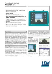
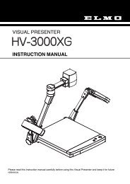
Disassembly and Reassembly<br />
Referring to Figure 1, disassemble the Meter as follows. A<br />
Phillips-head screwdriver and small flat-blade screwdriver<br />
are required.<br />
1. Remove the test leads and set the rotary knob to OFF.<br />
2. Remove the Phillips-head screws from the case bottom.<br />
3. Separate the case top from the case bottom.<br />
4. To replace the battery: lift the battery from the case<br />
bottom and insert a new 9V battery. Be sure the positive<br />
and negative battery posts are oriented correctly.<br />
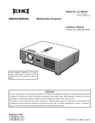
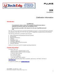
5. To remove the pca: insert a small, flat-blade<br />
screwdriver between the edge of the case top and the<br />
pca where shown in Figure 2. Gently unsnap a side of<br />
the case top from the pca. Repeat on the other side of<br />
the pca. Unsnap the case from the top of the pca last.<br />
Lift the pca from the case top by its edges. If the<br />
elastomeric contact strips for the switch assembly and<br />
LCD are stuck to the pca, remove them without touching<br />
the conductive edges.<br />
Note<br />
Before reinserting the pca, make sure that the<br />
rotary knob is in the OFF position.<br />
7. To reinsert the pca: Place the pca over the four screw<br />
posts in the case top, then press gently on the center of<br />
the pca while using the small flat-edge screwdriver to<br />
shoehorn the pca under the snap on a side of the case<br />
top. Repeat on the other side and the top.<br />
8. To remove the switch support, use a small, flat-blade<br />
screwdriver to gently unsnap the sides and top of the<br />
switch support from the snaps shown in Figure 2.<br />
9. The LCD, switch assembly, and elastomeric contact<br />
strips for the LCD and switch assembly are accessible<br />
and can be replaced as needed. Do not allow the LCD<br />
to get wet. Before installing a new LCD, make sure that<br />
all connector contact points are clean.<br />
Caution<br />
Do not touch the conductive edges of the<br />
elastomeric strips or the contacts on the switch<br />
assembly. If they are contaminated, clean them<br />
with isopropyl alcohol.<br />
9. Reassembling the Meter is the reverse of disassembling<br />
it. After the Meter is reassembled, execute the<br />
Performance Test to confirm that the Meter is working<br />
properly.<br />
Cleaning<br />
W Warning<br />
To avoid electrical shock, remove test leads<br />
and any input signals before cleaning.<br />
To clean the case, wipe it with a cloth lightly dampened with<br />
water and a mild detergent. Do not use abrasives, solvents,<br />
or alcohol.<br />
Recommended Test Equipment<br />
A list of recommended equipment for the performance test<br />
and calibration adjustment procedure is shown in Table 2.<br />
Equipment<br />
AC/DC Calibrator<br />
Decade Resistor<br />
Decade<br />
Capacitor<br />
Thermocouple<br />
Wire K-Type<br />
Temperature<br />
Probe<br />
Mercury<br />
Thermometer<br />
Table 2. Recommended Equipment<br />
Minimum<br />
Specification<br />
DC Voltage: 0 to<br />
600 V<br />
Accuracy: ±0.25%<br />
AC Voltage: 0 to<br />
600 V<br />
Accuracy: ±0.5%<br />
Frequency: 50 to<br />
400 Hz<br />
Resistance: 1.0 to<br />
40 MΩ<br />
Accuracy: ±0.25%<br />
Capacitance: 0 to<br />
1.000 µF<br />
Accuracy: ±0.5%<br />
Accuracy: Certified<br />
to ±0.2°C ambient<br />
0.02°C resolution<br />
0.05°F resolution<br />
Recommended<br />
Model<br />
5700A, or 5500A<br />
<strong>Fluke</strong> 5500A<br />
<strong>Fluke</strong> 5500A<br />
--- <strong>Fluke</strong> 80 PK-1<br />
<strong>Fluke</strong> 80T-150U<br />
Princo Model ASTM<br />
56C<br />
Princo Model ASTM<br />
56F<br />
Flask with cap --- Dewar Flask<br />
4
Recommended Test Equipment<br />
Decal<br />
Case, Top<br />
LCD<br />
Conn.<br />
Elastomeric<br />
Switch Assembly<br />
Conn.<br />
Elastomeric<br />
LCD to PCA<br />
Actuator, Switch<br />
Support, Switch Assembly<br />
Battery<br />
Shock Absorber<br />
Main PCA<br />
Case, Bottom<br />
Shield, Bottom<br />
Screw, THD Form, PH.P.STL,<br />
5-14 x .750<br />
Foot<br />
Figure 1. Model <strong>16</strong> Disassembled Unit<br />
ig3f.eps<br />
5
<strong>16</strong><br />
Multimeter with Temperature<br />
3<br />
2<br />
Snap<br />
Snaps<br />
Snap<br />
1<br />
Figure 2. Removing and Reinserting the Printed Circuit Assembly<br />
ig2f.eps<br />
6
Performance Test<br />
Performance Test<br />
W Warning<br />
To avoid electric shock, do not execute the<br />
performance tests procedures unless the<br />
Meter is fully assembled.<br />
To ensure that the Meter is working properly and performs<br />
to specifications, use the following procedures. If the Meter<br />
fails this test, it needs calibration adjustment or repair.<br />
Multimeter<br />
Note<br />
The following performance test is for all functions<br />
except for temperature. Temperature performance<br />
test follows this procedure.<br />
1. Referring to Table 3, put the Meter in the function and<br />
range shown for Test 1.<br />
2. Apply the input from the appropriate source to the [+]<br />
and COM jacks on the Meter. The reading on the<br />
display should be within the MINIMUM and MAXIMUM<br />
values shown in Table 3.<br />
3. Test the remaining functions and ranges. Repeat steps<br />
1 and 2 for test numbers 2 through 41.<br />
Temperature<br />
Note<br />
The performance test for the other functions must<br />
be done before this test is done.<br />
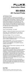
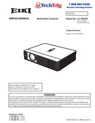
1. Connect the equipment as shown in Figure 3.<br />
2. Insert a mercury thermometer to the same depth as the<br />
thermocouple wire to verify that the ice bath<br />
temperature is 0.0°C.<br />
3. Short (or apply 0.0 mV) to the copper wires at the<br />
5700A Calibrator.<br />
4. Verify that the Meter reads 0.0°C ±0.8°C.<br />
5. If this test fails, reposition the thermocouple wires and<br />
mercury thermometer in the ice bath and repeat steps<br />
3 and 4. If the Meter continues to fail, use steps 6<br />
through 8 to verify the temperature performance tests.<br />
6. Remove the short applied in step 3.<br />
7. Set the 5700A using the input voltage shown in Table<br />
4. The reading on the display should be within the<br />
values shown in Table 4.<br />
8. Repeat step 3 to verify that the ice bath temperature is<br />
at 0.0°C ±0.3°C.<br />
<strong>Calibration</strong> Adjustments<br />
Perform the following calibration adjustment procedures if<br />
the Meter fails the performance test.<br />
Initial Steps<br />
1. Remove any input signals to the Meter.<br />
2. Remove the four screws on the back and separate the<br />
case bottom and case top.<br />
Notice that when you do so the battery remains in the<br />
case top and power to the Meter is disconnected.<br />
Note<br />
To avoid stretching or bending the battery<br />
contacts, connect leads to the base of the<br />
contacts as shown in Figure 4.<br />
3. Observing correct polarity, connect a 9 V battery to the<br />
battery contacts using easy hook jumpers or alligator<br />
clip leads (see Figure 4).<br />
Multimeter<br />
Note<br />
The following calibration adjustment<br />
procedure is for all functions except for<br />
temperature. Temperature calibration<br />
adjustment follows this procedure.<br />
1. Set the calibrator for 0 V dc. Put the Meter in the 4.000<br />
V dc range.<br />
2. Connect the calibrator to the [+] and COM jacks on the<br />
Meter.<br />
3. Apply an input of +4.000 V dc ±0.25%<br />
The Meter display should read between 3.<strong>99</strong>7-4.0<strong>03</strong> V.<br />
If it does not, adjust R4 as described in step 4 (see<br />
Figure 4).<br />
4. Adjust R4 (see Figure 4) so that the Meter display<br />
reads between 3.<strong>99</strong>7 and 4.0<strong>03</strong> V.<br />
5. Proceed to adjust the Temperature function.<br />
7
<strong>16</strong><br />
Multimeter with Temperature<br />
Table 3. Performance Tests<br />
Test No. Meter Range Input To Meter Switch<br />
Position<br />
1<br />
2<br />
3<br />
4<br />
5<br />
6<br />
7<br />
8<br />
9 1<br />
10<br />
11<br />
12<br />
13<br />
14<br />
15<br />
<strong>16</strong><br />
17<br />
18<br />
19<br />
20<br />
21<br />
22<br />
23<br />
24<br />
25<br />
26<br />
27<br />
28<br />
29 2<br />
30 2<br />
31<br />
32<br />
33<br />
34<br />
35<br />
36<br />
37<br />
38<br />
39<br />
40 4<br />
4.000 V ac<br />
4.000 V ac, MIN MAX<br />
4.000 V ac<br />
4.000 V ac<br />
4.000 V ac<br />
4.000 V ac<br />
40.00 V ac<br />
40.00 V ac<br />
400.0 V ac<br />
600 V ac<br />
4.000 V dc, MIN MAX<br />
4.000 V dc<br />
40.00 V dc<br />
400.0 V dc<br />
4.000 V dc<br />
40.00 V dc<br />
400.0 V dc<br />
600 V dc<br />
200 µA dc<br />
200 µA dc<br />
200 µA dc<br />
200 µA dc<br />
200 µA dc<br />
200 µA ac<br />
200 µA ac<br />
200 µA ac<br />
200 µA ac<br />
Continuity, Automatic Selection<br />
Continuity, Automatic Selection<br />
400.0 Ω<br />
400.0 Ω<br />
400.0 Ω<br />
4.000 kΩ<br />
40.00 kΩ<br />
400.0 kΩ<br />
4.000 MΩ<br />
40.00 MΩ<br />
Ω, Automatic Selection<br />
Continuity<br />
1.000 µF<br />
41 4 1.000 µF<br />
0 V<br />
0 V<br />
10 mV, 50 Hz<br />
10 mV, 400 Hz<br />
3.5 V, 50 Hz<br />
3.5 V, 400 Hz<br />
35 V, 50 Hz<br />
35 V, 400 Hz<br />
350 V, 80 Hz<br />
600 V, 400 Hz<br />
0 V<br />
0 V<br />
+20 mV dc<br />
-200 mV dc<br />
+3.5 V<br />
-35 V dc<br />
+100 V dc<br />
-600 V dc<br />
0.0 µA, dc<br />
10.0 µA, dc<br />
-10.0 µA, dc<br />
200.0 µA, dc<br />
-200.0 µA, dc<br />
40.0 µA, 50 Hz<br />
40.0 µA, 400 Hz<br />
200.0 µA, 50 Hz<br />
200.0 µA, 400 Hz<br />
+2 V dc 2<br />
+3.43 V dc 2<br />
-0.5 V dc 2<br />
0.0 Ω<br />
1.0 Ω<br />
350.0 Ω<br />
1.0 kΩ<br />
35 kΩ<br />
100 kΩ<br />
2.9 MΩ<br />
35 MΩ<br />
1.96 V dc<br />
0.0 µF<br />
0.95 µF<br />
Center<br />
Center<br />
Center<br />
Center<br />
Right<br />
Center<br />
Center<br />
Right<br />
Right<br />
Center<br />
Center<br />
Center<br />
Center<br />
Center<br />
Center<br />
Center<br />
Center<br />
Center<br />
Right<br />
Right<br />
Right<br />
Right<br />
Right<br />
Right<br />
Right<br />
Right<br />
Right<br />
Right<br />
Right<br />
Right<br />
Right<br />
Right<br />
Right<br />
Right<br />
Right<br />
Right<br />
Right<br />
Right<br />
Right<br />
Right<br />
Right<br />
Display<br />
Minimum<br />
0.000<br />
0.000<br />
0.007<br />
0.007<br />
3.430<br />
3.430<br />
34.30<br />
34.30<br />
343.0<br />
586<br />
-0.012<br />
-0.002<br />
00.01<br />
-000.3<br />
+3.466<br />
-35.33<br />
+<strong>99</strong>.0<br />
-606<br />
-0.2<br />
9.7<br />
-10.3<br />
197.8<br />
-202.2<br />
38.9<br />
38.9<br />
195.7<br />
195.7<br />
1.980<br />
3.397 3<br />
-0.507 3<br />
0.0<br />
0.8<br />
346.6<br />
0.<strong>99</strong>0<br />
34.67<br />
<strong>99</strong>.0<br />
2.873<br />
34.44<br />
1.940 3<br />
-0.001 µF<br />
0.930 µF<br />
Display<br />
Maximum<br />
0.0<strong>03</strong><br />
0.040<br />
0.013<br />
0.013<br />
3.570<br />
3.570<br />
35.70<br />
35.70<br />
357.0<br />
614<br />
0.012<br />
0.002<br />
00.<strong>03</strong><br />
-000.1<br />
+3.534<br />
-34.67<br />
+101.0<br />
-594<br />
0.2<br />
10.3<br />
-9.7<br />
202.2<br />
-197.8<br />
41.1<br />
41.1<br />
204.3<br />
204.3<br />
2.020<br />
3.463 3<br />
-0.493 3<br />
0.2<br />
1.2<br />
353.4<br />
1.010<br />
35.33<br />
101.0<br />
2.927<br />
35.56<br />
1.980 3<br />
0.001 µF<br />
0.970 µF<br />
1. In the Automatic Selection mode, the Meter uses a low-impedance thermistor (~2.5k for circuit protection and load testing<br />
(referred to as low-Z input circuitry). When using the 5100B, 5500A, or 5700A to drive the Meter with high voltages, avoid an<br />
overload/current limit condition by gradually stepping the voltage up (waiting two seconds between each step) from 90.0 V,<br />
120.0 V, 180.0 V, and 350.0 V at 80 Hz each step.<br />
2. Calibrator 50Ω divider override.<br />
3. The dc volts annunciator must be on.<br />
4. Conducting performance tests of the 400 Ω, 4 kΩ, 40 kΩ, and 1 µF ranges (tests no. 22, 23, 24, 25, 26, 31, and 32) verifies<br />
that the discrete and integrated circuitry needed to support the other capacitance ranges are working within specifications.<br />
Therefore, the tests indirectly verify that the Meter will meet specification in the 10 µF, 100 µF, 1000 µF, and 10,000 µF<br />
ranges.<br />
Table 4. Temperature Performance Tests<br />
Input Voltage<br />
Display Readings<br />
°C °F<br />
0.0 0.0 ± 0.8 32.0 ± 1.5<br />
0.919 mV 23.0 ± 1.0 73.4 ± 2.2<br />
4.095 mV 100.0 ± 1.8 212.0 ± 3.6<br />
8
+<br />
+<br />
<strong>Calibration</strong> Adjustments<br />
Temperature<br />
AK-80<br />
5700A<br />
Red<br />
Yellow<br />
Copper<br />
Ice Bath<br />
0<br />
Banana<br />
Plug<br />
Figure 3. Performance Test for Temperature<br />
ig6f.eps<br />
Clip to Base Contacts<br />
+<br />
+<br />
Input Receptacles<br />
Adjust R4 for 3.<strong>99</strong>7-4.0<strong>03</strong>V DC<br />
_<br />
+<br />
9V<br />
BATTERY<br />
Figure 4. <strong>Calibration</strong> Adjustment for DC Voltage<br />
ig1f.eps<br />
9
<strong>16</strong><br />
Multimeter with Temperature<br />
Temperature<br />
Note<br />
Adjust DC voltage (R4) before adjusting<br />
temperature (R38).<br />
The following describes three temperature calibration<br />
procedures:<br />
• Calibrating at room temperature. Use this procedure if<br />
it is not necessary to optimize the Meter’s performance.<br />
• Calibrating in an ice bath. Use this procedure to<br />
optimize the Meter’s performance at around 0.0°C.<br />
• Calibrating in a lag bath. Use this procedure to<br />
optimize the Meter’s performance at room temperature.<br />
Room Temperature <strong>Calibration</strong><br />
The following procedure allows you to make the calibration<br />
adjustment at room temperature.<br />
1. Allow the Meter to stabilize at room temperature. After<br />
the temperature stabilizes, do not touch the COM jack.<br />
2. Turn to temperature function and °C mode.<br />
3. Observing the correct polarity, connect a copper short<br />
across the input jacks of the Meter (see Figure 5).<br />
4. Using a temperature probe with the appropriate Meter<br />
(<strong>Fluke</strong> 45 or equivalent), measure the temperature of<br />
the COM input jack (see Figure 5). Be sure to place the<br />
probe on the COM closest to the pca.<br />
5. Adjust R38 so the Meter display is the same as the<br />
temperature probe reading.<br />
Ice Bath <strong>Calibration</strong><br />
The following procedure optimizes the Meter’s performance<br />
near 0°C (32°F) using a specific thermocouple.<br />
1. Put the Meter in the temperature function and °C<br />
mode.<br />
2. Insert a thermocouple in an ice bath (see<br />
Figure 6).<br />
3. Insert a mercury thermometer to the same depth as the<br />
thermocouple wire to verify that the ice bath<br />
temperature is 0.0°C .<br />
4. Connect the other end of the thermocouple wire to the<br />
Meter using a <strong>Fluke</strong> 80AK Adapter Plug (see Figure 6).<br />
Allow the instrument reading to settle.<br />
5. Adjust R38 so that the Meter display has the same<br />
reading of the ice bath temperature.<br />
Lag Bath <strong>Calibration</strong><br />
The following adjustment optimizes the Meter’s<br />
performance at room temperature using a specific<br />
thermocouple.<br />
1. Put the Meter in the temperature function and °C<br />
mode.<br />
2. Insert a thermocouple in a lag bath (see Figure 6).<br />
3. Insert a mercury thermometer to the same depth as the<br />
thermocouple wire to verify that the lag bath<br />
temperature is at room temperature<br />
4. Connect the other end of the thermocouple wire to the<br />
Meter using an 80AK Adapter Plug(see Figure 6).<br />
Allow the instrument reading to settle.<br />
5. Adjust R38 so that the Meter display has the same<br />
reading of the lag bath thermometer.<br />
Replacement Parts<br />
Replacement parts are listed in Table 4 and shown in<br />
Figure 1.<br />
Table 4. Replacement Parts<br />
Parts<br />
Part No.<br />
Window decal 617974<br />
Case, top 617966<br />
LCD 643541<br />
Connection elastomeric 867242<br />
Connection Elastomeric LCD to PCA 867247<br />
Switch assembly 618022<br />
Actuator, Switch 2<strong>03</strong>445<br />
Support, Switch Assembly 879<strong>03</strong>1<br />
Battery 696534<br />
Case, Bottom assembly 618097<br />
Screw, THD Form, PH.P.STL, 5014 x .750 832246<br />
Foot 885884<br />
10
Replacement Parts<br />
45<br />
DUAL DISPLAY MULTIMETER<br />
V<br />
10A<br />
1000V<br />
MAX<br />
750V<br />
COM<br />
m V<br />
FUSED<br />
! CAL<br />
ENABLE<br />
100<br />
mA<br />
500mA<br />
F 250V<br />
V<br />
A<br />
REL<br />
REF#<br />
dB<br />
REF<br />
2ND<br />
LOCAL<br />
ALL INPUTS<br />
1kV MAX<br />
V<br />
A<br />
FREQ<br />
AUTO<br />
COMP<br />
HI<br />
LO<br />
HOLD MN MX RATE<br />
THRESH ADDR BAUD<br />
POWER<br />
80T-150U<br />
Clip to Base Contacts<br />
+<br />
+<br />
9V<br />
R38<br />
BATTERY<br />
+<br />
_<br />
Figure 5. <strong>Calibration</strong> Adjustment for Temperature Using the 80T-150U<br />
ig4f.eps<br />
Thermometer<br />
Ice or Lag Bath<br />
Clip to Base Contacts<br />
+<br />
80AK +<br />
+<br />
R38<br />
9V<br />
BATTERY<br />
+<br />
_<br />
Thermocouple<br />
Figure 6. <strong>Calibration</strong> Adjustment for Temperature Using an Ice or Lag Bath<br />
ig5f.eps<br />
11
<strong>16</strong><br />
Multimeter with Temperature<br />
12