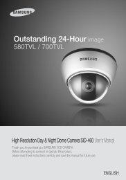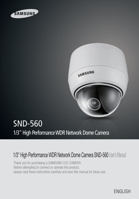
SND-560
SND-560
SND-560

You also want an ePaper? Increase the reach of your titles
YUMPU automatically turns print PDFs into web optimized ePapers that Google loves.
<strong>SND</strong>-<strong>560</strong><br />
1/3" High Performance WDR Network Dome Camera<br />
1/3" High Performance WDR Network Dome Camera <strong>SND</strong>-<strong>560</strong> User’s Manual<br />
Thank you for purchasing a SAMSUNG CCD CAMERA.<br />
Before attempting to connect or operate this product,<br />
please read these instructions carefully and save this manual for future use.<br />
ENGLISH
A brand that is integrated into Samsung's network products,<br />
stands for a convenient world (Polis) made safe (Police) through Samsung's superior<br />
network performance(Internet protocol). With<br />
products ' clear digital<br />
images transmitted over the internet, real-time monitoring is possible anywhere with<br />
an internet connection. Easy remote control functions and the use of existing<br />
networks minimize installation costs. With<br />
experience a world of<br />
convenience connected anytime, anywhere.<br />
■ Preface<br />
Thanks for purchasing of <strong>SND</strong>-<strong>560</strong> camera.<br />
This is a user instruction manual for high resolution WDR network camera and the<br />
product mentioned here designates the high resolution WDR network camera.<br />
The user who installs and operates the product shall be aware of this manual and<br />
other manuals referenced by this manual before the installation and operation and<br />
use properly.<br />
This manual and the software and hardware explained here are protected by<br />
copyright law.<br />
So the copy, reprint and translation to other languages of a part of or all contents of<br />
this user manual without permission of SamsungTechwin Co., LTD are not allowed<br />
except for the copy for general use within the scope of copyright law.<br />
■ Note to User<br />
This machine’s electromagnetic waves have been registered as suitable for<br />
business purposes; the retailer and consumer should be aware of this registration.<br />
If in the case of wrongful purchases, please exchange the product for a home use<br />
product.<br />
The lightning flash with an arrowhead symbol, within an equilateral triangle is<br />
intended to alert the user to the presence of uninsulated “dangerous voltage”<br />
within the product's enclosure that may be of sufficient magnitude to constitute<br />
a risk of electric shock to persons.<br />
The exclamation point within an equilateral triangle is intended to alert the user<br />
to the presence of important operating and maintenance (servicing) instructions<br />
in the literature accompanying the appliance.<br />
INFORMATION -This equipment has been tested and found to comply with limits<br />
for a Class A digital device, pursuant to part 15 of the FCC Rules. These limits are<br />
designed to provide reasonable protection against harmful interference when the<br />
equipment is operated in a commercial environment. This equipment generates,<br />
uses, and can radiate radio frequency energy and, if not installed and used in<br />
accordance with the instruction manual, may cause harmful interference to radio<br />
communications.<br />
Operation of this equipment in a residential area is likely to cause harmful<br />
interference in which case the user will be required to correct the interference at<br />
his own expense.<br />
WARNING - Changes or modifications not expressly approved by the manufacturer<br />
could void the user’s authority to operate the equipment.<br />
WARNING - To prevent electric shock and risk of fire hazards:<br />
◆ Do NOT use power sources other than that specified.<br />
◆ Do NOT expose this appliance to rain or moisture.<br />
This installation should be made by a qualified service person and<br />
should conform to all local codes.<br />
NETWORK CAMERA<br />
2 User’s Manual<br />
NETWORK CAMERA 3 User’s Manual
Contents Contents<br />
■Preface… ……………………………………………………………………………………… 2…<br />
■Note to User…………………………………………………………………………………… 2<br />
Contents …………………………………………………………………………… 4<br />
■Product Warranty and Limitations… ………………………………………………………… 6…<br />
■Warning Symbols… …………………………………………………………………………… 6<br />
Precautions… ……………………………………………………………………… 7<br />
Ch1. Overview……………………………………………………………………… 8<br />
1.1. <strong>SND</strong>-<strong>560</strong> Network Camera Introduction …………………………………… 8…<br />
1.2. Features……………………………………………………………………………… 9<br />
Ch2. Production Description………………………………………………… 10<br />
2.1. Components and Accessories… ……………………………………………… 10…<br />
2.2. Section names and functions ………………………………………………… 11 …<br />
2.3. Recommended PC specifications……………………………………………… 12<br />
Ch3. Installation and Network Setup……………………………………… 12<br />
3.1. Camera Installation……………………………………………………………… 12…<br />
… … 3.1.1. When installing on a adapter plate…………………………………… 13…<br />
3.2. Adjust the panning and tilting, rotating while watching the monitor………… 1 4 …<br />
3.3. Connecting to Monitor… ………………………………………………………… 15 …<br />
3.4. Connecting to Power……………………………………………………………… 1 6 …<br />
3.5. Connection to External Control Connector ………………………………… 17 …<br />
3.6. Network configuration and connection method using Web page… ……… 20<br />
Ch4. How to Use Web Viewer……………………………………………… 24<br />
4.1. How to Use Web Viewer… ……………………………………………………… 24 …<br />
… … 4.1.1. Login… ……………………………………………………………………… 24…<br />
… … 4.1.2. Web Viewer screen……………………………………………………… 25…<br />
4.2. Using Administration page……………………………………………………… 30 …<br />
… … 4.2.1. Initialization Screen after Connecting (Basic Screen)… ………… 30…<br />
… … 4.2.2. Live…………………………………………………………………………… 31…<br />
… … 4.2.3. Basic… ……………………………………………………………………… 32…<br />
… … 4.2.4. Network……………………………………………………………………… 34…<br />
… … 4.2.5. Video Analytics…………………………………………………………… 46…<br />
… … 4.2.6. Privacy… …………………………………………………………………… 47…<br />
… … 4.2.7. Record (Using the SD Memory)………………………………………… 48…<br />
… … 4.2.8. User…………………………………………………………………………… 50…<br />
… … 4.2.9. Motion Detection………………………………………………………… 52…<br />
… … 4.2.10. Alarm/Sensor…………………………………………………………… 53…<br />
… … 4.2.11. Time………………………………………………………………………… 56…<br />
… … 4.2.12. LOG… ……………………………………………………………………… 57…<br />
… … 4.2.13. Upgrade… ………………………………………………………………… 58…<br />
… … 4.2.14. System Reboot…………………………………………………………… 59<br />
Ch5. How to Operate Camera………………………………………………… 60<br />
5.1. Setup MENU………………………………………………………………………… 60…<br />
5.2. How to Set Up Functions………………………………………………………… 61…<br />
… … 5.2.1. LENS… ……………………………………………………………………… 62…<br />
… … 5.2.2. EXPOSURE………………………………………………………………… 62 …<br />
… … 5.2.3. WHITE BALALACE (WHITE BAL.)……………………………………… 64 …<br />
… … 5.2.4. BACKLIGHT… ……………………………………………………………… 65…<br />
… … 5.2.5. SSNR… ……………………………………………………………………… 67 …<br />
… … 5.2.6. DAY/NIGHT………………………………………………………………… 67 …<br />
… … 5.2.7. IMAGE ADJ………………………………………………………………… 69…<br />
… … 5.2.8. SPECIAL……………………………………………………………………… 70…<br />
… … 5.2.9. EXIT…………………………………………………………………………… 74<br />
Ch6. Troubleshooting…………………………………………………………… 75<br />
Specifications… ………………………………………………………………………… 77…<br />
Dimension………………………………………………………………………………… 79<br />
Notes<br />
• If you refer to the enclosed Quick guide and the Manual in the CD, you can learn how to<br />
use Network Manager.<br />
NETWORK CAMERA<br />
4 User’s Manual<br />
NETWORK CAMERA 5 User’s Manual
Samsung Techwin cares for the environment at all product manufacturing stages<br />
to preserve the environment, and is taking a number of steps to provide<br />
customers with more environment-friendly products.The Eco mark represents<br />
Samsung Techwin’s will to create environment-friendly products, and indicates<br />
that the product satisfies the EU RoHS Directive.<br />
■ Product Warranty and Limitations<br />
The manufacturers of this product do not take any responsibility for this product;<br />
therefore, the manufacturer does not authorize the third-party, but allows that retailer is<br />
responsible.<br />
The product warranty does not extend to cover accidents, negligence, abuse, or wrongful<br />
use for the whole or any part of the product. Additionally, the manufacturer does not<br />
provide warranty for any additional parts or affiliations.<br />
The warranty does not extend to malfunction in these areas.<br />
·Malfunction due to user’s negligence<br />
·Dismantlement or replacement by the user<br />
·Connection to alternate power source<br />
·Malfunction due to natural disasters (fire, flood, tsunami, etc.)<br />
·Replacement due to wear and tear<br />
·Instability of network<br />
■ Warning Symbols<br />
Before attempting to connect or operate this product,<br />
please read these instructions carefully and save this manual for future use.<br />
Danger :<br />
Misuse or wrongful operation of the product may result in death, injury or bring about other<br />
fatal results. It indicates absolute caution when operating.<br />
Caution :<br />
Misuse or wrongful operation of the product may result in slight injury or<br />
damage to the product. It indicates caution when operating.<br />
Note :<br />
Indication that the user needs to be aware of certain matters, or will find matters<br />
helpful in operating the product.<br />
Danger<br />
·Random replacement of built-in battery by other types of batteries may cause<br />
explosion. The battery shall be replaced by the same battery. The used batteries shall<br />
be disposed carefully because they can cause environment pollutions.<br />
·The battery shall be replaced by the same battery.<br />
·The used batteries shall be disposed carefully because they can cause environment<br />
pollutions.<br />
·The lithium battery incorporated in this product is not user replaceable. Replacement<br />
of the lithium battery will be done by a trained technician.<br />
·For information on its replacement, please contact your service provider.<br />
Do not install under extreme<br />
temperature conditions.<br />
Use only under temperature conditions between<br />
-10ºC and +50ºC. Provide good ventilation when<br />
using in high temperature conditions.<br />
Do not install under unstable<br />
lighting conditions.<br />
Severe lighting changes or flickering may hinder<br />
normal camera operation.<br />
Do not drop the camera or subject<br />
it to physical shock.<br />
May cause a product malfunction.<br />
Precautions<br />
Do not install in high humidity<br />
environment.<br />
May lower image quality.<br />
Avoid touching the camera lens.<br />
The lens is the most important component of<br />
the camera. Be careful not to smear it with<br />
fingerprints.<br />
Never keep the camera face to<br />
strong light directly.<br />
May damage the CCD.<br />
NETWORK CAMERA<br />
6 User’s Manual<br />
NETWORK CAMERA 7 User’s Manual
Precautions<br />
Do not expose the camera to<br />
radioactivity.<br />
1.2. Features<br />
If it is exposed to radioactivity, For heated CCD, it<br />
will be out of order.<br />
Notes<br />
• Exposure to a spotlight or an object emitting strong light may cause smear or blooming.<br />
• Ensure that the power source complies with normal specifications before supplying it to<br />
the camera.<br />
Ch1. Overview<br />
1.1. <strong>SND</strong>-<strong>560</strong> Network Camera Introduction<br />
The <strong>SND</strong>-<strong>560</strong> is a high-tech network camera that uses MPEG-4 codec technology<br />
to allow high compression rates and clear picture quality by allowing for high<br />
frame rates to be transmitted through the network.<br />
By using the network, remote connection, monitoring, and control is possible<br />
from any location for simple use; additionally, set-up requires only a network.<br />
The <strong>SND</strong>-<strong>560</strong> Network Camera utilizes embedded software solutions (Embedded<br />
Web Server, Embedded Streaming Server, Network Protocol) developed by<br />
SamsungTechwin, and guarantees performance and safety while offering<br />
various solutions through Internet integration.<br />
High Resolution<br />
The horizontal resolution of <strong>560</strong>TV lines at color mode<br />
and 700TV lines at BW mode can be achieved by<br />
using a high density SONY CCD having double speed<br />
410,000 pixels, which provides clean, noiseless and<br />
reliable pictures.<br />
Multi-channel Real-time image<br />
encoding<br />
Single Chip MPEG4 and JPEG codec enables real time<br />
image encoding and transmission through multichannel<br />
of classified resolution of D1/CIF/QCIF.<br />
Wide Dynamic Range (WDR)<br />
The main function of the Wide Dynamic Range (WDR)<br />
is to accumulate the scope of contrast between the<br />
brightest and darkest points in the picture. WDR<br />
employing SV-IV chipset provides prominent back<br />
light compensation effect in high-contrast<br />
environment.<br />
High sensitivity against low illumination<br />
Diagonal 6 mm (1/3”) CCD of enhanced sensitivity<br />
and DSP chipset catch contour and color of objectives<br />
only with starlight illumination in the dark, which<br />
provides reliable outdoor surveillance performance.<br />
- 0.001Lux (Lux for color mode)<br />
- 0.00004Lux (Lux for black and white mode)<br />
DAY & NIGHT fuction<br />
Day & night function and Sens-up function by ICR (IR<br />
Cut-Filter Removal) operation produce high quality<br />
images for 24 hours.<br />
Sens-Up function delays exposing time to improve<br />
CCD sensitivity.<br />
Day & Night function allows users choose color<br />
mode or BW mode depending upon illumination.<br />
PoE (Power Over Ethernet)<br />
PoE function is to supply power through the LAN<br />
cable together with data transmission without power<br />
cable for user convenience.<br />
DIS (Digital Image Stabilizer)<br />
DIS (Digital Image Stabilizer) function compensates<br />
camera shaking to obtain clear-cut images.<br />
SD Memory function<br />
SD Memory function is to memorize an event at the<br />
SD Memory when it activated.<br />
Privacy function<br />
Privacy function is to determine surveillance area not<br />
to display on the monitor for privacy protection.<br />
NETWORK CAMERA<br />
8 User’s Manual<br />
NETWORK CAMERA 9 User’s Manual
Ch1. Overview<br />
SSNR (Samsung Super Noise<br />
Reduction)<br />
Samsung’s high performance DSP chipset SV-IV<br />
reduces GAIN variance effectively to deliver clean and<br />
clear-cut images.<br />
Combination of motion detection and<br />
alarm<br />
Combination of motion detection, video analytics and<br />
alarm enables still image storage in the SD Memory<br />
or transmission of still image via email or FTP.<br />
2.2. Section names and functions<br />
❿<br />
1<br />
⓫<br />
2<br />
3<br />
High data compression ratio<br />
Real time interactive audio Transmission<br />
High compression in MPEG-4 provides fast<br />
transmission and relatively high volume transmission<br />
of frame in the same network band.<br />
Additional functions<br />
SENS-UP, Mirror, SHARPNESS, SYNC choice (INT/LL)<br />
5<br />
4<br />
6 7 8 9<br />
Ch2. Production Description<br />
2.1. Components and Accessories<br />
❶ 2<br />
5<br />
6 7<br />
3 4<br />
1 <strong>SND</strong>-<strong>560</strong> 2 User’s Manual / CD / Quick Guide<br />
3 DC 12V Adaptor / Power Cord 4 Cross Cable<br />
5 M4 Tapping Screw 3EA 6 Installation Video Output Cable<br />
7 Installation Template<br />
❶ Pan Base : control panning angle of camera<br />
2 Rotate Base : control rotating angle of camera<br />
3 x3.6, 2.8 - 10.0mm (F1.2)<br />
4 Rotate Base Holding Screw : fix rotated position<br />
5 Pan Base Holding Screws (Color : black) : fix panned position<br />
6 Audio Input/Output Jack 7 Alarm Jack<br />
8 Ethernet 9 Power<br />
❿ Shield Case<br />
⓫ Dome Cover<br />
Notes<br />
• When you connect <strong>SND</strong>-<strong>560</strong> network camera to the PoE apparatus, the voltage<br />
transferred via LAN cable may be abnormally high. Please contact to our distributor for<br />
installation or dismantling PoE system.<br />
NETWORK CAMERA<br />
10 User’s Manual<br />
NETWORK CAMERA 11 User’s Manual
Ch2. Production Description<br />
2.3. Recommended PC specifications<br />
Items<br />
Specifications<br />
CPU<br />
Intel core2 duo E4300 or higher processor<br />
Main Memory<br />
2GB or higher RAM<br />
VGA<br />
256M or higher recommended<br />
OS Window 2000, XP, 2003<br />
Web Browser<br />
Internet explorer 5.5 or higher<br />
Resolution<br />
1024*768 or higher<br />
Network<br />
10/100 Base-T Ethernet<br />
DirectX<br />
9.0C or higher<br />
Ch3. Installation and Network Setup<br />
3.1. Camera Installation<br />
1) Separate the dome cover by counterclockwise rotation.<br />
2) Separate the shield case by pulling from the camera body.<br />
Latch<br />
Main Body<br />
(Camera)<br />
Notes<br />
• The installation should be done by qualified service personnel or sysytem installers.<br />
• If the ceiling material is not strong enough to hold the installation screws, the camera may<br />
fall off. Reinforce the ceiling as needed.<br />
3.1.1 When installing on a adapter plate<br />
adapter<br />
plate<br />
CAMERA<br />
An arrow for installing directions<br />
1 Place the installation template on the installation<br />
surface.<br />
2 Bore three holes signed on the installation<br />
Template through the installation surface and<br />
place the camera body and fix it with the M4<br />
tapping screws.<br />
3 When placing the camera body on the plate,<br />
make sure the power and the ETHERNET cables<br />
pass through their respective designated<br />
holes.(When placing the cable through its<br />
side, thread it through the hole at the bottom.)<br />
4 After installation and adjustment of the<br />
camera are complete, secure the dome cover<br />
by turning it clockwise.<br />
[Figure-1]<br />
Locking direction<br />
Unlocking direction<br />
(Counterclockwise)<br />
* To install the dome cover on the camera body, turn the<br />
latches in locking direction as shown in the figure 1.<br />
Shield Case<br />
Locking direction<br />
(Clockwise)<br />
Dome cover<br />
Unlocking<br />
direction<br />
Dome cover<br />
Locking<br />
direction<br />
NETWORK CAMERA<br />
12 User’s Manual<br />
NETWORK CAMERA 13 User’s Manual
Ch3. Installation and Network Setup<br />
3.2. Adjust the panning and tilting, rotating while watching the monitor<br />
3.3. Connecting to Monitor<br />
Connect the VIDEO-OUT jack to the VIDEO-IN jack of monitor.<br />
145˚<br />
195˚<br />
73˚<br />
170˚<br />
Tilt Base<br />
Rotate Base<br />
Pan Base<br />
-170˚<br />
<strong>SND</strong>-<strong>560</strong> Network Camera<br />
Monitor<br />
1) You can adjust camera to any direction by using Pan, Tilt, Rotate mechanism.<br />
• Pan Base moves by 170˚ to each side direction and 340˚ on the whole.<br />
• Tilt Base covers total 146˚ angle(73˚ to each side).<br />
• Angle range of Rotate Base is the same as that of Pan Base. But One side range is 195˚<br />
and another is 145˚<br />
2) Methods of adjustment<br />
• The case of wall installation<br />
1 After mounting the camera on a wall, adjusting the panning angle so that the camera can<br />
face the direction to monitor when tilting.<br />
2 And then adjust the tilting angle by rotating the tilt base.<br />
3 Loosen the rotate base hold screw and adjust rotate base for the best monitoring.<br />
4 Tighten the rotate base hold screw.<br />
• The case of ceiling installation<br />
1 After mounting the camera on a ceiling, adjusting the panning angle for better monitoring<br />
area by rotating the pan base.<br />
2 And then adjust the tilting angle by rotating the tilt base.<br />
3 Loosen the rotate base hold screw and adjust rotate base for the best monitoring.<br />
4 Tighten the rotate base hold screw.<br />
• As the connecting method varies with the instruments, refer to the manual supplied with the<br />
instrument.<br />
• If necessary, you can connect the monitor to the REMOTE jack on the body of your camera.<br />
• Only connect the cable when the power is turned off.<br />
Notes<br />
• This product is the network camera which transmits video through network, video output<br />
terminal is for installation and used to determine imaging range when installing the product.<br />
• Please make sure that the video output terminal of this product is not connected to any<br />
recording equipment as this can cause problems.<br />
NETWORK CAMERA<br />
14 User’s Manual<br />
NETWORK CAMERA 15 User’s Manual
Ch3. Installation and Network Setup<br />
3.4. Connecting to Power<br />
■ AC/DC Power<br />
Both of AC24V and DC12V can be used for the input power of this product.<br />
When using other adaptor not the adaptor (DC12V/4A) provided by the company, make sure<br />
that the specification is over AC 24V/1A or DC12V/2A.<br />
■ AC/DC Combined use<br />
■ PoE(Power Over Ethernet)<br />
POE(Power Over Ethernet)is the function of LAN related devices, which supports data and<br />
power simultaneously with only connection of LAN cable without separate power input cable<br />
installation for power excitation to the product.<br />
When connecting camera to PoE device, please connect to the device complying with PoE<br />
(IEEE802.3af) specifications. In case non-standard product is used, it may cause performance<br />
degradation or trouble.<br />
3.5. Connection to External Control Connector<br />
The input order of terminal from left is Alarm input/Alarm output/Ground.<br />
When connecting cable, push stripped part of electric wire in while pushing quadrangle button<br />
and take hands off from the button then the wire will be fixed.<br />
When the resistance value of copper wire is at [20°C(68°F)]<br />
Copper wire size (AWG) #24(0.22mm 2 ) #22(0.33mm 2 ) #20(0.52mm 2 ) #18(0.83mm 2 )<br />
Resistance (Ω/m) 0.078 0.050 0.030 0.018<br />
Voltage Drop (V/m) 0.028 0.018 0.011 0.006<br />
❶ Alarm Input<br />
2 Alarm Output<br />
3 Ground<br />
• As shown in the table above, voltage decreases as the wire gets longer.<br />
Therefore use of an excessively long adaptor output line for connection to the<br />
camera may affect the performance of the camera.<br />
Standard voltage for camera operation : DC 12V±10%, AC 24V±10%<br />
There may be some deviation in voltage drop depending on the type of wire and the manufacturer.<br />
Notes<br />
• In case PoE and power adaptor are connected to camera simultaneously, the power<br />
authorized first by the product is used.<br />
NETWORK CAMERA<br />
16 User’s Manual<br />
NETWORK CAMERA 17 User’s Manual
Ch3. Installation and Network Setup<br />
■ Connecting Alarm Input<br />
This is the input terminal for external alarm signal, use it by connecting as following.<br />
■ Connecting Alarm output<br />
This is the output terminal for external alarm signal, use it by connecting as following.<br />
Sensor Input<br />
3.3V<br />
120Ω<br />
10KΩ<br />
5.1KΩ<br />
Camera<br />
Internal<br />
Alarm In<br />
Sensor<br />
CMOS Output<br />
2.2KΩ<br />
10KΩ<br />
Open Collector<br />
Alarm Out<br />
GND<br />
Relay<br />
Relay<br />
Output<br />
Relay<br />
Power<br />
GND<br />
• In case of selecting Normal Open at setup menu :<br />
In case of contact type, it is short and in case of active type, sensor input acts at “LOW” level.<br />
• In case of selecting Normal Close at setup menu :<br />
In case of contact type, it is open and in case of active type, sensor input acts at high<br />
impedance status(open collector).<br />
• Alarm output part is Open Collector structure and can be composed by using relay. Rated<br />
maximum value is DC +24V, 100 mA.<br />
NETWORK CAMERA<br />
18 User’s Manual<br />
NETWORK CAMERA 19 User’s Manual
Ch3. Installation and Network Setup<br />
3.6. Network configuration and connection method using Web page<br />
Use when there is one <strong>SND</strong>-<strong>560</strong> network camera to be installed.<br />
1. Please connect user’s PC to <strong>SND</strong>-<strong>560</strong> network camera using cross cable.<br />
2. Please launch a Web browser on user’s PC and enter [192.168.1.100] in the URL address<br />
field and push button. Connect to Webviewer login window of <strong>SND</strong>-<strong>560</strong> network<br />
camera.<br />
Note<br />
3. Please login with administrator’s authorization and move to ‘Network’ page.(Default value<br />
for administrator login is ID: admin, PW:11111111)<br />
• After pressing internet protocol (TCP/IP)<br />
properties, press the ‘advanced’ button<br />
to go into advanced configurations.<br />
• Add with 192.168.1.XXX.<br />
Notes<br />
• 192.168.1.100 is the IP address for the camera and will be unavailable as an internal IP<br />
address.<br />
Note • Default value is ID: admin, PW: 11111111<br />
NETWORK CAMERA<br />
20 User’s Manual<br />
NETWORK CAMERA 21 User’s Manual
Ch3. Installation and Network Setup<br />
1 LAN / xDSL/ DHCP Configuration<br />
4. Please configure according to the network environment where <strong>SND</strong>-<strong>560</strong> network camera<br />
will be installed and push button to save the configuration.<br />
Item<br />
LAN Use<br />
xDSL<br />
DHCP<br />
2 Port Configuration<br />
Description<br />
When network product is connected to normal local LAN or when<br />
connected to static IP, the network data to be allotted to the IP is<br />
configured.<br />
When using xDSL dynamic IP, enter the ID and PW.<br />
When automatically receiving IP through DHCP server, the DHCP<br />
functions are activated. ‘DHCP’ is used in the LAN environment where<br />
the DHCP is activated. Generally, for mid/large scale, DHCP servers are<br />
operated through LAN and for small-scales, IP sharers use DHCP<br />
functions.<br />
Item<br />
Port Setting<br />
Note<br />
Description<br />
The connection port and http, ftp port configurations can be set here<br />
and the DDNS use can be checked.<br />
• Use DDNS changes its IP address every time the user attempts to connect to the<br />
ISP and when the product is connected to a cable modem or xDSL modem. In this<br />
case, the user cannot know the changed IP address. When a product that uses<br />
dynamic IP is registered on the DDNS server, when wishing to connect to the<br />
product, the changed IP address can be easily recognized. Register the product in<br />
the DDNS server in order to register the IP address in the DDNS server. Enable the<br />
“Use DDNS” option and enter the submitted ID and password into the server.<br />
NETWORK CAMERA<br />
22 User’s Manual<br />
NETWORK CAMERA 23 User’s Manual
Ch4. How to Use Web Viewer<br />
4.1. How to Use Web Viewer<br />
4.1.1. Login<br />
To connect the login page, enter IP address of the camera on a internet Web browser and push<br />
enter key.<br />
4.1.2. Web Viewer screen<br />
Web Viewer screen is composed of menu area for camera/video configuration and screen area<br />
for displaying input video from camera.<br />
<strong>SND</strong><strong>560</strong><br />
Enter user ID and password and push button, then it move to related Web page.<br />
(Default value is ID: admin, PW: 11111111 ) If you click button, it move to WebViewer<br />
page under the Guest authenticated status. In this case, administrator should permit the Guest<br />
connection.<br />
■ Controls<br />
Video Analytics (Convert to Video Analytics mode)<br />
This button is activated when the Video Analytics Enable option is selected on the<br />
Video Analytics page. A menu arrangement of the Analytics mode is different with<br />
one of the Control mode.<br />
Note<br />
• If you logged in first as a administrator mode, please change the password<br />
of administrator. It can prevent from other users connection to<br />
administration page.<br />
NETWORK CAMERA<br />
24 User’s Manual<br />
NETWORK CAMERA 25 User’s Manual
Ch4. How to Use Web Viewer<br />
RESET (Displayed when the Video Analytics mode is on)<br />
This sets the current screen image to the background.<br />
Flip Image<br />
Turns the screen upside down.<br />
<strong>SND</strong><strong>560</strong><br />
<strong>SND</strong><strong>560</strong><br />
<strong>SND</strong><strong>560</strong><br />
Stretch Image<br />
Expands the screen to the size of D1 when selecting CIF and QCIF for resolution.<br />
<strong>SND</strong><strong>560</strong><br />
Alpha branding (Displayed when the Video Analytics mode is on)<br />
Makes changed parts appear half-transparent.<br />
<strong>SND</strong><strong>560</strong><br />
Notes<br />
• It is not recommended to use alpha branding in the low specification system.<br />
Save Image<br />
Saves the channel screen as a JPEG file.<br />
Compression<br />
Video compression mode (the mode of compressing<br />
video)<br />
- MPEG, JPEG<br />
Resolution<br />
Video resolution (the size of video screen transmitted)<br />
- NTSC : D1(704x480), CIF(352x240), QCIF(176x120)<br />
- PAL : D1(704x576), CIF(352x288), QCIF(176x144)<br />
Frame Rate - Setting on the Basic page<br />
The number of maximum video frame transmitted for<br />
each second.<br />
NETWORK CAMERA<br />
26 User’s Manual<br />
NETWORK CAMERA 27 User’s Manual
Ch4. How to Use Web Viewer<br />
How to Use the Camera<br />
- 1, 5, 10, 15, 20, 25, 30<br />
Quality - Setting on the Basic page<br />
Video quality<br />
- Very High, High, Normal, Low, Very Low<br />
<strong>SND</strong><strong>560</strong><br />
Pause : Stops video for a while.<br />
OSD : Displays related information.<br />
Camera OSD is displayed<br />
Day&Night : Day&Night configuration function (Color, B/W configuration)<br />
<strong>SND</strong><strong>560</strong><br />
■ Instruction for Camera OSD control button<br />
Displays the title<br />
, button : Moves selection displaying arrows up and down on camera OSD menu.<br />
, button : Changes configuration of selected field on camera OSD menu.<br />
button : Displays camera OSD or moves to upper/lower menu of selected field.<br />
button : Terminates camera OSD.<br />
Removes the title<br />
* For configuring the function and detail operating method of <strong>SND</strong>-<strong>560</strong> network camera, refer ‘ch5.<br />
How to Operate Camera’.<br />
Camera Setup : Displays OSD control button of camera.<br />
NETWORK CAMERA<br />
28 User’s Manual<br />
NETWORK CAMERA 29 User’s Manual
Ch4. How to Use Web Viewer<br />
4.2. Using Administration page<br />
4.2.1. Initialization Screen after Connecting (Basic Screen)<br />
When connection is successful, the below screen will be displayed.<br />
4.2.2. Live<br />
Please Move to Web Viewer page<br />
[Web Viewer live screen]<br />
NETWORK CAMERA<br />
30 User’s Manual<br />
NETWORK CAMERA 31 User’s Manual
Ch4. How to Use Web Viewer<br />
4.2.3. Basic<br />
Setup menu for basic configuration.<br />
■ Video/Audio Setup<br />
Item<br />
Video Format<br />
Description<br />
If you select the type of camera installed (NTSC or PAL), you can<br />
choose the size of the view on the camera.<br />
Item<br />
Compression Type<br />
Initial Resolution<br />
Video Quality<br />
Video FrameRate<br />
Video Channel<br />
Audio-In Channel<br />
Audio-Out<br />
Channel<br />
Max User Count<br />
Microphone<br />
Sensitivity<br />
Description<br />
Video compression type (This defines how the video is<br />
compressed.)<br />
Defines the size of the live screen view.<br />
Selects the video quality. You can still view uninterrupted video<br />
with the quality reduced if you use a low speed Internet<br />
connection.<br />
Defines how many frames the camera will transfer per second.<br />
Defines what video channel will be used by the camera.<br />
Determines whether to use an audio input channel for the camera.<br />
Determines whether to use an audio output channel for the<br />
camera.<br />
Specifies how many users (up to 20) can connect to the camera via<br />
the network.<br />
Audio Amplifier<br />
You need to set the sensitivity to Low with an amplifier-equipped<br />
microphone and to High with an amplifier-free Microphone (set it<br />
to low for line-in signals).<br />
■ Product Information<br />
Item<br />
Model<br />
Mac Address<br />
Camera Name<br />
Location<br />
Description<br />
Memo<br />
Description<br />
Describe camera model.<br />
Describe MAC address of camera.<br />
Name each camera to identify multi cameras on the network.<br />
Describe each camera location.<br />
Describe more information of camera.<br />
Describe contact number of the camera operator.<br />
NETWORK CAMERA<br />
32 User’s Manual<br />
NETWORK CAMERA 33 User’s Manual
Ch4. How to Use Web Viewer<br />
4.2.4. Network<br />
Network Configuration menu.<br />
■ Network Configuration<br />
You can select LAN interface for static IP configuration, xDSL modem and DHCP for cable<br />
modem.<br />
LAN<br />
xDSL<br />
DHCP<br />
Item<br />
Description<br />
Configure network assignment information of a camera connected<br />
to the local area network or to the static IP of xDSL modem.<br />
For dynamic IP of xDSL, enter ID and password of xDSL in the<br />
username box and password box.<br />
For IP router or cable modem interface, select DHCP.<br />
■ Port/DDNS Configuration<br />
Item<br />
Connection Port<br />
HTTP Port/<br />
FTP Port<br />
Use DDNS<br />
Description<br />
Connection port is to control communication with camera. (Default<br />
: 4000)<br />
HTTP /FTP port is to access to the camera web page or to use FTP<br />
function. (Default : http=80, ftp=21)<br />
Determine use of DDNS server. DDNS allows you to connect to the<br />
server transforming dynamic IP.<br />
■ Continuous Jpeg Image Transmission<br />
Item<br />
Enable<br />
FrameRate<br />
Server Name<br />
Home Directory<br />
User ID<br />
User Password<br />
Description<br />
Determine use of Continuous JPEG Image Transmission function.<br />
Determine frame rate (frame per seconds) to send out.<br />
Enter domain name or IP address of the FTP server.<br />
Configure home directory to store assigned data of the FTP server.<br />
Enter ID to access to the FTP server.<br />
Enter Password to access to the FTP server.<br />
NETWORK CAMERA<br />
34 User’s Manual<br />
NETWORK CAMERA 35 User’s Manual
Ch4. How to Use Web Viewer<br />
■ Continuous Jpeg Image Transmission<br />
Item<br />
Description<br />
RTSP/TCP Enable Determines whether to use RTSP/TCP.<br />
RTP/UDP Enable Determines whether to use RTP/UDP.<br />
RTP/<br />
Multicast Enable<br />
Determines whether to use RTP/Multicast.<br />
Streaming Image The default setting of Multicast IP is 224.0.1.1.<br />
Resolution Determines the resolution of the Streaming Engine.<br />
■ DDNS Usage<br />
Registration process of DDNS is as following<br />
❍ Step1) Complete the registration form in iPOLiS website.<br />
The website is ‘www.samsungipolis.com’.<br />
• Unicast RTP streaming (RTP over UDP) is the adequate image transmission method to send<br />
out the latest image despite of video loss.<br />
• RTP over RTSP (RTP tunneled over RTSP) is useful to install a relatively simple firewall which<br />
accepts RTSP data streaming.<br />
Note<br />
• Unicasting is adequate to VOD (Video On Demand) broadcasting, since it<br />
sends out video data only with data transmission demand.<br />
• Multicast RTP (RTP over UDP) sends out the latest video image to the users anytime despite<br />
of video loss.<br />
• It is more efficient to use broadband transmission to broadcast video image for multi users<br />
simultaneously. Since multicast through internet is not available, you need a router to allow<br />
multicast.<br />
Figure 1. Website of iPOLiS<br />
Note<br />
• Up to 10 connections at the same time may be regarded as one connection.<br />
Figure 2. Membership Registration: SIGNUP<br />
NETWORK CAMERA<br />
36 User’s Manual<br />
NETWORK CAMERA 37 User’s Manual
Ch4. How to Use Web Viewer<br />
Figure 5. The list of registered equipment.<br />
Figure 3. Membership Registration: Input your information.<br />
❍ Step2) Register the equipment after login.<br />
Figure 6. Product Registration.<br />
(Confirm repetition certainly at domain registration.)<br />
Figure 4. Login<br />
NETWORK CAMERA<br />
38 User’s Manual<br />
NETWORK CAMERA 39 User’s Manual
Ch4. How to Use Web Viewer<br />
❍ Step3) Configure DDNS information in the equipment.<br />
• Click the part of Network Configuration in website of Network Camera.<br />
• Click “USE DDNS” in order to do “Enable” and input the address of DDNS Server<br />
(Default: www.samsungipolis.com )<br />
• Enter the ID and Password that is written when register product is in iPOLiS website.<br />
Figure 7. The list of registered equipment.<br />
The Configuration of DDNS in <strong>SND</strong>-<strong>560</strong> is Completed.<br />
NETWORK CAMERA<br />
40 User’s Manual<br />
NETWORK CAMERA 41 User’s Manual
Ch4. How to Use Web Viewer<br />
❍ Step4) Confirm the connection status of relevant product in product list of<br />
iPOLiS website.<br />
Move to Login website of relevant product if click button of ‘ view’. The buttons<br />
which are and of ‘product management’ move to relevant page through<br />
input password to item that fertilize or erase information of registered equipment in List of<br />
product. Only, ‘ID(Domain)’ of product should establishes again as ‘ID(Domain)’ after<br />
deleting because it can’t be fertilized.<br />
■ How to use Streaming Engine<br />
Figure 10. Edit/Delete<br />
We recommend VLC media player among Streaming Engine products.<br />
Figure 8. The List of Product.<br />
Be able to confirm the information of connected equipment if click button of<br />
‘Product information’.<br />
❍ Step1) Network Page configuration<br />
Click the certain function of Streaming Engine and press button.<br />
- To update Network Page configuration, the system will reboot.<br />
❍ Step2) VLC media player execution<br />
When you execute VLC media player, below screen capture will appear.<br />
Figure 9. Product information<br />
❍ Step3) VLC media player connection and configuration<br />
• RTP/UDP connection<br />
Select ‘FILE’ in the menu and click ‘Open Network Stream…’.<br />
Enter ‘rtsp://[serverip]/mpeg4unicast’ in the RTSP URL and press button to<br />
connect to RTP/UDP.<br />
NETWORK CAMERA<br />
42 User’s Manual<br />
NETWORK CAMERA 43 User’s Manual
Ch4. How to Use Web Viewer<br />
• RTP Multicast connection<br />
Enter ‘rtsp://[serverip]/mpeg4unicast’ in the RTSP URL to connect to multicast.<br />
• RTP/TCP connection<br />
Select ‘Settings’ in the menu and click ‘Preferences...’ then check the ‘Advanced options’<br />
box at the bottom of right side of the monitor, below options will appear.<br />
* TCP configuration should be cleared again to execute RTP Multicast.<br />
Check the ‘Use RTP over RTSP (TCP)’. Enter ‘rtsp://[serverip]/mpeg4unicast’ in the RTSP URL<br />
and press button to connect to RTP/TCP.<br />
NETWORK CAMERA<br />
44 User’s Manual<br />
NETWORK CAMERA 45 User’s Manual
Ch4. How to Use Web Viewer<br />
4.2.5. Video Analytics 4.2.6. Privacy<br />
The Analytics feature compares the current screen against the one at the time of clicking on Set<br />
button and marks changed areas. It can detect up to 5 areas.<br />
For privacy protection, you can specify areas to hide.<br />
Item<br />
Video Analytics Enable<br />
Transition Time<br />
Item<br />
Reset Time<br />
Stable Ratio<br />
Notes<br />
Description<br />
Determines whether to use Video Analytics.<br />
Shows the period of time maintaining a changed screen for<br />
Detection. (3, 6, 9, 12, or 15 sec)<br />
Description<br />
This is the time needed to convert the current screen to the<br />
standard one. (30 or 60 sec, 10 min, 30 min or ∞)<br />
Determines whether to detect an object, depending on the<br />
size. (1:Low - 5:High)<br />
• When Video Analytics is enabled, the motion detection feature is automatically disabled.<br />
Item<br />
Grid Display<br />
Select Area<br />
Privacy Enable<br />
Item<br />
Blending Level<br />
Masking Color<br />
Description<br />
Auto hide mode of screen split tool to select area.<br />
In the process of Privacy configuration, press <br />
button to configure the whole screen or press <br />
button to cancel the configured screen area.<br />
Determine use of Privacy function.<br />
Description<br />
Blending Level function is to determine masking transparency<br />
of excluded area in the range of 1 to 255. Level 255 is perfect<br />
transparent.<br />
Masking color can be selected among Grey, Blue and Violet..<br />
NETWORK CAMERA<br />
46 User’s Manual<br />
NETWORK CAMERA 47 User’s Manual
Ch4. How to Use Web Viewer<br />
4.2.7. Record (Using the SD Memory)<br />
When Motion Detection, Video Analytics or Sensor is detected, you can save them. Then, if an<br />
Event is occurred, you can also watch them.<br />
Overwrite<br />
Item<br />
Analytics Detection<br />
Recording<br />
Motion Detection<br />
Recording<br />
Sensor Detection<br />
Recording<br />
Description<br />
In the event of memory overflow, it erases record files<br />
chronically and records new events.<br />
When Analytics is detected, you can save it.<br />
When a motion is detected, you can save it (MD).<br />
When the Sensor detects a motion, you can save it.<br />
Plays the video.<br />
Stops the video.<br />
Pauses the video.<br />
Save the video image as a JPEG file.<br />
Item<br />
SD Memory Size<br />
SD Memory Using Size<br />
SD Memory Free Size<br />
Description<br />
It shows total storage capacity of SD memory.<br />
It shows SD memory occupation.<br />
It shows balance capacity of SD memory.<br />
Event Record List<br />
Notes<br />
Event record list stored in the SD memory.<br />
※ This system records images 5 seconds before and after the<br />
event.<br />
※ You can record Event up to one minute.<br />
• We provide SD Memory card only, not the MMC.<br />
• Only 128MB - 2GB SD cards can be used while 4GB SDHC is supported.<br />
• We recommend the FAT32 format.<br />
• Make sure that you turn off the camera before you insert or take out the SD memory card.<br />
NETWORK CAMERA<br />
48 User’s Manual<br />
NETWORK CAMERA 49 User’s Manual
Ch4. How to Use Web Viewer<br />
4.2.8. User<br />
This describes password change for administrator or user registration.<br />
• Example 1) In case control function is limited (Do not check Controls box)<br />
* audio output, alarm output function icon is inactivated<br />
• Example 2) In case video function is limited (Do not check Video)<br />
Item<br />
Administrator<br />
Password Change<br />
Guest Setup<br />
Current User<br />
■ Set up user authority<br />
Video<br />
Control<br />
Audio<br />
USE<br />
Item<br />
Description<br />
Change password of administrator<br />
User clicks ‘Guest’ button to decide whether allowing guest to<br />
connect Main Viewer.<br />
You can register new user or delete, and set up user’s<br />
authority. The default password is user1 - user5.<br />
User’s authorities set up at ‘Current User’ are as follows.<br />
Description<br />
Use video related setup function<br />
(Compression, Resolution, Video Analytics)<br />
Audio output, Alarm output<br />
Audio Input<br />
Whether relevant account is used<br />
(If not checked, not allowed log-in)<br />
* Compression, Resolution set up icon is inactivated.<br />
NETWORK CAMERA<br />
50 User’s Manual<br />
NETWORK CAMERA 51 User’s Manual
Ch4. How to Use Web Viewer<br />
4.2.9. Motion Detection 4.2.10. Alarm/Sensor<br />
This sets up motion detection function of camera.<br />
This sets up necessary information when using alarm function by attaching sensor to camera.<br />
Item<br />
Grid Display<br />
Select Area<br />
MD Enable<br />
Item<br />
MD Sensitivity<br />
Description<br />
Basic grid, used to choose area on the screen, is displayed or hidden.<br />
When selecting motion detection area, click button to<br />
select all areas, or click button to cancel the selected area.<br />
Decide whether you use motion detection function.<br />
Description<br />
Setting up sensitivity to detect motion to adjust input video by<br />
situation. You can select 1-5, and 5 is the highest.<br />
Notes<br />
• When the motion detection feature is enabled, the Video Analytics feature is automatically<br />
disabled.<br />
NETWORK CAMERA<br />
52 User’s Manual<br />
NETWORK CAMERA 53 User’s Manual
Ch4. How to Use Web Viewer<br />
■ Alarm/Sensor Setup<br />
◊ Digital In Setup<br />
Item<br />
Sensor No.<br />
Sensor Type<br />
◊ Digital Out Setup<br />
Item<br />
Alarm<br />
Duration<br />
FTP<br />
E-mail<br />
Description<br />
Shows the sensor number (Sensor1).<br />
Types of sensors are ‘Normal open’ and ‘Normal close.’ This<br />
selects up type of connected sensor.<br />
Description<br />
Set up Digital Out responding when event is recognized by<br />
connected sensor (Sensor 1), Video Analytics or Motion<br />
Detection (MD)<br />
Set up time to operate relay. It means the period from the time<br />
when sensor detects event to the time when relay is released.<br />
(1, 2, 3, 4, 5, 30 sec and 1, 2, 3 min, or always)<br />
In case event occurs by sensor (Sensor 1) or Motion Detection<br />
(MD) or Video Analytics on the screen, decide whether<br />
transferring related information to FTP.<br />
In case event occurs by sensor (Sensor 1) or Motion Detection<br />
(MD) or Video Analytics on the screen, decide whether<br />
transferring related information by e-mail.<br />
FTP<br />
Item<br />
Recipient E-mail<br />
Address 1<br />
Recipient E-mail<br />
Address 2<br />
SMTP Server<br />
Name<br />
Use<br />
Authentication<br />
ID<br />
Note<br />
Password<br />
Mail Subject<br />
Mail Body<br />
Description<br />
You can designate up to two e-mail address receiving data<br />
when alarm occurs.<br />
If you use an external E-mail server, enter the name of the<br />
E-mail server.<br />
If you use an external E-mail server, determine whether to<br />
use ID and password.<br />
Enter ID to connect the outside e-mail server.<br />
Enter PW to connect the outside e-mail server.<br />
Enter the subject of mail to be transferred.<br />
Enter the body of mail to be transferred.<br />
• When an event is occurred, a copy of JPEG-format image is transferred to<br />
the E-mail or FTP server.<br />
■ FTP/E-mail Setup<br />
Set up FTP server and e-mail information to which related information is transferred in case<br />
alarm occurs.<br />
FTP<br />
Item<br />
Server Name<br />
Home Directory<br />
User ID<br />
User Password<br />
Description<br />
Enter domain or IP address of FTP server.<br />
Set up home directory to save relevant data at FTP server.<br />
Enter ID to connect FTP server.<br />
Enter PW to connect FTP server.<br />
NETWORK CAMERA<br />
54 User’s Manual<br />
NETWORK CAMERA 55 User’s Manual
Ch4. How to Use Web Viewer<br />
4.2.11. Time<br />
4.2.12. LOG<br />
Recent activities made for camera are displayed as log.<br />
■ Current Time<br />
Item<br />
Description<br />
Date<br />
Current setup date displayed<br />
Time<br />
Current setup time displayed<br />
■ Time Setup<br />
Item<br />
Description<br />
Set Manually Adjust time manually.<br />
Time Server Set up address of time server for Server 1 - 5.<br />
Lines<br />
View<br />
Clear<br />
Item<br />
Send Log to<br />
Administrator E-mail<br />
per Day<br />
Description<br />
Set up number of lines of the list.<br />
Log is viewed with number of lines you set up most recently.<br />
Delete logs.<br />
Sends logs to the administrator via E-mail at the same time<br />
(04:00) every day.<br />
NETWORK CAMERA<br />
56 User’s Manual<br />
NETWORK CAMERA 57 User’s Manual
Ch4. How to Use Web Viewer<br />
4.2.13. Upgrade 4.2.14. System Reboot<br />
Upgrade program of <strong>SND</strong>-<strong>560</strong> network camera.<br />
■ System Upgrade Configuration.<br />
Item<br />
<strong>SND</strong>-<strong>560</strong> Firmware<br />
Description<br />
Upgrades the firmware of the <strong>SND</strong>-<strong>560</strong> network camera.<br />
■ Factory Mode Setup<br />
If you click button, server is returned to initial value when shipped from the factory<br />
after confirmation procedure by administrator.<br />
Server is rebooted after confirmation procedure of administrator.<br />
Notes<br />
• If you perform the Factory Mode Reset function, the IP will be reset to 192.168.1.100, a value<br />
set at the time of shipment from the factory. In this case, you may not log in depending on the<br />
installation environment.<br />
• When you reset a camera function related to video, you need to initialize the setting of the<br />
OSD menu as well (see How to Operate Camera in Chapter 5).<br />
Click button to reboot server.<br />
NETWORK CAMERA<br />
58 User’s Manual<br />
NETWORK CAMERA 59 User’s Manual
Ch5. How to Operate Camera<br />
5.1. Setup MENU<br />
LENS<br />
EXPOSURE<br />
WHITE BALANCE<br />
BACKLIGHT<br />
●DC<br />
Setup Menu<br />
●SHUTTER ●AGC ●SENS-UP<br />
●RETURN<br />
●ATW ●MANUAL ●AWC→SET<br />
●OUTDOOR ●INDOOR<br />
●OFF ●BLC ●WDR<br />
●HLC<br />
SSNR ●ON ●OFF<br />
DAY/NIGHT ●COLOR ●B/W ●AUTO<br />
IMAGE ADJUSTMENT<br />
(IMAGE ADJ.)<br />
SPECIAL<br />
EXIT<br />
●V-REV ●H-REV ●D-ZOOM<br />
●SHARPNESS ●RETURN<br />
●CAMTITLE ●SYNC ●MOTION DET<br />
●PRIVACY ●DIS ●LANGUAGE<br />
●RESET ●RETURN<br />
5.2. How to Set Up Functions<br />
Use OSD button displayed on Web Viewer screen to set up functions.<br />
• : OSD button is popped up in Web Viewer.<br />
1. Please press the button.<br />
• Main setup menu is displayed on the monitor screen.<br />
Select the function using the UP<br />
or DOWN button<br />
MAIN SETUP<br />
1.LENS<br />
DC<br />
2.EXPOSURE<br />
3.WHITE BAL ATW<br />
4.BACKLIGHT OFF<br />
5.SSNR<br />
ON<br />
6.DAY/NIGHT AUTO<br />
7.IMAGE ADJ<br />
8.SPECIAL<br />
9.EXIT<br />
Change the status using the<br />
LEFT or RIGHT button..<br />
2. Select a desired function using the Up and Down buttons.<br />
• Place the cursor over a desired item.<br />
3. Set up a selected item by using the Left and Right buttons.<br />
4. To finish the setting, select ‘EXIT’ and press the SET button.<br />
5. Press the OSD button to quit OSD.<br />
Notes<br />
• An item with the icon also has sub menus. To select a sub menu, select an item with the icon and press the<br />
SET button.<br />
• An item with the - - - icon is unavailable due to function settings.<br />
NETWORK CAMERA<br />
60 User’s Manual<br />
NETWORK CAMERA 61 User’s Manual
Ch5. How to Operate Camera<br />
5.2.1. LENS<br />
Using this function, you can control screen brightness.<br />
5.2.2. EXPOSURE<br />
MAIN SETUP<br />
1.LENS<br />
DC<br />
2.EXPOSURE<br />
• DC : Auto iris lens selection<br />
When DC is selected, you can control screen brightness.<br />
The range of brightness control is between 1 and 70.<br />
Adjust the brightness appropriately for optimal screen<br />
brightness.<br />
• MANUAL : Select Manual lens<br />
MAIN SETUP<br />
1.LENS<br />
DC<br />
2.EXPOSURE<br />
3.WHITE BAL ATW<br />
Notes<br />
• To produce better results with A.FLK, do not use it in conjunction with the WDR mode of the BACKLIGHT<br />
menu.<br />
• When the SHUTTER is set to A.FLK mode, SENS-UP will be disabled.<br />
• AGC (AUTO GAIN CONTROL) : The higher the gain level, the brighter the screen - but<br />
the higher the noise.<br />
- OFF : Deactivates the AGC function.<br />
- LOW : Allows automatic gain control from 0 to 30dB.<br />
- HIGH : Allows automatic gain control from 0 to 42dB.<br />
• SENS-UP : When it is night or dark, the camera<br />
automatically detects the light level and<br />
maintains a clear picture if this mode is<br />
activated.<br />
- OFF : Deactivates the SENS-UP function.<br />
- AUTO : Activates the SENS-UP function.<br />
• RETURN : Select this to save the changes in the<br />
EXPOSURE menu and return to the SETUP<br />
menu.<br />
1. When the SETUP menu screen is displayed, select EXPOSURE by using the Up and<br />
Down buttons so that the arrow indicates EXPOSURE.<br />
2. Select a desired mode using the Up and Down buttons.<br />
• SHUTTER :<br />
- A.FLK : Select this when you experience picture flicker,<br />
which can happen when there is a clash with<br />
the frequency of the installed lighting.<br />
Notes<br />
• If you press the SET button in ‘AUTO’ mode, You can adjust brightness by increasing or decreasing the shutter<br />
speed. (X2~X256)<br />
• Note that the higher the zoom level, the brighter the screen, but the more likely it is that an after-image will<br />
appear.<br />
• Although Noise, Spots, and Whitish symptoms may occur in SENS-UP operation when the level is increased,<br />
this is normal.<br />
NETWORK CAMERA<br />
62 User’s Manual<br />
NETWORK CAMERA 63 User’s Manual
Ch5. How to Operate Camera<br />
5.2.3. WHITE BALALACE (WHITE BAL.) 5.2.4. BACKLIGHT<br />
Use the White Balance function to adjust the screen color.<br />
1. When the SETUP menu screen is displayed, select ‘White Bal.’ by using the Up and<br />
Down buttons so that the arrow indicates ‘White Bal.’.<br />
MAIN SETUP<br />
1.LENS<br />
DC<br />
2.EXPOSURE<br />
3.WHITE BAL ATW<br />
4.BACKLIGHT OFF<br />
• ATW : Select this when the color temperature is between 1800°K and 10500°K.<br />
• INDOOR : Select this when the color temperature is between 4500°K and 8500°K.<br />
• OUTDOOR : Select this when the color temperature is between 1800°K and 10500°K.<br />
(sodium light inclusion)<br />
• AWC → SET : To find the optimal setting for the current luminance environment in<br />
this mode, set the point the camera towards a sheet of white paper and<br />
press the SET button. If the environment changes, readjust it.<br />
• MANUAL : Select this to fine-tune White Balance<br />
manually. Set White Balance first by using<br />
the ATW or AWC mode. After that switch to<br />
MANUAL mode, fine-tune the White<br />
Balance and then press the SET button.<br />
This camera is designed so that it delivers a distinctive subject and background at the same<br />
time, even when the subject is in backlight, unlike conventional cameras, by adopting a<br />
proprietary SV-IV DSP chip.<br />
2. Select a desired mode using the Up and Down buttons. 1. When the SETUP menu screen is displayed, select ‘BACKLIGHT’ by using the Up and<br />
Down buttons so that the arrow indicates BACKLIGHT.<br />
* Select one of the following 5 modes, as appropriate for your purpose.<br />
MAIN SETUP<br />
1.LENS<br />
DC<br />
2.EXPOSURE<br />
3.WHITE BAL ATW<br />
4.BACKLIGHT OFF<br />
5.SSNR<br />
ON<br />
2. Select a desired mode using the Left and Right buttons depending on the camera<br />
purpose.<br />
• BLC : Enables a user to directly select a desired area from a<br />
picture, and to view the area more clearly.<br />
- Select ‘BLC’ to adjust the area to be enhanced and<br />
enhancement level.<br />
• WDR : When there are both bright and dark areas at the<br />
same time, this mode makes both areas distinctive.<br />
Notes<br />
White Balance may not work properly under the following conditions. In this case select the AWC mode.<br />
• When the color temperature of environment surrounding the subject is out of the control range (e.g. clear sky,<br />
or sunset)<br />
• When the ambient illumination of the subject is dim.<br />
• If the camera is directed towards a fluorescent light or is installed in a place where illumination changes<br />
dramatically, the White Balance operation may become unstable.<br />
WDR<br />
OFF<br />
- Select WDR to adjust the WDR LIMIT and LEVEL.<br />
LIMIT : Adjust the WDR Sensitivity by selecting LOW,<br />
MIDDLE, or HIGH.<br />
LEVEL : Adjust the WDR Brightness by controlling the bar<br />
from 0 to 100.<br />
NETWORK CAMERA<br />
64 User’s Manual<br />
NETWORK CAMERA 65 User’s Manual
Ch5. How to Operate Camera<br />
• HLC (High Light Compensation) :<br />
If there is a high light installed in a limited environment such as an apartment parking<br />
garage or gas station entrance, removing the high light makes it possible to view car<br />
license plates efficiently.<br />
- DAY : In normal daylight conditions, the HLC is not activated.<br />
- NIGHT : If a high light that is larger than a certain size is present on the screen,<br />
remove the high light to see license plates clearly.<br />
- HLC : Enable a user to select a mask color of high light<br />
area from a picture.<br />
• OFF : Not being used.<br />
3. Select a desired mode using the Left and Right buttons and press the SET button.<br />
5.2.5. SSNR<br />
This function reduces the background noise in a low luminance environment.<br />
1. When the SETUP menu screen is displayed, select ’SSNR’ by using the Up and Down<br />
buttons so that the arrow indicates ’SSNR’.<br />
MAIN SETUP<br />
1.LENS<br />
DC<br />
2.EXPOSURE<br />
3.WHITE BAL ATW<br />
4.BACKLIGHT OFF<br />
5.SSNR<br />
ON<br />
6.DAY/NIGHT AUTO<br />
2. Select a desired mode using the Left and Right buttons.<br />
• OFF: Deactivates SSNR. Noise is not reduced.<br />
• ON: Activates SSNR so that noise is reduced.<br />
3. Set the SSNR mode to ‘ON’ and press the SET button. Then<br />
you can adjust the noise reduction level.<br />
Notes<br />
• Since the following symptoms may occur according to the ambient illumination when WDR is selected, set it<br />
to OFF.<br />
- Color or screen changes unnaturally.<br />
- Noise appears in the bright part of the screen.<br />
• Since the performance of the WDR function may be affected by the area of the bright part of the screen,<br />
optimize the installation angle for the best WDR performance.<br />
• If you increase LIMIT, the screen display may be distorted.<br />
• Because there can be a difference in the effectiveness of HLC according to the amount of light area in the<br />
screen, optimize the installation angle for the best HLC performance.<br />
• In a dark environment, the HLC is only activated when a high light that is larger than a certain area is present.<br />
• The HLC is not activated in light or overly dark conditions.<br />
Notes<br />
• You cannot set the SSNR to ‘ON’ or ‘OFF’ when the AGC mode of the EXPOSURE menu is ‘OFF’.<br />
• When adjusting the noise reduction level of the SSNR mode, remember that the higher the level set, the more<br />
the noise level will be reduced but that after image may also occur.<br />
5.2.6. DAY/NIGHT<br />
You can display pictures in color or black and white.<br />
1. When the SETUP menu screen is displayed, select ‘DAY/NIGHT’ by using the Up and<br />
Down buttons so that the arrow indicates DAY/NIGHT.<br />
NETWORK CAMERA<br />
66 User’s Manual<br />
NETWORK CAMERA 67 User’s Manual
Ch5. How to Operate Camera<br />
MAIN SETUP<br />
1.LENS<br />
DC<br />
2.EXPOSURE<br />
3.WHITE BAL ATW<br />
4.BACKLIGHT OFF<br />
5.SSNR<br />
ON<br />
6.DAY/NIGHT AUTO<br />
7.IMAGE ADJ<br />
2. Select a desired mode using the Left and Right buttons according to the picture display<br />
you want.<br />
• COLOR : The picture is always displayed in color.<br />
• B/W : The picture is always displayed in black and white.<br />
Please press SETUP button to turn on or off the<br />
burst signal on B/W mode.<br />
• AUTO : The mode is switched to Color in a normal<br />
environment, but switches to B/W mode when<br />
ambient illumination is low. To set up the<br />
sswitching time or speed for AUTO mode, press<br />
the SET button.<br />
- DWELL TIME : You can select the duration time about changing the day/night mode.<br />
(5s, 7s, 10s, 20s, 30s, 40s, 60s)<br />
- DURATION : You can select brightness of illumination about changing the day/night<br />
mode.<br />
Color → B/W B/W → Color<br />
Fast 2.5 lux 4 lux<br />
Slow 0.8 lux 6 lux<br />
* The brightness of illumination is changeable by<br />
installed environment.<br />
• You can easily switch between night and day modes by adjusting the D&N button on<br />
the webpage. (AUTO ↔ BW, COLOR ↔ BW)<br />
Notes<br />
• You cannot control the DAY/NIGHT menu when AGC in the EXPOSURE menu is ‘OFF’. At this time, the<br />
exchange between DAY mode and NIGHT mode operates as like selecting ‘COLOR’ mode.<br />
5.2.7. IMAGE ADJ.<br />
1. When the SETUP menu screen is displayed, select ‘IMAGE ADJ.’ by using the Up and<br />
Down buttons so that the arrow indicates IMAGE ADJ.<br />
MAIN SETUP<br />
1.LENS<br />
DC<br />
2.EXPOSURE<br />
3.WHITE BAL ATW<br />
4.BACKLIGHT OFF<br />
5.SSNR<br />
ON<br />
6.DAY/NIGHT AUTO<br />
7.IMAGE ADJ<br />
8.SPECIAL<br />
2. Select a desired mode using the Up and Down buttons.<br />
IMAGE SETUP<br />
1. V-REV OFF<br />
2. H-REV OFF<br />
3. D-ZOOM OFF<br />
4. SHARPNESS ON<br />
5. RETURN<br />
NETWORK CAMERA<br />
68 User’s Manual<br />
NETWORK CAMERA 69 User’s Manual
Ch5. How to Operate Camera<br />
• V-REV: You can flip the image vertically.<br />
• H-REV: You can flip the image horizontally.<br />
• D-ZOOM: You can digitally zoom by a factor of X1 to X10.<br />
• SHARPNESS: As you increase this value, the picture<br />
outline becomes stronger and clearer.<br />
Adjust this value appropriately depending<br />
on the sharpness of the picture.<br />
• RETURN : Select this to save the settings for the IMAGE<br />
ADJ. menu and to return to the SETUP menu.<br />
Notes<br />
• When H-REV or V-REV is selected, any text in the picture also will be flipped horizontally or vertically.<br />
• If you increase the SHARPNESS level too high, the picture may become distorted or noise may appear.<br />
5.2.8. SPECIAL<br />
1. When the SETUP menu screen is displayed, select ‘SPECIAL’ by using the Up and Down<br />
buttons so that the arrow indicates ‘SPECIAL’.<br />
2. Select a desired mode using the Up and Down buttons.<br />
SPECIAL<br />
1. CAM TITLE OFF<br />
2. SYNC INT<br />
3. MOTION DET OFF<br />
4. PRIVACY OFF<br />
5. DIS OFF<br />
6. LANGUAGE ENGLISH<br />
7. PRESET<br />
8. RETURN<br />
• CAM TITLE<br />
If you enter a title, the title will appear on the monitor.<br />
1) If the SPECIAL menu screen is displayed, use the Up and Down buttons so that the<br />
arrow indicates ‘CAM TITLE’.<br />
2) Set it to ‘ON’ by using the Left and Right buttons.<br />
MAIN SETUP<br />
1.LENS<br />
DC<br />
2.EXPOSURE<br />
3.WHITE BAL ATW<br />
4.BACKLIGHT OFF<br />
5.SSNR<br />
ON<br />
6.DAY/NIGHT AUTO<br />
7.IMAGE ADJ<br />
8.SPECIAL<br />
9.EXIT<br />
Notes<br />
• When the CAM TITLE menu is ‘OFF’, no title will be<br />
displayed on the monitor screen even if you enter one.<br />
SPECIAL<br />
1. CAM TITLE OFF<br />
2. SYNC INT<br />
3. MOTION DET OFF<br />
4. PRIVACY OFF<br />
5. DIS OFF<br />
6. LANGUAGE ENGLISH<br />
7. PRESET<br />
8. RETURN<br />
NETWORK CAMERA<br />
70 User’s Manual<br />
NETWORK CAMERA 71 User’s Manual
Ch5. How to Operate Camera<br />
3) Press the button.<br />
4) Use the 4 direction buttons to move to a<br />
desired letter and select the letter by pressing<br />
the SET button. Repeat this to enter multiple<br />
letters. You can enter up to 15 letters.<br />
Notes<br />
• SYNC :<br />
In areas where the supply is at 60Hz, you can synchronize<br />
the output phase of multiple cameras using the power<br />
synchronization function (Line-Lock) without using a<br />
synchronization signal generator.<br />
INT : Internal Synchronization Type<br />
L/L : Power Synchronization Type, Line-lock<br />
<br />
CAM TITLE SETUP<br />
ABCDEFGHIJKLM<br />
NOPQRSTUVWXYZ<br />
abcdefghijklm<br />
nopqrstuvwxyz<br />
-.0123456789<br />
←→CLR POS END<br />
• If you move the cursor to CLR and press the button, all the letters are deleted. To edit a letter, change<br />
the cursor to the bottom left arrow and press the button. Move the cursor over the letter to be edited,<br />
move the cursor to the letter to be inserted and then press the button.<br />
5) Enter a title, move the cursor to ’POS’ and press the<br />
button. The entered title appears on the screen.<br />
Select the position to display the title on the screen by<br />
using the 4 direction buttons and press the <br />
button. When the position is determined, select ’END’<br />
and press the button to return to the SPECIAL<br />
menu.<br />
FRONT DOOR<br />
- Press the button.<br />
- You can select a desired phase from 0 to 359 when select 'phase'.<br />
- You can decide the synchronization between luminance and color signal when<br />
select the 'mode'.<br />
Notes<br />
• When using AC power at 60Hz frequency, you can use the L/L type synchronization.<br />
• When the power is DC 12V, the SYNC. menu is fixed to the ‘INT’ mode.<br />
• MOTION DET<br />
If you connect an alarm device to this camera, you can<br />
monitor activity more efficiently, because a signal is<br />
generated by the camera whenever motion is detected.<br />
The motion detection signal is output through the MD<br />
OUT port.<br />
1) When the SPECIAL menu screen is displayed, press the<br />
Up and Down buttons so that the arrow indicates MOTION DET .<br />
2) Set up the mode using the 4 direction buttons.<br />
- SENSITIVITY : You can select up to 8 MD areas. When SENSITIVITY number is high,<br />
motion detection sensitivity is increased to recognize even small<br />
movement.<br />
- AREA MODE : Determines whether to use the MD area selected in SENSITIVITY.<br />
- SEL POS : Determines which of the 4 vertices of each MD area is to be used.<br />
- YPOS : Determines the coordinate of the vertical axis for SEL POS.<br />
- XPOS : Determines the coordinate of the horizontal axis for SEL POS.<br />
- FILL→SET : Fills in a selected MD area. Fills in a selected MD area. The color of filling<br />
is sequentially selected as brown, orange, blue, cyan, yellowish green,<br />
yellow and red.<br />
- RETURN : Select this to save the MOTION DET menu settings and return to the<br />
SPECIAL menu.<br />
Notes<br />
• MD areas show only MOTION DET menu. Therefore, MD areas don’t display on the monitor screen.<br />
• PRIVACY<br />
Hide an area you want to hide on the screen.<br />
1) When the SPECIAL menu screen is displayed, press the<br />
Up and Down buttons so that the arrow indicates<br />
‘PRIVACY’.<br />
2) Set up the mode using the 4 direction buttons.<br />
- AREA SEL : You can select up to 8 MD areas.<br />
NETWORK CAMERA<br />
72 User’s Manual<br />
NETWORK CAMERA 73 User’s Manual
Ch5. How to Operate Camera<br />
Ch6. Troubleshooting<br />
- AREA MODE : Determines whether to use the area selected in the AREA SEL, and<br />
the size and position of the area.<br />
- AREA SEL : You can select up to 8 MD areas.<br />
- AREA MODE : Determines whether to use the area<br />
selected in the AREA SEL, and the size<br />
and position of the area.<br />
- MASK COLOR : Determine area color. You can select<br />
Gray, Green, Red, Blue, Black, White.<br />
- TRANSP : Determine the transparency of selected area as controlling number from 0<br />
to 3.<br />
- RETURN : Select this to save the PRIVACY menu settings and return to the SPECIAL<br />
menu.<br />
• DIS (Digital Image Stabilizer) :<br />
This function mitigates any picture movement due to external factors such as wind.<br />
Notes<br />
• The chance of resolution decrease is existed because DIS function uses the digital zoom.<br />
• DIS doesn’t operate when background illumination is too low.<br />
• DIS doesn’t operate when object pattern is monotonic as like sky or white wall.<br />
• When using the DIS mode, the D-ZOOM level is required to set up over 46.<br />
• LANGUAGE: You can select the menu language according to your requirements.<br />
• RESET: Resets the camera settings to the factory defaults.<br />
• RETURN: Select this to save the SPECIAL menu settings and return to the SPECIAL<br />
menu.<br />
5.2.9. EXIT<br />
Press the SET button in the EXIT menu to save the current settings and exit the SET menu.<br />
If there are problems in operation, please refer to the items below. If the<br />
problem persists, please contact the agent you purchased this product from.<br />
● Nothing appears on the screen.<br />
▶ Please check the power connection.<br />
▶ Please check the video signal line connection.<br />
● The video image is not clear.<br />
▶ Please check if the lens is clean. Please clean the lens with a clean cloth or brush.<br />
▶ Please adjust the contrast feature of the monitor.<br />
▶ Please make sure that the screen is not exposed directly to a bright light. Please move the camera if<br />
necessary.<br />
▶ Please readjust the back focus of the camera.<br />
● The screen is dark.<br />
▶ Please adjust the contrast feature of the monitor.<br />
● There is a problem with the camera operation. The camera surface is too hot<br />
and black stripes appear on the screen.<br />
▶ Please check if an appropriate power source to the camera complies with the manufacturer's standard<br />
requirement, or if the voltage keeps changing.<br />
● The MOTION DETECTION function is not working.<br />
▶ Please check if 'MOTION DETECTION' mode is turned on.<br />
▶ Please check if the MD LEVEL is too low.<br />
▶ Please check the setting of the MD AREA.<br />
● Colors are not quite right.<br />
▶ Please check the 'WHITE BAL' setting. (Please refer to page 92)<br />
● The screen is flickering.<br />
▶ Please check if the camera is facing directly into sunlight or fluorescent light.<br />
▶ Please check the connection of the lens connector cable.<br />
● L/L mode isn't able to be selected.<br />
▶ Have you connected your camera to DC power source Connect it to AC power source.<br />
▶ Please check the frequency of power supply (60Hz for NTSC, 50Hz for PAL).<br />
● DAYNIGHT(Auto) mode is not working.<br />
▶ Please check if the AGC menu is set to the OFF position.<br />
● SENS-UP function is not working.<br />
▶ Please check if the AGC menu is set to the OFF position.<br />
▶ Please check if the SHUTTER menu is set to A.FLK mode.<br />
▶ Please check the limit of SENS-UP AUTO mode.<br />
NETWORK CAMERA<br />
74 User’s Manual<br />
NETWORK CAMERA 75 User’s Manual
Ch6. Troubleshooting<br />
Specifications<br />
● Audio is not working<br />
▶ Please check the audio is selected from admin page.<br />
▶ Please check speaker volume from the viewer.<br />
▶ In case input sound through microphone at Viewer is not outputted through Audio Out of server, please<br />
check whether Audio Out channel is selected at admin page. Or check whether microphone is available<br />
at Viewer.<br />
▶ Please check audio driver is working in user’s PC.<br />
● Video is stopped<br />
▶ Please check whether network cable of <strong>SND</strong>-<strong>560</strong> network camera is correctly connected<br />
▶ In case user uses hub or IP router, check whether these network equipments are working properly.<br />
▶ Open MS-DOS window and check whether <strong>SND</strong>-<strong>560</strong> network camera is connected to network.<br />
● No image from web viewer<br />
▶ Click ‘refresh (shortcut; F5) ’ button at browser to recall the page<br />
▶ Check whether power of camera and network cable is properly connected.<br />
▶ Check whether computer is connected to network.<br />
▶ If you use hub or router, check whether such equipments are properly operated. (Note: Open MS-DOS<br />
window and enter network ID of camera at ping 192.168.1.100,)<br />
▶ Connect to Admin page to check whether video output is selected.<br />
● Image transferred to FTP or by E-mail cannot be viewed<br />
▶ Video may not be viewed since Divx codec is not installed in user’s PC. Divx codec can decode video<br />
compressed with MPEG4. Download and install the latest Divx codec, and check video.<br />
http://www.divx.com/divx/download<br />
● Saved contents is not displayed in the SD memory<br />
▶ Make sure that you do not take out the memory card while contents are being saved.<br />
▶ Check if the SD memory card is properly inserted.<br />
▶ Check if the capacity on the card is correct on the Record Page.<br />
● Product information is not displayed on the local network<br />
▶ Check if the network cables are properly connected.<br />
▶ Check the status after pressing the RESET switch on the back of the product for five seconds to initialize it.<br />
VIDEO<br />
Model Name <strong>SND</strong>-<strong>560</strong>N <strong>SND</strong>-<strong>560</strong>P<br />
Imaging Device<br />
1/3" Vertical double density interline CCD<br />
Total Pixels 811(H) x 508(V) 795(H) x 596(V)<br />
Effective Pixels 768(H) x 494(V) 752(H) x 582(V)<br />
Scanning System<br />
2:1 Interlace<br />
Frequency H:15.734 KHz / V:59.94 Hz H: 15.625 KHz / V : 50.00 Hz<br />
Horizontal Resolution<br />
Min. Illumination<br />
S/N (Y signal)<br />
OSD<br />
Camera Title<br />
Day & Night<br />
Backlight Compensation<br />
Dynamic Range<br />
Motion Detection<br />
DIS<br />
Privacy Masking<br />
SSNR<br />
Color : <strong>560</strong> TV Lines (Min.), B/W: 700 TV Lines (Min.)<br />
Color : 0.3 Lux (50 IRE @ F1.2), 0.001 Lux ( Sens-up, 256X )<br />
B/W : 0.01Lux (50 IRE @ F1.2), 0.00004Lux ( Sens-up, 256X)<br />
52 dB<br />
Built-In (Korean, English, Japanese, Spanish)<br />
On/Off<br />
Auto (ICR) / Color / BW<br />
WDR / BLC / HLC / Off<br />
52dB<br />
On/Off (Output via communication)<br />
On/Off<br />
On / Off (8 Programmable zones)<br />
On / Off (Level adjustable)<br />
Sens-up Auto / Off (Selectable limit ~ X256)<br />
Gain Control<br />
White Balance<br />
Electronic shutter speed<br />
IRIS<br />
LENS<br />
Zoom Ratio<br />
Focal Length<br />
Min. Objecy Distance<br />
High / Low / Off<br />
ATW / AWC / Manual / Indoor/ Outdoor<br />
Fixed (NTSC : 1/60sec, PAL : 1/50sec) / A.FLK<br />
DC<br />
3.6x (Manual)<br />
2.8~10.0mm (F1.2)<br />
H : 94.4°(Wide) ~ 28°(Tele) / V : 69.2°(Wide) ~ 21°(Tele)<br />
NETWORK CAMERA<br />
76 User’s Manual<br />
NETWORK CAMERA 77 User’s Manual
Specifications<br />
Dimension<br />
Model Name SNC-570N SNC-570P<br />
Performance<br />
704x480(D1), 352x240(CIF), 704x576(D1), 352x288(CIF),<br />
Resolution<br />
Video<br />
176x120(QCIF)<br />
176x144(QCIF)<br />
Encoding Compression MPEG-4/JPEG Dual CODEC<br />
Encode Rate Up to 30fps @ 704x480 Up to 25fps @ 704x576<br />
Audio<br />
Encoding<br />
Compression ADPCM, 8KHz<br />
Transmission speed Up to 100Mbps<br />
Remote users<br />
Maximum<br />
20 simultaneously<br />
Network Protocol support<br />
RTP/UDP, RTP/Multicast, RTSP, TCP/IP, DHCP, DNS, DDNS, HTTP, SMTP, FTP,<br />
PPPoE and NTP<br />
Alarm(Remote<br />
notification)<br />
Via E-mail or oneshot FTP, continuous FTP transmission<br />
Video Analytics Missing object detection(Appear/Disappear)<br />
Security Password Protection 5 User Level<br />
Interface<br />
Monitor Output 1 BNC (<strong>560</strong> TVL, For installation)<br />
Input<br />
1 Phone Jack, Line in (1Vpp) / MIC in (2K ohm)<br />
Audio<br />
Output<br />
1 Phone Jack, Line out (1Vpp)<br />
Compression ADPCM<br />
Sampling rate 8 KHz<br />
Alarm<br />
Inputs<br />
Terminal 1 input, NO/NC<br />
Outputs<br />
Terminal 1 output, NO/NC<br />
Connections Ethernet RJ-45 10/100 Base-T<br />
Storage SD(SDHC) Memory<br />
Stored event image, Back-up 64MB,128MB,256MB,512MB,1GB,2GB SD<br />
memory card, 4GB SDHC memory card<br />
S/W<br />
Install program<br />
Provided<br />
IP installer<br />
Provided<br />
Dedicated viewer<br />
Provided<br />
ActiveX controller for Web server Provided<br />
General<br />
Input Voltage<br />
Dual (12V DC/ 24V AC), PoE (IEEE 802.3af)<br />
Power Consumption Max. 8.5W<br />
Operating Temperature/Humidity -10°C ~ +50°C / 30% ~ 80%RH<br />
Dimension<br />
Ø:132.4mm, H:144.2mm<br />
Weight<br />
880g(1.94lb)<br />
Ø96mm<br />
132.4mm<br />
144.2mm<br />
NETWORK CAMERA<br />
78 User’s Manual<br />
NETWORK CAMERA 79 User’s Manual
MEMO<br />
MEMO<br />
NETWORK CAMERA<br />
80 User’s Manual<br />
NETWORK CAMERA 81 User’s Manual
MEMO<br />
MEMO<br />
NETWORK CAMERA<br />
82 User’s Manual<br />
NETWORK CAMERA 83 User’s Manual
SALES NETWORK<br />
• SAMSUNG TECHWIN CO.,LTD.<br />
145-3, Sangdaewon-dong, Jungwon-gu, Seongnam-si, Gyeonggi-do, 462-120, Korea<br />
TEL : +82-31-740-8151~8 FAX : +82-31-740-8145<br />
• SAMSUNG TECHWIN AMERICA Inc.<br />
1480 Charles Willard St. Carson, CA 90746, UNITED STATES<br />
TEL : +1-310-632-1234 FAX : +1-310-632-2195<br />
www.samsungtechwin.com<br />
www.samsungcctv.com<br />
www.samsungipolis.com<br />
• SAMSUNG TECHWIN EUROPE CO., LTD.<br />
Samsung House, 1000Hillswood Drive, Hillswood Business<br />
Park Chertsey,Surrey,UNITED KINGDOM KT16 OPS<br />
TEL : +44-1932-45-5308 FAX : +44-1932-45-5325<br />
P/No. : Z6806-0937-01A<br />
VAN 09. 01