Vibration Isolation in Optical Test Systems - Newport Corporation
Vibration Isolation in Optical Test Systems - Newport Corporation
Vibration Isolation in Optical Test Systems - Newport Corporation

You also want an ePaper? Increase the reach of your titles
YUMPU automatically turns print PDFs into web optimized ePapers that Google loves.
<strong>Vibration</strong> <strong>Isolation</strong> <strong>in</strong><br />
<strong>Optical</strong> <strong>Test</strong> <strong>Systems</strong><br />
In the world of precision motion control<br />
there is a cont<strong>in</strong>uous pursuit of<br />
higher performance, whether it’s resolution,<br />
speed, stability, accuracy or step<br />
size. Even if a specified device appears<br />
on paper to be capable of achiev<strong>in</strong>g<br />
excellent results, the design of the<br />
mechanics and the platform stability<br />
play an <strong>in</strong>tegral role <strong>in</strong> achiev<strong>in</strong>g peak<br />
performance.<br />
There is certa<strong>in</strong>ly an aspect of “art” <strong>in</strong><br />
optical system design as these unique<br />
<strong>in</strong>ventors look for new, <strong>in</strong>novative techniques<br />
to shape, bend, and manipulate<br />
light, either through the creation of<br />
new optical elements or by comb<strong>in</strong><strong>in</strong>g<br />
multiple elements. Equally important<br />
parts of the design are the mechanical<br />
elements that support, move, or control<br />
each component <strong>in</strong> the optical path.<br />
Each of these mechanical elements contributes<br />
to the stability (or <strong>in</strong>stability) of<br />
the output beam and can be a hidden<br />
source of error if not properly designed<br />
or constructed.<br />
<strong>Vibration</strong> Control<br />
A common source of <strong>in</strong>stability with<strong>in</strong><br />
a light beam path is vibration.<br />
<strong>Vibration</strong> control systems that <strong>in</strong>clude,<br />
typically, vibration isolators and optical<br />
tables, are <strong>in</strong>tended to m<strong>in</strong>imize the<br />
impact of environmental vibration.<br />
The optical table serves as a common<br />
base for the whole opto-mechanical<br />
assembly. Opto-mechanical components<br />
such as posts, rods, and mounts,<br />
as well as position<strong>in</strong>g stages, are made<br />
to anchor optical elements <strong>in</strong> place so<br />
that the optical paths will be undisturbed<br />
by environmental impacts such<br />
as vibration. The f<strong>in</strong>al result depends<br />
on the whole “structural loop,” which<br />
encompasses support structures,<br />
motion control systems, and optomechanical<br />
elements.<br />
Consider the <strong>in</strong>nocuous optical post<br />
used by many to support optical<br />
mounts, sensors, and even motorized<br />
positioners. Typically these posts are<br />
mach<strong>in</strong>ed from sta<strong>in</strong>less steel or alum<strong>in</strong>um<br />
and serve as the foundation for<br />
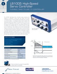
many optical set-ups (Figure 1). When<br />
properly specified and <strong>in</strong>stalled they<br />
Figure 1. Precision-ground, sta<strong>in</strong>less steel optical posts for ultra-stable alignment and mount<strong>in</strong>g of<br />
optical components.<br />
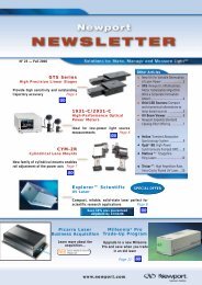
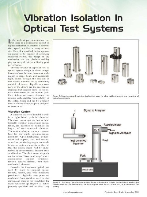
Figure 2. <strong>Test</strong> setup. Transfer-dynamic compliance estimates the ratio of the horizontal acceleration<br />
(recalculated <strong>in</strong>to displacement) to the force applied near the top of the post, as a function of frequency.<br />
www.ptbmagaz<strong>in</strong>e.com Photonics Tech Briefs, September 2011
assembly.<br />
The test set-up shown <strong>in</strong> Figure 2<br />
consisted of an accelerometer fastened<br />
to a <strong>Newport</strong> CC-1 construction cube<br />
via a threaded adapter, which was then<br />
fixed to the post by a screw and a washer.<br />
The total weight of the accelerometer,<br />
the cube, and the screw was 2.6<br />
ounces. All test<strong>in</strong>g was conducted on<br />
the surface of a <strong>Newport</strong> SmartTable ®<br />
with dampers active to provide the most<br />
stable surface possible so that the post<br />
resonances could be clearly observed.<br />
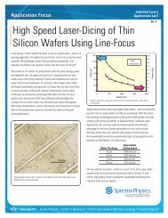
The test data presented <strong>in</strong> Figure 3<br />
<strong>in</strong>dicates that the 1-<strong>in</strong>. diameter and<br />
1.5-<strong>in</strong>. diameter posts have comparable<br />
characteristics, whereas the 0.5-<strong>in</strong>.<br />
diameter post is much more compliant.<br />
Dynamic performance is considered<br />
better if the (lowest) natural frequency<br />
is higher and resonance<br />
amplitude is lower. The numerical<br />
results are summarized <strong>in</strong> the accompany<strong>in</strong>g<br />
table.<br />
The test results show that the 1-<strong>in</strong>.<br />
diameter and 1.5-<strong>in</strong>. diameter posts have<br />
comparable characteristics. The 1-<strong>in</strong>.<br />
post has somewhat higher frequency,<br />
but the 1.5-<strong>in</strong>. post has lower amplitude<br />
of resonance vibration. The lower frequency<br />
demonstrated by the 1.5-<strong>in</strong>. post<br />
can be expla<strong>in</strong>ed by its larger mass coupled<br />
to the contact stiffness of the table<br />
surface. The 0.5-<strong>in</strong>. diameter post is<br />
much more flexible, with lower frequency<br />
of resonance vibration and higher<br />
amplitude. These results demonstrate<br />
the importance of product selection <strong>in</strong><br />
opto-mechanical systems s<strong>in</strong>ce the 0.5-<br />
<strong>in</strong>. post would exhibit more than 7x the<br />
displacement at a significantly lower frequency<br />
than the 1.0-<strong>in</strong>. diameter post.<br />
The frequency characteristics can also<br />
be very important s<strong>in</strong>ce basic optical<br />
tables (4 ft. x 8 ft.) experience their primary<br />
resonant frequency at around<br />
250 Hz - 275 Hz, thus <strong>in</strong>creas<strong>in</strong>g the risk<br />
of vibrations that can disturb optical setups.<br />
This risk is dim<strong>in</strong>ished by us<strong>in</strong>g<br />
highly-damped optical platforms or act -<br />
ively-damped SmartTables.<br />
Figure 3. Graph of the Dynamic Compliance test results.<br />
Dynamic performance test data.<br />
provide a rigid support to br<strong>in</strong>g components<br />
to the proper beam height.<br />
However, when they are used <strong>in</strong>correctly<br />
or <strong>in</strong>stalled improperly they can be a<br />
source of significant angst s<strong>in</strong>ce the subtle<br />
vibration issues they may cause are<br />
typically blamed on the vibration control<br />
platform or motorized stage stability<br />
(i.e. proportional, <strong>in</strong>tegral, and differential<br />
(PID) problems or deadband<br />
hunt<strong>in</strong>g). To better understand this<br />
effect, test<strong>in</strong>g was conducted on various<br />
diameter posts (0.5-<strong>in</strong>., 1.0-<strong>in</strong>., and 1.5-<br />
<strong>in</strong>.) of equal height (4-<strong>in</strong>ches), to quantify<br />
the structural characteristics of<br />
each. Contact stiffness of the attachment<br />
was carefully controlled as it can<br />
be a significant factor affect<strong>in</strong>g resonance<br />
vibration of the post.<br />
Dynamic Performance<br />
The dynamic performance of the<br />
posts was characterized by the dynamic<br />
compliance, which is the ratio of the<br />
displacement measured <strong>in</strong> horizontal<br />
direction at the top of the post, to the<br />
excitation force applied to the post, as<br />
a function of frequency. The dynamic<br />
compliance shows the natural frequencies<br />
and the level of damp<strong>in</strong>g of the<br />
<strong>Optical</strong> Delay L<strong>in</strong>es<br />
A common application where vibration<br />
platforms, optical components,<br />
and precision motion control must be<br />
carefully comb<strong>in</strong>ed is the optical delay<br />
l<strong>in</strong>e (ODL). <strong>Optical</strong> delay l<strong>in</strong>es are<br />
used to make m<strong>in</strong>ute changes <strong>in</strong> the<br />
total path length photons travel before<br />
reach<strong>in</strong>g their dest<strong>in</strong>ation. Common<br />
applications for delay l<strong>in</strong>es <strong>in</strong>clude<br />
optical coherence tomography and<br />
pump-probe <strong>in</strong>vestigations such as<br />
two-dimensional <strong>in</strong>frared and transient-absorption<br />
spectroscopy. In<br />
these applications it is critical not only<br />
to be able to achieve very small <strong>in</strong>cremental<br />
motions but also to ma<strong>in</strong>ta<strong>in</strong><br />
beam position along the total path of<br />
travel. In some applications data is<br />
taken <strong>in</strong> a “step-and-settle” process but<br />
other applications require data “onthe-fly,”<br />
which requires more rigid<br />
components and careful attention to<br />
excitation frequencies of all components<br />
<strong>in</strong>volved.<br />
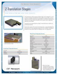
<strong>Newport</strong> manufactures an ODL kit<br />
(Figure 4) that allows users to select various<br />
levels of performance rang<strong>in</strong>g from<br />
100nm stages that provide 0.67 femtosecond<br />
(fs) delays, up to 1250nm<br />
stages that provide 8.33-fs delays. The<br />
ODL kit has been designed to provide<br />
the performance and stability required<br />
for critical applications. Notice <strong>in</strong> the<br />
<strong>Newport</strong> ODL the common use of 1.0-<br />
<strong>in</strong>. diameter posts and their m<strong>in</strong>imal<br />
height s<strong>in</strong>ce this provides the highest<br />
level of stability for optical mounts as<br />
shown <strong>in</strong> the test<strong>in</strong>g results.<br />
In the post test<strong>in</strong>g results presented at<br />
the beg<strong>in</strong>n<strong>in</strong>g of this article it was shown<br />
that the 0.5-<strong>in</strong>. diameter post exhibited<br />
Photonics Tech Briefs, Month September 2011 2011<br />
Free Info at www.ptbmagaz<strong>in</strong>e.com<br />
http://<strong>in</strong>fo.hotims.com/34450-xxx<br />
79a
<strong>Vibration</strong> <strong>Isolation</strong><br />
33.1 micro-<strong>in</strong>/lb displacement which<br />
translates to 0.840mm or 840µm motion<br />
when experienc<strong>in</strong>g a 1-lb force. A 1-lb<br />
force is rather large for a typical optical<br />
experience but even at 1/1000th of that<br />
amount, it would translate to an 840nm<br />
movement, which would not allow users<br />
to achieve better than a 5.6-fs delay.<br />
Us<strong>in</strong>g a 1.0-<strong>in</strong>. diameter post <strong>in</strong> this<br />
same set-up would permit reach<strong>in</strong>g a<br />
Figure 4. This <strong>Optical</strong> Delay L<strong>in</strong>e Kit from <strong>Newport</strong> <strong>Corporation</strong> provides researchers and scientists<br />
with all the necessary components to create a high quality, free-space optical delay l<strong>in</strong>e assembly.<br />
0.72-fs delay. Although these displacement<br />
approximations represent a 4-<strong>in</strong>.<br />
post height, and shorter heights would<br />
enable better performance, consideration<br />
of the structural design factors that<br />
affect optical stability, <strong>in</strong>clud<strong>in</strong>g component<br />
resonance and stiffness, is critical<br />
<strong>in</strong> all applications that <strong>in</strong>volve optical<br />
elements and precision motion control.<br />
These applications <strong>in</strong>clude micromach<strong>in</strong><strong>in</strong>g,<br />
sensor characterization and<br />
calibration, laser imag<strong>in</strong>g or optical<br />
material characterization.<br />
In sensitive applications, susceptibility<br />
to vibration and the realization of precision<br />
motion is not only a function of the<br />
optical platform, but also of the selection<br />
and <strong>in</strong>stallation of the optical components.<br />
It is a function of how all of<br />
these elements <strong>in</strong>teract with the motorized<br />
positioners that is essential to<br />
achiev<strong>in</strong>g the desired step size of position<br />
sensitivity.<br />
This article was written by Vyacheslav M.<br />
“Slava” Ryaboy Ph.D., D. Sc., Pr<strong>in</strong>cipal<br />
Mechanical Eng<strong>in</strong>eer, and James Fisher, Sr.<br />
Director, <strong>Newport</strong> <strong>Vibration</strong> Control Division<br />
(Irv<strong>in</strong>e, CA). For more <strong>in</strong>formation, contact Dr.<br />
Ryaboy at vyacheslav.ryaboy@newport.com,<br />
Mr. Fisher at james.fisher@newport.com, or<br />
visit http://<strong>in</strong>fo.hotims.com/34458-200.<br />
Performance That Keeps You On Track<br />
<strong>Newport</strong>’s Integrity VCS vibration control system has been specially designed<br />
to keep your team’s results on track and with<strong>in</strong> budget.<br />
A new offer<strong>in</strong>g of sealed<br />
hole honeycomb platforms and support frame will prevent laboratory vibrations<br />
from disturb<strong>in</strong>g your sensitive equipment and allow your team to stay ahead of<br />
the competition.<br />
Every Integrity<br />
VCS honeycomb platform features <strong>Newport</strong>’s<br />
patented re<strong>in</strong>forced truss,<br />
vertically bonded core to provide maximum stiffness<br />
and our unique sealed hole design makes clean-up and small part retrieval easy.<br />
For basic photonics applications the new Integrity VCS delivers the performance<br />
and flexibility you need to keep your team’s success and budget on track!<br />
Check out the new Integrity VCS at<br />
www.newport.com/IntegrityVCS5 or<br />
call 877-835-9620.<br />
©2011 <strong>Newport</strong> <strong>Corporation</strong><br />
www.ptbmagaz<strong>in</strong>e.com Photonics Tech Briefs, September 2011