Model LIWDDSR20...twin screw loss-in-weight feeder
Model LIWDDSR20...twin screw loss-in-weight feeder
Model LIWDDSR20...twin screw loss-in-weight feeder

You also want an ePaper? Increase the reach of your titles
YUMPU automatically turns print PDFs into web optimized ePapers that Google loves.
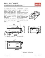
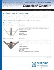
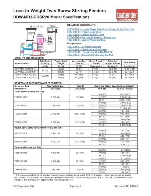
Loss-In-Weight Tw<strong>in</strong> Screw Stirr<strong>in</strong>g Feeders<br />
DDW-MD3-DDSR20 <strong>Model</strong> Specifications<br />
Screw<br />
and<br />
Tube<br />
Extension<br />
Hopper<br />
Manual Refill Lid<br />
Feeder<br />
Congrav ®<br />
Controls<br />
AC Motor<br />
Control<br />
Monoblock Scale with<br />
S<strong>in</strong>gle DigiMASS-2<br />
Load Cell<br />
RELATED DOCUMENTS:<br />
3210-C00-1 – Loss-In-Weight Tw<strong>in</strong> Screw Stirr<strong>in</strong>g Table of Contents<br />
3210-C25-1 – Product Description<br />
3210-C26-1 – <strong>Model</strong> Selection Guide<br />
3210-C31-1 – Standard Options and Accessories<br />
7200-C25-1 – Loss-In-Weight Controls<br />
Components:<br />
1300-C21-3 – AC Motor Controller<br />
1300-C21-9 – Digital and Analog Scales<br />
1300-C21-10 – Digital Load Cell (DigiMASS-2)<br />
7200-C30-5 – ISC Controls (ISC-CM, ISC-FC)<br />
WEIGHTS AND MEASURES<br />
Total Scale Feeder Dead Max. Ingredient Screw Trough Extension<br />
Total Volume<br />
<strong>Model</strong> Number<br />
Capacity Weight<br />
Capacity Volume Hopper Volume<br />
Kg (lb) Kg (lb) Kg (lb) liters (cu.ft.) liters (cu.ft.) liters (cu.ft.)<br />
DDW-MD3-DDSR20-10<br />
19 (42) 26 (57) 2.75 (0.1) 10 (0.35) 12.75 (0.45)<br />
45 (99)<br />
DDW-MD3-DDSR20-20 23 (51) 22 (49) 2.75 (0.1) 20 (0.71) 22.75 (0.8)<br />
DDW-H31-DDSR20-30R<br />
31 (66) 59 (130) 2.75 (0.1) 30 (1.1) 32.75 (1.2)<br />
90 (198)<br />
DDW-H31-DDSR20-50R 35 (77) 55 (121) 2.75 (0.1) 50 (1.8) 52.75 (1.9)<br />
SCREW AND TUBE SIZES AND FEED RATES<br />
Screw and Tube<br />
Designation<br />
Max. Particle Size Tube ID Max. Feed Rate at Specified Screw Speed*<br />
mm (<strong>in</strong>ch) mm (<strong>in</strong>ch) RPM (Hz) cu.ft./hr (liters/hr)<br />
Tw<strong>in</strong> Concave Screws and Tube<br />
380 (75) 0.22 (6.22)<br />
TC20/05-190T 0.2 (0.01) 19 (0.75)<br />
192 (75) 0.111 (3.14)<br />
66 (75) 0.0381 (1.08)<br />
380 (75) 0.994 (28.2)<br />
TC20/12-200T 0.3 (0.01) 20 (0.79)<br />
192 (75) 0.502 (14.2)<br />
66 (75) 0.173 (4.89)<br />
380 (75) 1.84 (52.2)<br />
TC20/11-223T 0.7 (0.03) 22.3 (0.88)<br />
192 (75) 0.93 (26.3)<br />
66 (75) 0.32 (9.06)<br />
380 (75) 3.68 (104)<br />
TC20/20-223T 0.7 (0.03) 22.3 (0.88)<br />
192 (75) 1.86 (52.7)<br />
66 (75) 0.639 (18.1)<br />
Double Spiral Screws (Non-Intermesh<strong>in</strong>g) and Tube<br />
380 (75) 1.61 (45.6)<br />
SS13/10-200T 3.5 (0.14) 20 (0.79)<br />
192 (75) 0.814 (23)<br />
66 (75) 0.28 (7.92)<br />
380 (75) 2.65 (75.1)<br />
SS13/15-223T 4.7 (0.18) 22.3 (0.88)<br />
192 (75) 1.34 (37.9)<br />
66 (75) 0.46 (13)<br />
Tw<strong>in</strong> Spiral Screws and Tube<br />
380 (75) 3.74 (106)<br />
TS18/13-200T 1.0 (0.04) 20 (0.79)<br />
192 (75) 1.89 (53.4)<br />
66 (75) 0.649 (18.4)<br />
380 (75) 6.12 (173)<br />
TS18/19-200T 1.0 (0.04) 20 (0.79)<br />
192 (75) 3.09 (87.5)<br />
66 (75) 1.06 (30.1)<br />
380 (75) 10 (284)<br />
TS18/29-200T 1.0 (0.04) 20 (0.79)<br />
192 (75) 5.07 (144)<br />
66 (75) 1.74 (49.3)<br />
* The <strong>screw</strong> speed shown is the standard maximum Loss-In-Weight <strong>screw</strong> speed (75% of full speed). Higher maximum <strong>screw</strong> speeds<br />
are possible. The Maximum Feed Rates are theoretical values based on a <strong>screw</strong> fill<strong>in</strong>g efficiency of 100% at the specified <strong>screw</strong> speed.<br />
Ingredient flow characteristics determ<strong>in</strong>e the <strong>screw</strong> fill<strong>in</strong>g efficiency.<br />
3/05 Supersedes 8/04 Page 1 of 6 Document: 3210-C30-2
DDW-MD3-DDSR20 <strong>Model</strong> Specifications<br />
MATERIALS OF CONSTRUCTION<br />
Scale<br />
Mild Steel baseplate, enamel pa<strong>in</strong>ted, Alum<strong>in</strong>um, mill f<strong>in</strong>ish and 304SS<br />
Unweighed Process Connection 304SS, electropolished, with polyurethane flexible connection to Vertical Outlet<br />
Screw Trough<br />
304SS, 2B f<strong>in</strong>ish <strong>in</strong>side, mirror f<strong>in</strong>ish outside<br />
Screw, Tube and Agitator 304SS, 2B f<strong>in</strong>ish, electropolished<br />
Screw and Agitator Drive Shafts 304SS<br />
Drive Shaft Seals<br />
Screws and Screw Trough Agitator: Lip Seals <strong>in</strong> gearbox;<br />
Extension Hopper Agitator (-xxR): Viton or BunaN<br />
Extension Hopper and Lid 304SS, 2B f<strong>in</strong>ish <strong>in</strong>side, mirror f<strong>in</strong>ish outside<br />
Gaskets<br />
Neoprene<br />
MECHANICAL PROCESS CONNECTIONS<br />
Refill (on Lid) Pipe stub connection. See Mechanical Draw<strong>in</strong>g for location and size.<br />
Pipe stub connection. See Mechanical Draw<strong>in</strong>g for location and size. The vent allows dusty air to escape dur<strong>in</strong>g refill<br />
Vent (on Lid) and atmospheric air to enter dur<strong>in</strong>g feed<strong>in</strong>g. Brabender offers a vent filter for pellets or non-dusty <strong>in</strong>gredients. For<br />
powders, dust collector is by others.<br />
Outlet<br />
Standard is vertical outlet with Unweighed Process Connection.<br />
ENVIRONMENTAL SPECIFICATIONS<br />
Temperature<br />
Ambient Operat<strong>in</strong>g: 0° to 40°C (32° to 104°F), Storage: -40° to 40°C (-40° to 104°F)<br />
Ingredient Cont<strong>in</strong>uous: 0° to 80°C (32° to 176°F), Intermittent: -20° to 90°C (-4° to 194°F)<br />
Humidity<br />
Ambient 5% to 95% (no condensation)<br />
Ingredient The <strong>in</strong>gredient flow characteristics may vary with excessive humidity. The <strong>feeder</strong> must be dry when feed<strong>in</strong>g.<br />
Pressure<br />
Altitude To 10,000 feet (3,048 m)<br />
Ingredient The pressure <strong>in</strong>side the <strong>feeder</strong> should be the same as outside the <strong>feeder</strong> (see Option FC-4 below).<br />
Vibration<br />
The load cell has adjustable filter levels for most typical <strong>in</strong>-plant vibration.<br />
CONTINUOUS FEED RATE ACCURACY (Batch<strong>in</strong>g Accuracy: ± 1 /10,000 Scale Capacity)<br />
Measur<strong>in</strong>g Criteria 30 consecutive samples over sample time of 10 to 120 seconds<br />
Feed Range<br />
15:1 <strong>screw</strong> speed range<br />
Repeatability<br />
± 0.2% to 1% of sample average at 2 sigma, depend<strong>in</strong>g on <strong>in</strong>gredient flow properties<br />
L<strong>in</strong>earity<br />
± 0.5% over a <strong>screw</strong> speed range of 10:1 for each <strong>screw</strong> type<br />
Standard Options and Accessories (See Document 3210-C31-1 for Details)<br />
Scale Options<br />
SC-1(A/B/C) Stra<strong>in</strong> Gauge Load Cell<br />
Extension Hoppers and Lids<br />
XH-2(A/B) Extension Hopper Lid<br />
XH-4B<br />
Extension Hopper Safety<br />
Grate<br />
XH-5A Extension Hopper Relief Cone<br />
XH-7<br />
Bag Load<strong>in</strong>g Hopper with<br />
Safety Grate and Lid<br />
XH-8 Extension Hopper Handles<br />
Screw Trough and Agitator Options<br />
TA-3 Double Agitator Blades<br />
Screw and Tube Options<br />
ST-2C Outboard Screw Bear<strong>in</strong>g<br />
ST-5 Air Purged Seal<br />
Optional Materials of Construction<br />
MC-1(A/B/D) Scale F<strong>in</strong>ish Options<br />
MC-3(A-D)<br />
316SS Ingredient Contact<br />
Parts<br />
MC-4(A-D) Food Grade Construction<br />
Motor and Drive Options<br />
MD-2(A-L) Screw VFD Options<br />
MD-5(A-L)<br />
Extension Hopper Agitator<br />
VFD Options<br />
Flexible Connections<br />
FC-1 Flexible Inlet Connection<br />
FC-2 Flexible Vent Connection<br />
FC-3 Flexible Outlet Connection<br />
FC-4 Outlet Pressure Compensation<br />
Refill Options<br />
RF-1 Refill Knife Gate (NEMA 4)<br />
RF-2 Refill Knife Gate Limit Switches<br />
RF-3 Mount<strong>in</strong>g Flanges for Knife Gate<br />
Modifications for Hazardous Areas<br />
XP-2 Refill Knife Gate (NEMA 7)<br />
XP-3<br />
Refill Knife Gate Limit<br />
Switches (CL.I, DIV.1)<br />
XP-5(A-D)<br />
Loss-In-Weight Feeder<br />
Suitable for Hazardous Areas<br />
Accessories<br />
ACC-1A Vibrator on Extension Hopper<br />
ACC-3 Level Probe Connection<br />
ACC-7A Vent Dust Bag<br />
ACC-16A Feeder Lift Station<br />
Extra Parts Ordered with Feeder<br />
EP-2 Extra Screw<br />
EP-3 Extra Tube<br />
EP-4 Extra Screw Trough Agitator<br />
EP-5 Extra Extension Hopper Agitator<br />
3/05 Supersedes 8/04 Page 2 of 6 Document: 3210-C30-2
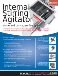
Mechanical Draw<strong>in</strong>g<br />
DDW-MD3-DDSR20 <strong>Model</strong> Specifications<br />
ITEM DESCRIPTION<br />
1 DDW-MD3-DDSR20 Feeder<br />
2 Screw Trough Agitator<br />
3 Extension Hopper - 20L (0.71 cu.ft.)<br />
5 Screw<br />
6 Tube<br />
7 Auto Refill Lid<br />
8 Inlet (On Auto Refill Lid)<br />
9 Manual Refill Lid (Optional)<br />
10 Vent Dust Cartridge (Optional)<br />
11 Unweighed Process Connection<br />
12 Monoblock Scale with S<strong>in</strong>gle DigiMASS-2 Load Cell<br />
(MD3)<br />
13 NEMA 4 Junction Boxes (2)<br />
<br />
<br />
<br />
Notes:<br />
1) All Dimensions are <strong>in</strong> Millimeters [Inches]<br />
2) The Junction Boxes shown are for use with Congrav ® S and<br />
Congrav ® L/M3 controllers - other Junction Boxes are similar.<br />
Description ‘A’ ‘C’ ‘D’<br />
Standard Tube Length 100 [3.9] 112 [4.4] 234 [9.2]<br />
Description<br />
‘E’<br />
Standard Inlet Diameter 100 [3.9]<br />
Empty Feeder and Scale Weight<br />
Kg (lb)<br />
With 10L (0.35 cu.ft.) Extension Hopper 31 (68)<br />
With 20L (0.71 cu.ft.) Extension Hopper 35 (77)<br />
With 30L (1.1 cu.ft.) Extension Hopper (R) 76 (167)<br />
With 50L (1.8 cu.ft.) Extension Hopper (R) 80 (176)<br />
Screw Availability<br />
1) All Tubes and standard Concave Screws are available <strong>in</strong> Standard<br />
lengths from stock<br />
2) Whenever possible, use a stocked length <strong>screw</strong> and tube and<br />
move the <strong>in</strong>let location to align the <strong>in</strong>let and outlet of the <strong>feeder</strong><br />
with the exist<strong>in</strong>g equipment<br />
3/05 Supersedes 8/04 Page 3 of 6 Document: 3210-C30-2
DDW-MD3-DDSR20 <strong>Model</strong> Specifications<br />
Typical Feeder Electrical Connections – ISC Controls / OP1 Display - S<strong>in</strong>gle Feeder<br />
Note: Wir<strong>in</strong>g to agitator motors is not shown. The Extension Hopper Agitator Motor (where applicable) requires either a VFD<br />
(variable speed) to be specified or a motor starter (fixed speed) to be provided (by others).<br />
Feeder ‘On’<br />
Output<br />
Refill<br />
Output<br />
Feeder Interlock<br />
Input<br />
}<br />
}<br />
}<br />
Congrav ® OP 1<br />
TECHNOLOGIE<br />
230VAC<br />
AC Power<br />
10A Fuses<br />
Communication ‘Out’<br />
(RS-485)<br />
S1 Setpo<strong>in</strong>t 90.549 kg/h<br />
Act.value 90.550 kg/h<br />
ISC-FC<br />
(Mounted on Feeder)<br />
(AC Motor wired at<br />
factory - max.1⁄2 HP)<br />
ISC-CM<br />
(Mounted on Feeder)<br />
(Load Cell wired<br />
at factory)<br />
Interconnect<strong>in</strong>g Cable<br />
(Wired at factory)<br />
(AC Power Wir<strong>in</strong>g, Communication Wir<strong>in</strong>g and<br />
Fuses are not <strong>in</strong>cluded with the <strong>feeder</strong>)<br />
Typical Feeder Electrical Connections – ISC Controls / RC4 Display - Multiple Feeders<br />
Note: Wir<strong>in</strong>g to agitator motors is not shown. The Extension Hopper Agitator Motor (where applicable) requires either a VFD<br />
(variable speed) to be specified or a motor starter (fixed speed) to be provided (by others).<br />
Feeder ‘On’<br />
Output<br />
Refill<br />
Output<br />
Feeder Interlock<br />
Input<br />
Congrav ® RC 4<br />
}<br />
}<br />
}<br />
1 2 3 4 5 6 7 8 9 10 11 12 13 14 15 16<br />
TECHNOLOGIE<br />
230VAC<br />
AC Power<br />
10A Fuses<br />
Communication ‘Out’<br />
(RS-485)<br />
ISC-FC<br />
(Mounted on Feeder)<br />
(AC Motor wired at<br />
factory - max.1⁄2 HP)<br />
ISC-CM<br />
(Mounted on Feeder)<br />
(Load Cell wired<br />
at factory)<br />
Communication ‘In’ (RS-485)<br />
} (From Next Feeder)<br />
Interconnect<strong>in</strong>g Cable<br />
(Wired at factory)<br />
(AC Power Wir<strong>in</strong>g, Communication Wir<strong>in</strong>g and<br />
Fuses are not <strong>in</strong>cluded with the <strong>feeder</strong>)<br />
FEEDER ELECTRICAL SPECIFICATIONS - FEEDERS WITH ISC CONTROLS<br />
(See Document 7200-C30-5 for Information on ISC Controls)<br />
Screw/Screw Trough Agitator AC<br />
Motor Controller – ISC-FC<br />
Feeder Controller – ISC-CM<br />
Screw/Screw Trough Agitator<br />
Motor<br />
Extension Hopper Agitator Motor<br />
Load Cell<br />
Input Power: 230 VAC, 50/60Hz, S<strong>in</strong>gle Phase;<br />
Motor Output: 230 VAC, 3 Phase;<br />
Motor Control I/O: RS-485 (ISC-CM); 24 VDC Out, 2 Dry Contact Outputs;<br />
Enclosure: IP55 (NEMA 12)<br />
Input Power: 24 VDC (from ISC-FC);<br />
Load Cell Input: RS-422 (DigiMASS-2);<br />
Motor Control Output: RS-485 (ISC-FC); Congrav ® Communications (ISC);<br />
Enclosure: IP65 (NEMA 12)<br />
1⁄2 HP (0.37 KW), 230/460 VAC, 3 Phase, TEFC<br />
1⁄4 HP (0.18 KW), 230/460 VAC, 3 Phase, TEFC; 6 RPM gearbox output at 60 Hz<br />
Monoblock Scale with a S<strong>in</strong>gle DigiMASS-2 Load Cell with Serial Communications (RS-422);<br />
Enclosure: IP64 (NEMA 12)<br />
3/05 Supersedes 8/04 Page 4 of 6 Document: 3210-C30-2
DDW-MD3-DDSR20 <strong>Model</strong> Specifications<br />
Typical Feeder Electrical Connections – Congrav® S Controls - S<strong>in</strong>gle Feeder<br />
Note: Wir<strong>in</strong>g to agitator motors is not shown. The Extension Hopper Agitator Motor (where applicable) requires either a VFD<br />
(variable speed) to be specified or a motor starter (fixed speed) to be provided (by others).<br />
JB-1<br />
Load Cell Junction Box<br />
for DigiMASS-2<br />
(Mounted on Feeder)<br />
JB-2<br />
Motor Junction Box<br />
with Term<strong>in</strong>als<br />
(Mounted on Feeder)<br />
115V, 1Ph<br />
AC Power<br />
15A Fuse<br />
Load Cell Communications (RS-422)<br />
AC Motor Controller (VFD)<br />
Allen-Bradley PowerFlex 40<br />
<strong>Model</strong> 22B-V2P3N104<br />
115V, S<strong>in</strong>gle Phase In<br />
230V, 3 Phase Out (0.5 HP)<br />
(Provides Class 10<br />
overload protection)<br />
Field<br />
Wir<strong>in</strong>g<br />
Module<br />
Congrav ®<br />
S<br />
TECHNOLOGIE<br />
S1 Setpo<strong>in</strong>t 90.549 kg/h<br />
Act.value 90.550 kg/h<br />
(Congrav ® S, Field Wir<strong>in</strong>g Module, I/O Cable Set,<br />
AC Power Wir<strong>in</strong>g, Wir<strong>in</strong>g to JB-1 and JB-2, and<br />
Fuses are not <strong>in</strong>cluded with the <strong>feeder</strong>)<br />
Typical Feeder Electrical Connections – Congrav® L/M3A Controls - Multiple Feeders<br />
Note: Wir<strong>in</strong>g to agitator motors is not shown. The Extension Hopper Agitator Motor (where applicable) requires either a VFD<br />
(variable speed) to be specified or a motor starter (fixed speed) to be provided (by others).<br />
JB-1<br />
Load Cell Junction Box<br />
for DigiMASS-2<br />
(Mounted on Feeder)<br />
JB-2<br />
Motor Junction Box<br />
with Term<strong>in</strong>als<br />
(Mounted on Feeder)<br />
Load Cell Communications (RS-422)<br />
AC Motor Controller (VFD)<br />
Lenze 8200 Vector<br />
<strong>Model</strong> E82EV371_2B<br />
230V, S<strong>in</strong>gle Phase In<br />
230V, 3 Phase Out (0.5 HP)<br />
Digital<br />
Field<br />
Wir<strong>in</strong>g<br />
Module<br />
Congrav ® L/M 3<br />
1 2 3 4 5 6 7 8 9 10 11 12 13 14 15 16<br />
TECHNOLOGIE<br />
230V, 1Ph<br />
AC Power<br />
10A Fuse<br />
(Congrav ® L/M3A, Field Wir<strong>in</strong>g Modules, I/O Cable Set,<br />
AC Power Wir<strong>in</strong>g, Wir<strong>in</strong>g to JB-1 and JB-2, and<br />
Fuses are not <strong>in</strong>cluded with the <strong>feeder</strong>)<br />
FEEDER ELECTRICAL SPECIFICATIONS - FEEDERS WITH CONGRAV ® CONTROLS<br />
(See Document 7200-C00-1 for Information on Congrav ® Controls)<br />
Input Power: 115 VAC, 50/60Hz, S<strong>in</strong>gle Phase;<br />
Screw/Screw Trough Agitator<br />
Motor Output: 230 VAC, 3 Phase;<br />
AC Motor Controller (A-B VFD)<br />
Motor Control Input: 0-10V;<br />
– Congrav ® S<br />
Enclosure: NEMA 1 with Keypad for Speed Control and Run/Stop<br />
Screw/Screw Trough Agitator<br />
AC Motor Controller (Lenze VFD)<br />
– Congrav ® L/M3A<br />
Screw/Screw Trough Agitator<br />
Motor<br />
Extension Hopper Agitator Motor<br />
Load Cell for Congrav ® Controls<br />
Feeder Mounted Junction Boxes<br />
for use with Congrav ® Controls<br />
Input Power: 230 VAC, 50/60Hz, S<strong>in</strong>gle Phase;<br />
Motor Output: 230 VAC, 3 Phase;<br />
Motor Control Input: RS-485;<br />
Enclosure: NEMA 1 with Keypad for Speed Control and Run/Stop<br />
1⁄2 HP (0.37 KW), 230/460 VAC, 3 Phase, TEFC<br />
1⁄4 HP (0.18 KW), 230/460 VAC, 3 Phase, TEFC; 6 RPM gearbox output at 60 Hz<br />
Monoblock Scale with a S<strong>in</strong>gle DigiMASS-2 Load Cell with Serial Communications (RS-422);<br />
Enclosure: IP64 (NEMA 12)<br />
1 NEMA 4 Junction Box for Motor Connections; 1 NEMA 4 Junction Box for DigiMASS-2 Load Cell<br />
Connections<br />
3/05 Supersedes 8/04 Page 5 of 6 Document: 3210-C30-2
DDW-MD3-DDSR20 <strong>Model</strong> Specifications<br />
Mount<strong>in</strong>g Dimensions for AC Motor Controllers<br />
Allen-Bradley VFD (Congrav ® S or User-Supplied Controls)<br />
100 (3.94)<br />
87 (3.43)<br />
180<br />
(7.09)<br />
168<br />
(6.61)<br />
With IP30/NEMA 1 Cover Option<br />
136 (5.35)<br />
87.4<br />
(3.44)<br />
79.1 (3.11)<br />
64.1 (2.52)<br />
40.6 (1.60)<br />
25.6 (1.01)<br />
Æ 22.2<br />
(0.87)<br />
Lenze VFD (Congrav ® L/M3A Controls)<br />
27.5 (1.1) Dimensions are <strong>in</strong> millimeters (<strong>in</strong>ches)<br />
6.5 (0.26)<br />
120 (4.7)<br />
150 (5.9)<br />
170 (6.7)<br />
109.9<br />
(4.33)<br />
5.5 (0.22) 33.0<br />
(1.30)<br />
Dimensions are <strong>in</strong> millimeters (<strong>in</strong>ches)<br />
74.3<br />
(2.93)<br />
Shipp<strong>in</strong>g Weight: 2 Kg (4.9 lbs)<br />
E82EV371<br />
30 (1.2)<br />
60 (2.4)<br />
140 (5.5)<br />
Shipp<strong>in</strong>g Weight: 0.85 Kg (1.9 lbs)<br />
Typical Feeder Electrical Connections with Other Controls<br />
Note: Wir<strong>in</strong>g to agitator motors is not shown. The Extension Hopper Agitator Motor (where applicable) requires either a<br />
VFD (variable speed) to be specified or a motor starter (fixed speed) to be provided (by others).<br />
Stra<strong>in</strong> Gauge Load Cell with<br />
Precision Amplifier<br />
JB-1<br />
Stra<strong>in</strong> Gauge Load Cell<br />
Junction Box with<br />
Analog to Digital<br />
Pre-Amplifier (AED)<br />
(Mounted on Feeder)<br />
}<br />
Load Cell Communications<br />
(RS-422)<br />
10-30VDC<br />
DC Power<br />
Stra<strong>in</strong> Gauge Load Cell with Analog<br />
Amplifier<br />
JB-1<br />
Stra<strong>in</strong> Gauge Load Cell<br />
Junction Box with Analog<br />
Pre-Amplifier (BT-0296)<br />
(Mounted on Feeder)<br />
}<br />
Load Cell Signal<br />
(0-10V, 0-20ma, or 4-20ma)<br />
120VAC<br />
AC Power<br />
Stra<strong>in</strong> Gauge Load Cell with No<br />
Amplifier<br />
JB-1<br />
Stra<strong>in</strong> Gauge Load Cell<br />
Junction Box with<br />
Term<strong>in</strong>als<br />
(Mounted on Feeder)<br />
}<br />
To Load Cell Amplifier<br />
JB-2<br />
Motor Junction Box<br />
with Term<strong>in</strong>als<br />
(Mounted on Feeder)<br />
}<br />
To AC Motor Controller (VFD)<br />
JB-2<br />
Motor Junction Box<br />
with Term<strong>in</strong>als<br />
(Mounted on Feeder)<br />
}<br />
To AC Motor Controller (VFD)<br />
JB-2<br />
Motor Junction Box<br />
with Term<strong>in</strong>als<br />
(Mounted on Feeder)<br />
}<br />
To AC Motor Controller (VFD)<br />
Note: The Disconnect, Fuse Holders, Fuses and wir<strong>in</strong>g to the <strong>feeder</strong> are by others.<br />
FEEDER ELECTRICAL SPECIFICATIONS - FEEDERS WITH USER-SUPPLIED CONTROLS<br />
Input Power: 115 VAC, 50/60Hz, S<strong>in</strong>gle Phase;<br />
Screw/Screw Trough Agitator AC Motor Output: 230 VAC, 3 Phase;<br />
Motor Controller (A-B VFD) Motor Control Input: 0-10V or 4-20ma;<br />
Enclosure: NEMA 1 with Keypad for Speed Control and Run/Stop<br />
Screw/Screw Trough Agitator<br />
1⁄2 HP (0.37 KW), 230/460 VAC, 3 Phase, TEFC<br />
Motor<br />
Extension Hopper Agitator Motor 1⁄4 HP (0.18 KW), 230/460 VAC, 3 Phase, TEFC; 6 RPM gearbox output at 60 Hz<br />
Monoblock Scale with a S<strong>in</strong>gle Analog Stra<strong>in</strong> Gauge Load Cell;<br />
Load Cell for User Controls Enclosure: IP67 (NEMA 4);<br />
Amplifier / Signal Type must be specified<br />
Feeder Mounted Junction Boxes<br />
for use with User-Supplied<br />
Controls<br />
1 NEMA 4 Junction Box for Motor Connections; 1 NEMA 4 Junction Box for Analog Load Cell<br />
Connections<br />
Head Office:<br />
6500 Kestrel Road<br />
Mississauga, Ontario<br />
Canada, L5T 1Z6<br />
Telephone:<br />
Toll Free:<br />
Facsimile:<br />
Email:<br />
(905) 670-2933<br />
(888) 284-4574<br />
(905) 670-2557<br />
sales@brabenderti.com<br />
3/05 Supersedes 8/04 Page 6 of 6 Document: 3210-C30-2