Congrav S...single feeder controller - Sawyer/Hanson Innovations
Congrav S...single feeder controller - Sawyer/Hanson Innovations
Congrav S...single feeder controller - Sawyer/Hanson Innovations

You also want an ePaper? Increase the reach of your titles
YUMPU automatically turns print PDFs into web optimized ePapers that Google loves.
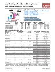
Continuous Gravimetric Feeder Controls<br />
<strong>Congrav</strong> ® S Model Specifications<br />
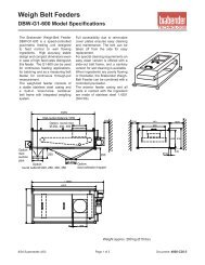
Weigh Belt Feeder<br />
Loss-In-Weight Feeder<br />
VFD<br />
VFD<br />
<strong>Congrav</strong> ® S Controls<br />
Xs<br />
<strong>Congrav</strong> ® S Controls<br />
Xs<br />
<strong>Congrav</strong> S<br />
Step<br />
<strong>Congrav</strong> S<br />
Step<br />
H<br />
G<br />
8<br />
8<br />
9<br />
6<br />
9<br />
6<br />
Optional<br />
Host<br />
Optional<br />
Host<br />
RELATED DOCUMENTS:<br />
7200-C00-1 – Continuous Gravimetric Controls Table of Contents<br />
7200-C25-1 – Product Description<br />
7200-C26-1 – Model Selection Guide<br />
7200-C31-1 – Standard Options and Accessories<br />
MODELS<br />
Model Number<br />
<strong>Congrav</strong>-S/H<br />
Software<br />
Type<br />
H<br />
Single Feeder Control<br />
Feeder Types<br />
Loss-In-Weight Screw Feeders<br />
Loss-In-Weight Vibrating Feeders<br />
Loss-In-Weight Fiber Feeders<br />
Loss-In-Weight Liquid Feeders<br />
<strong>Congrav</strong>-S/G G Weigh Belt Feeders<br />
Sealed Faceplate<br />
Quick Access Keys<br />
For Fast Access to Data and<br />
Common Functions<br />
Start Key with Feeder Status<br />
Tri-Color LED<br />
LED Shows:<br />
Feeder Running<br />
Feeder Fault<br />
Feeder Interlocked<br />
2 Line by 24 Character Dot Matrix<br />
Display with Backlighting<br />
Display Shows:<br />
Feeder Status<br />
Feeder Configuration Data<br />
Setpoint (Kg/hr, lb/hr, or %)<br />
Actual (Kg/hr, lb/hr)<br />
Weight (Kg, lb)<br />
Total Throughput (Kg, lb)<br />
Motor Speed (%)<br />
Deviation from Setpoint (%)<br />
Load Cell Filter Reading (%)<br />
Stop and Reset Alarm Keys<br />
Industrial Duty Keypad<br />
SOFTWARE<br />
Software Configuration<br />
Typical Configuration Data<br />
Feeding Modes<br />
Alarms<br />
Alarm Modes<br />
Manual Data Entry or Automatic Self-Tuning<br />
Maximum Output, PID, Bulk Density<br />
Gravimetric Feeding Normal Gravimetric Mode with Refill<br />
Volumetric Feeding Only for Loss-In-Weight - Run at a constant motor speed with Refill<br />
Only for Loss-In-Weight Feeders - Gravimetric Mode to nearly<br />
Gravimetric Discharging<br />
empty the hopper - no Refill<br />
Run at a constant motor speed to nearly empty the hopper - no<br />
Discharging<br />
Refill<br />
Underload/Overload; Speed Min/Max; Deviation +/-; Refill Fault; Load Cell Fault<br />
Warning Only On Alarm, Cut-Out On Alarm with configurable Time Delay<br />
ELECTRICAL SPECIFICATIONS<br />
85-250 VAC, 47-63 Hz, Single Phase, 35VA; Standard IEC 3 prong connector (with two 2A, Time<br />
Input Power<br />
Delay fuses)<br />
Enclosure Rating<br />
Electrical Approvals<br />
Electrical Standards<br />
Front Panel: IP65; Rear Housing IP30<br />
IEC, CE<br />
VDE 0842 Part 4, IEC 801 Part 4 (Burst); VDE 0842 Part 2, IEC 801 Part 2 (ESD), VDE 0878/<br />
VDE 0875 (Radio Interference), EN60204-1:1992, EN50081:1993, EN50082:1994<br />
8/04 Supersedes 4/03 Page 1 of 4 Document: 7200-C30-1
Continuous Gravimetric <strong>Congrav</strong> ® S Model Specifications<br />
BASE UNIT INPUTS, OUTPUTS AND COMMUNICATIONS<br />
All I/O wiring to the separate Field Wiring Module with Screw Terminals. The Field Wiring Module is<br />
I/O Connections<br />
connected by cables to the <strong>Congrav</strong> ® S (not included if <strong>controller</strong> is ordered without a panel).<br />
Feeder I/O<br />
Load Cell<br />
Motor<br />
User I/O<br />
8 Digital Inputs<br />
8 Digital Outputs<br />
IDL-F or DigiMASS®-2 Digital Load Cell or AED<br />
Precision Strain Gauge Load Cell Amplifier<br />
Standard Strain Gauge Load Cell<br />
Motor Speed Control Signal<br />
Motor Speed Feedback<br />
Interlock<br />
Start; Stop; Alarm Reset; Refill (H), Autotare (G);<br />
Gravimetric Discharge (H)<br />
Key Switch<br />
Digital, RS-422<br />
Analog, 0-25mV (Optional 0-10V)<br />
Analog, 0-10V, 0.5s per Update<br />
Digital Tachometer, Pulse – Max. 6KHz<br />
Analog, 0-10V<br />
Isolated, Selectable Logic, 24V<br />
Isolated, Positive Logic, 24V, Pulse (0.5-2sec)<br />
Isolated, Positive Logic, 24V<br />
Operation; Alarm; Refill (H), Autotare (G) Dry Contact, SPDT (230VDC, 2A)<br />
Feed Rate Deviation; Overload; Underload; Alarm<br />
Report<br />
Throughput Pulse (Min. Duration: 100ms, Maximum<br />
Frequency: 5Hz)<br />
1 Analog Input Remote Setpoint *1 Isolated, 0-10V<br />
1 Analog Output Actual Feed Rate Isolated, 0/4-20ma<br />
System Communications<br />
Host<br />
Communications<br />
With other <strong>Congrav</strong> ® S controls<br />
Isolated, Positive Logic, Open Emitter, 24V,<br />
0.25A<br />
Isolated, Negative Logic, Open Collector, 24V,<br />
0.25A<br />
RS-422 Master/Slave operation<br />
Standard Host Communications RS-422 (Siemens RK512 with 3964R)<br />
Optional Internal Add-in Card<br />
Profibus-DP<br />
Optional External DataLink Module<br />
Data Highway+, Modbus RTU or DF1<br />
*1 The Analog Input is only available if not used for Motor Speed Feedback<br />
ENVIRONMENTAL SPECIFICATIONS<br />
Temperature Ambient Operating: 0° to 45°C (32° to 112°F), Storage: -40° to 85°C (-40° to 185°F)<br />
Humidity Ambient 0% to 85% (no condensation)<br />
Pressure Altitude To 10,000 feet (3,048 m)<br />
Vibration<br />
Normal plant vibration does not effect performance.<br />
ACCURACY<br />
Digital Load Cell 1:1,000,000 resolution (IDL-F, AED); 1:4,000,000 resolution (DigiMASS ® )<br />
Analog Load Cell<br />
1:32,000 resolution<br />
Standard Options and Accessories (See Document 7200-C31-1 for Details)<br />
I/O Options<br />
IO-3A<br />
Analog I/O Card (2 AI, 2 AO)<br />
with 6’ Cable<br />
IO-5A Printer Interface<br />
IO-9 Field Wiring Module<br />
IO-10 Field Wiring Cable Set<br />
Host Communications<br />
HO-1A Internal Profibus Add-in Card<br />
External DataLink Module for<br />
HO-5A<br />
DH+ (DL-2000)<br />
External DataLink Module<br />
HO-6A for ModBus RTU or DF1<br />
(DL-4000)<br />
Panel Enclosures<br />
PE-3A<br />
NEMA 12 – Wall Mount,<br />
Lexan Window<br />
PE-7A<br />
NEMA 4X – Stainless Steel<br />
Wall Mount<br />
Accessories<br />
ACC-20A<br />
Precision Digital Load Cell<br />
Amplifier (AED)<br />
ACC-25A<br />
Signal Converter –<br />
BT-1100 (1 Signal)<br />
8/04 Supersedes 4/03 Page 2 of 4 Document: 7200-C30-1
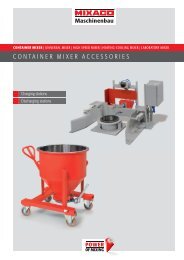
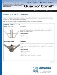
Mechanical Drawing<br />
144 [5.67]<br />
Continuous Gravimetric <strong>Congrav</strong> ® S Model Specifications<br />
9 [0.35]<br />
138 [5.43]<br />
<strong>Congrav</strong> S<br />
Xs<br />
8<br />
9<br />
6<br />
144<br />
[5.67]<br />
138<br />
[5.43]<br />
138<br />
[5.43]<br />
Panel<br />
Cut-Out<br />
Step<br />
244 [9.61]<br />
(without Cables)<br />
Notes:<br />
1) All Dimensions are in Millimeters [Inches]<br />
2) Cooling must be sufficient to prevent exceeding the maximum allowable temperature<br />
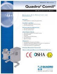
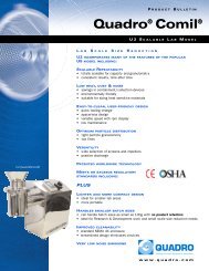
Typical Feeder Electrical Connections<br />
Note: The power wiring and the wiring beyond the Field Wiring Module are by others.<br />
Loss-In-Weight<br />
AC Power<br />
<strong>Congrav</strong>® S Single-Feeder<br />
Controller for Continuous<br />
Loss-In-Weight Feeders (H)<br />
XS1<br />
Field Wiring<br />
Module<br />
RS-422 Digital<br />
AWE<br />
8-12VDC<br />
BT-1094<br />
115VAC<br />
DigiMASS®-2<br />
Digital Load Cell<br />
IDL-F Digital<br />
Load Cell<br />
85-250VAC,<br />
47-63Hz, 1 Phase<br />
Internal Fuse:<br />
2A, Time Delay<br />
XS2<br />
XS4<br />
AC Power<br />
Load<br />
Cell<br />
Motor<br />
AED Digital<br />
Amplifier<br />
10-30VDC<br />
Motor Speed Control<br />
0-10V Analog<br />
Strain Gauge<br />
Load Cell (Analog)<br />
VFD<br />
User I/O<br />
(See User I/O Drawing)<br />
115/230 VAC, 50/60Hz<br />
Weigh Belt<br />
AC Power<br />
<strong>Congrav</strong>® S Single-Feeder<br />
Controller for Continuous or<br />
Batch Weigh Belt Feeders (G)<br />
85-250VAC,<br />
47-63Hz, 1 Phase<br />
Internal Fuse:<br />
2A, Time Delay<br />
XS1<br />
XS2<br />
XS4<br />
AC Power<br />
Field Wiring<br />
Module<br />
RS-422 Digital<br />
Load<br />
Cell<br />
Motor{<br />
AED Digital<br />
Amplifier<br />
10-30VDC<br />
0-25ma Analog<br />
Motor Speed Control<br />
0-10V Analog<br />
Strain Gauge<br />
Load Cell (Analog)<br />
Strain Gauge<br />
Load Cell (Analog)<br />
VFD<br />
Motor Speed Feedback<br />
Digital Tach.<br />
115/230 VAC,<br />
50/60Hz<br />
User I/O<br />
(See User I/O Drawing)<br />
8/04 Supersedes 4/03 Page 3 of 4 Document: 7200-C30-1
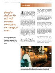
User I/O Connections<br />
Continuous Gravimetric <strong>Congrav</strong> ® S Model Specifications<br />
Note: The power wiring and the wiring beyond the Field Wiring Module are by others.<br />
<strong>Congrav</strong>® S Single-Feeder<br />
Controller for Continuous<br />
Gravimetric Feeders (H, G)<br />
Field Wiring<br />
Module<br />
8 Digital<br />
Inputs<br />
24VDC<br />
Interlock<br />
Stop (Remote)<br />
Start (Remote)<br />
Alarm Reset (Remote)<br />
Refill (H) or AutoTare (G) (Remote)<br />
Gravimetric Discharge Mode (H) (Remote)<br />
Key Switch (Data Entry Lock)<br />
XS1<br />
XS2<br />
XS4<br />
Digital<br />
Outputs<br />
{<br />
3<br />
4<br />
1<br />
24VDC<br />
24VDC<br />
Operation<br />
Alarm (Feeder Cut-Out)<br />
Refill (H) or AutoTare (G)<br />
Feedrate Deviation (Alarm)<br />
Overload (Alarm)<br />
Underload (Alarm)<br />
Alarm Report (Warning Only)<br />
Throughput Pulse<br />
Communications Configurations<br />
Analog<br />
Input<br />
Analog<br />
Output<br />
0-10V Remote Setpoint<br />
0/4-20ma<br />
Actual Value Output<br />
Note: The wiring is by others.<br />
RS-422 Multi-Drop Communications<br />
Up to 9 Slaves<br />
per Master<br />
<strong>Congrav</strong> S<br />
<strong>Congrav</strong> S<br />
<strong>Congrav</strong> S<br />
8<br />
9<br />
8<br />
9<br />
8<br />
9<br />
Xs<br />
6<br />
Xs<br />
6<br />
Xs<br />
6<br />
Step<br />
Step<br />
Step<br />
MASTER<br />
Sets the feedrate for<br />
this ingredient<br />
SLAVE 1<br />
Feedrate for this ingredient<br />
is entered as a percent<br />
of the Master feedrate<br />
(Setpoint or Actual)<br />
SLAVE 2<br />
Feedrate for this ingredient<br />
is entered as a percent<br />
of the Master feedrate<br />
(Setpoint or Actual)<br />
<strong>Congrav</strong> S<br />
Xs<br />
Step<br />
8<br />
9 Profibus-DP Setup Parameters (Read/Write)<br />
Commands (Write)<br />
6<br />
Communications<br />
Status (Read)<br />
<strong>Congrav</strong>® S with optional<br />
Profibus Add-In Card<br />
<strong>Congrav</strong> S<br />
8 9<br />
Xs<br />
6<br />
Step<br />
<strong>Congrav</strong>® S<br />
DataLink Module<br />
115/230VAC<br />
1761-NET-ENI<br />
Module<br />
24VDC<br />
174 CEV 300 10<br />
Module<br />
24VDC<br />
Ethernet/IP<br />
DH+<br />
DF1<br />
Modbus RTU Slave<br />
Ethernet Modbus/TCP<br />
Head Office:<br />
6500 Kestrel Road<br />
Mississauga, Ontario<br />
Canada, L5T 1Z6<br />
Telephone:<br />
Toll Free:<br />
Facsimile:<br />
Email:<br />
(905) 670-2933<br />
(888) 284-4574<br />
(905) 670-2557<br />
sales@brabenderti.com<br />
8/04 Supersedes 4/03 Page 4 of 4 Document: 7200-C30-1