Vacuum heater installation - Foster Wheeler Italiana
Vacuum heater installation - Foster Wheeler Italiana
Vacuum heater installation - Foster Wheeler Italiana

You also want an ePaper? Increase the reach of your titles
YUMPU automatically turns print PDFs into web optimized ePapers that Google loves.
foster 20/7/06 22:24 Page 1<br />
<strong>Vacuum</strong> <strong>heater</strong> <strong>installation</strong><br />
One refinery has proved it is possible to revamp any process unit by modification<br />
and/or replacement of key process equipment in situ. The project was completed in<br />
less than 12 months and included a 350-ton fired <strong>heater</strong> module<br />
Giampiero Caronno<br />
<strong>Foster</strong> <strong>Wheeler</strong> <strong>Italiana</strong> SpA<br />
The JSC Mozyr oil refinery in the<br />
Republic of Belarus recently completed<br />
the <strong>installation</strong> of a new<br />
vacuum distillation <strong>heater</strong>, which had<br />
been assembled directly within the<br />
1800 000 tpy vacuum distillation (UVDM)<br />
unit.<br />
With a challenging schedule of 12<br />
months from contact signature to startup,<br />
the 350-ton fired <strong>heater</strong> fabricated<br />
module was moved onto existing<br />
foundations. Careful project planning<br />
meant it was possible to achieve the<br />
<strong>installation</strong> in less than 30 days, well<br />
within the scheduled vacuum unit<br />
turnaround. The newly installed fired<br />
<strong>heater</strong>s dramatically improved the<br />
process unit performance.<br />
On 3 November 2005, the UVDM unit<br />
was started up after a scheduled unit<br />
turnaround lasting less than 30 days.<br />
During this turnaround, the existing fired<br />
<strong>heater</strong> was replaced with the customdesigned<br />
<strong>Foster</strong> <strong>Wheeler</strong> furnace in order<br />
to optimise process operations and ensure<br />
that all process requirements, and<br />
environmental and refinery demands<br />
were met. A detailed analysis was carried<br />
out with refinery management, process<br />
unit operators and mechanical specialists.<br />
<strong>Foster</strong> <strong>Wheeler</strong> had previously<br />
supplied the refinery with a new<br />
visbreaker <strong>heater</strong>. The JSC Mozyr oil<br />
refinery took this into account during<br />
the evaluations and analysis for a new<br />
<strong>heater</strong> supplier, together with the fact<br />
that <strong>Foster</strong> <strong>Wheeler</strong> had the capability<br />
to carry out this type of refurbishment.<br />
Detailed knowledge of all aspects of<br />
<strong>heater</strong> design was an extremely<br />
important issue. Factors to be taken into<br />
consideration included:<br />
— Plot space for lifting<br />
— Logistics for modules access and<br />
egress for plant and heavy equipment<br />
— Lay-down and working areas.<br />
These factors had to be considered<br />
during the initial planning and<br />
evaluation phase of the project due to<br />
their potential impact on cost and<br />
schedule. Prime challenges for the<br />
project team were:<br />
— Project timing This was critical, as<br />
Bid tender declaration & RFQ 14 August 2004<br />
Contract signature 14 October 2004<br />
Material delivery June–September 2005<br />
New <strong>heater</strong> erection August–October 2005<br />
Old <strong>heater</strong> dismantling 5–12 October 2005<br />
New <strong>heater</strong> module moving 16–18 October 2005<br />
New <strong>heater</strong> piping tie-ins 20–30 October 2005<br />
New <strong>heater</strong> start-up 3 November 2005<br />
Table 1<br />
<strong>Vacuum</strong> <strong>heater</strong> item P-101M — review of key milestones<br />
the turnaround had already been<br />
defined as October/November 2005, less<br />
than two years after the commencement<br />
of feasibility studies<br />
— Feasibility of the project Since the<br />
vacuum unit shutdown period was<br />
short, the construction work had to be<br />
completed in the shortest possible time,<br />
thereby minimising production losses.<br />
In the preliminary analysis, costeffective<br />
and innovative solutions were<br />
identified to safely undertake the<br />
replacement of the fired <strong>heater</strong> in the<br />
shortest time. These solutions ranged<br />
from in situ modifications to full unit<br />
replacement. The ideal solution was to<br />
effect a full fired <strong>heater</strong> unit replacement,<br />
but with the following restrictions:<br />
— Modifications of process and utilities<br />
piping had to be reduced to a minimum,<br />
with no changes to existing foundation<br />
piers<br />
— A new vacuum <strong>heater</strong> needed to be<br />
designed to maintain the new foundation<br />
loads within the allowable values<br />
— The existing steam recovery system<br />
through which the flue gases left the<br />
convection section had to be modified,<br />
and the new <strong>heater</strong> convection section<br />
had to take this factor into account.<br />
A proper tie-in on flue ducts was<br />
required, since the flue gases were to be<br />
sent to the existing concrete stack<br />
through the flue gas ducting system<br />
already in place.<br />
After careful analysis of the various<br />
options, JSC Mozyr oil refinery personnel<br />
were confident that the proposed total<br />
revamp was possible and work<br />
commenced (Table 1). The new furnace<br />
was to be erected in the area next to the<br />
existing fired <strong>heater</strong>, which needed to be<br />
kept in production and operation until<br />
the last day before turnaround.<br />
Main process parameters<br />
Among the various factors driving the<br />
revamp and replacement of the vacuum<br />
<strong>heater</strong>, there were several process<br />
considerations and problems relating to<br />
the operation and efficiency of the<br />
existing furnace. The radiant surface of<br />
the original <strong>heater</strong> was insufficient.<br />
Therefore, the heat flux was too high<br />
when compared with the heat flux value<br />
of 25 500 W/m 2 , which is generally<br />
utilised for current vacuum <strong>heater</strong><br />
<strong>installation</strong>s.<br />
The vertical disposition of the radiant<br />
tubes of the original <strong>heater</strong> was a critical<br />
configuration for the flow pattern inside<br />
the process coil, with local overheating<br />
and high coke build-up in the zone<br />
where vapourisation occurred. The tube<br />
size and the process fluid velocity were<br />
inadequate and the heat-transfer coefficiency<br />
was very low, with a high<br />
fluid film temperature and coke buildup<br />
as a consequence.<br />
The new design was developed on the<br />
basis of the available existing plot area,<br />
and took into consideration the<br />
<strong>installation</strong> of a mixed configuration of<br />
vertically and horizontally disposed<br />
coils. The new <strong>heater</strong> was designed to<br />
present standard and codes, and offered<br />
the following advantages:<br />
— Longer operating periods without<br />
decoking<br />
— Tube size properly selected, taking<br />
www.eptq.com 2006 REVAMPS 00
foster 20/7/06 22:24 Page 2<br />
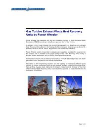
Figures 1 to 3 On-site <strong>heater</strong> assembly<br />
into account the process fluid velocity<br />
— Radiant surface designed according<br />
to 25 500 W/m 2 heat flux max<br />
— Reduction of maintenance activities<br />
for long periods<br />
— High efficiency. Table 2 highlights<br />
the estimated fuel saving based on 8000<br />
hours/year<br />
— Very short payout period due to<br />
both the fuel saving and refurbishment<br />
costs of the existing <strong>heater</strong><br />
— Reduction of NO x emission into the<br />
atmosphere.<br />
Table 2 highlights the following<br />
process factors and parameters<br />
pertaining to the vacuum <strong>heater</strong>:<br />
— Same absorbed process duty<br />
— Lower heat fired and consequently<br />
lower fuel consumption<br />
— Lower radiant heat flux and<br />
consequent milder furnace operation<br />
— Lower excess air<br />
— Lower flue gas emissions.<br />
Project initiation<br />
The JSC Mozyr oil refinery awarded<br />
<strong>Foster</strong> <strong>Wheeler</strong> <strong>Italiana</strong> SpA a fixed-price<br />
lump sum contract for engineering<br />
services and the supply of critical<br />
equipment for the refinery on 14<br />
October 2004, following a bid declared<br />
in compliance with Belarussian law.<br />
There were two immediate major<br />
challenges, which related to project<br />
timing and project feasibility:<br />
— Strong demand for the steel<br />
materials and metals to be used for the<br />
<strong>heater</strong> pressure parts meant delivery<br />
times were under pressure during Q404<br />
— The original 350-ton furnace had to<br />
be rapidly dismantled to allow sufficient<br />
time to install the new unit on the<br />
existing foundations. Also, the new<br />
<strong>heater</strong> had to be pre-assembled to<br />
minimise the erection time, and this had<br />
to be done within close proximity to the<br />
existing plant. This would allow easier<br />
transfer of the new equipment onto the<br />
existing foundations. The system (new<br />
<strong>heater</strong> materials as well as the method of<br />
moving the new <strong>heater</strong>) was designed<br />
and all materials purchased and<br />
fabricated well before the scheduled<br />
turnaround. Careful planning of material<br />
delivery was carried out in order to<br />
optimise construction activities. Actual<br />
delivery of materials started according to<br />
the original contract schedule, thereby<br />
assuring the site that assembly could be<br />
completed in a timely manner.<br />
Job site activities<br />
As soon as the materials arrived on site,<br />
pre-assembly commenced next to the<br />
existing furnace. The <strong>heater</strong> was built<br />
and completely prefabricated with<br />
piping, ladders, stairs, platforms,<br />
instrument, electrics and lighting offplot<br />
on an area immediately adjacent to<br />
the existing <strong>heater</strong>. It was then moved<br />
onto the existing foundations during<br />
the shutdown phase using a skate-type<br />
arrangement on steel rails, as shown in<br />
Figures 1 to 3.<br />
The positioning of the existing piers<br />
and the narrow space around the <strong>heater</strong><br />
meant a hydraulic-type trailer, commonly<br />
used to move such large structures, was<br />
unsuitable for the purpose (Figure 4). The<br />
temporary support base for the erection<br />
of the new <strong>heater</strong> was made by designing<br />
a steel frame that laid directly on the<br />
existing paving without any additional<br />
foundation works (except for a 50mm<br />
thickness grouting for levelling). This area<br />
was previously monitored and tested to<br />
gain the average soil bearing load<br />
00 REVAMPS 2006<br />
www.eptq.com
foster 20/7/06 22:24 Page 3<br />
capacity, as well as all the data required<br />
for the proper sizing of the temporary<br />
support frame and rails.<br />
Both the temporary support frame<br />
and the rail systems were designed to<br />
maximise all field connections by a<br />
bolting joint option to save time during<br />
assembly and disassembly.<br />
While the construction of the new<br />
<strong>heater</strong> was under way and the existing<br />
furnace was still operating, the<br />
construction of the rail system (to<br />
connect the temporary support frame to<br />
the existing <strong>heater</strong> foundations) was<br />
carried out using materials available on<br />
the local market.<br />
Final tie-ins and detailed finalisation<br />
of the rail system were completed after<br />
the dismantling of the existing <strong>heater</strong>.<br />
The special equipment arrived at site<br />
and comprised:<br />
— Eight heavy-duty rolling skates<br />
— Eight hydraulic jacks for vertical<br />
lifting (150mm stroke)<br />
— Four hydraulic jacks for horizontal<br />
translation (150mm stroke)<br />
— One hydraulic switchboard.<br />
The new furnace was built in the<br />
dedicated area inside the process unit<br />
(Figure 5). The JSC Mozyr refinery and<br />
their subcontractors rapidly assembled<br />
the unit. The construction included:<br />
— Radiant steelwork and pressure parts<br />
— Tube supports<br />
— Refractory and burners, ready to be<br />
connected to the fuel systems<br />
— Convection section (inclusive of<br />
soot blowers)<br />
— Part of flue gas duct, which<br />
connected into the existing flue gas<br />
ducting system.<br />
At the end of September 2005, the<br />
refinery and <strong>Foster</strong> <strong>Wheeler</strong> completed<br />
the new furnace construction adjacent<br />
to the previous unit. At the same time,<br />
the main equipment and details<br />
relevant to the movement of the <strong>heater</strong><br />
were finalised, ready for the process unit<br />
shutdown.<br />
Time constraints<br />
The critical dismantling activities of the<br />
existing vacuum <strong>heater</strong> had to be<br />
accomplished in a very short time frame<br />
because of the unit turnaround. The<br />
preparatory works required the<br />
transportation of the new furnace and<br />
disposal of old equipment and materials<br />
to exacting safety standards.<br />
After the existing <strong>heater</strong> was<br />
completely demolished and removed,<br />
the existing piers were checked and<br />
arranged to receive the new <strong>heater</strong> by<br />
installing a special new counter<br />
baseplate in order to avoid the possible<br />
mismatch of bolts. The new <strong>heater</strong> was<br />
then moved from the pre-erection area<br />
to its final position.<br />
On 10 October 2005, after the<br />
original <strong>heater</strong> had been dismantled, it<br />
was necessary to install skidding beams<br />
<strong>Vacuum</strong> <strong>heater</strong> item P -101M Old <strong>heater</strong> New <strong>heater</strong><br />
Absorbed duty, MW 28.624 28.624<br />
Heat fired, MW 42.094 34.907<br />
Net efficiency, % 68.0 83.5<br />
Heat losses, % 2.0 1.5<br />
Radiant heat flux, W/m 2 28.250 24.900<br />
Excess air, % 40 25<br />
Fuel oil consumption, ton/y 30.480 25.280<br />
Fuel oil saving, ton/y 5200<br />
NO x emission, ton/y 145 82<br />
NO x reduction, ton/y 63 (-43.4%)<br />
Table 2<br />
Process factors and parameters pertaining to the vacuum <strong>heater</strong><br />
Figure 4 On-site <strong>heater</strong> assembly<br />
Figure 5 New furnace construction<br />
T<br />
www.eptq.com 2006 REVAMPS 00
foster 20/7/06 22:24 Page 4<br />
Figure 6 Final preparations to new furnace<br />
Fìgure 7 Furnace <strong>installation</strong> prior to startup<br />
between the foundation piling and the<br />
design plate to avoid any foundation<br />
bolt mismatch. Work continued to<br />
finish the preparatory works to enable<br />
smooth transportation of the furnace.<br />
On 15 October 2005, the <strong>heater</strong> was<br />
trial-lifted by hydraulic jacks to briefly<br />
check the system without moving it<br />
horizontally. The following day, the<br />
module was moved horizontally by<br />
pulling at a velocity of about 5m per day<br />
and was finally pushed due to limited<br />
space within the unit. The detailed<br />
sequence of the transportation of the<br />
module can be summarised as follows:<br />
1. Insertion of No. 8 off-vertical<br />
hydraulic jacks under the proper lifting<br />
point on the furnace main beam<br />
2. Furnace lifting for approximately<br />
100mm and placing No. 8 heavy-duty<br />
rolling skates between the furnace main<br />
beam and rails<br />
3. Furnace lowering on the No. 8 heavyduty<br />
rolling skates<br />
4. Placement of No. 4 off-horizontal<br />
hydraulic jack, ready to pull<br />
5. Furnace transportation in successive<br />
pulling steps along the track, 0.5m at<br />
time, until reaching the existing<br />
foundation plinths<br />
6. Furnace lifting and removal of the<br />
No. 8 heavy-duty rolling skates<br />
7. Furnace lowering on the existing<br />
foundation plinths and fixed by welding<br />
to the new counter baseplate<br />
8. Furnace completion and tie-ins<br />
connection (piping, flue gas duct).<br />
Bad weather conditions slowed down<br />
work considerably during the critical<br />
days of moving the <strong>heater</strong>, but the<br />
refinery specialists, their sub-contractors<br />
and <strong>Foster</strong> <strong>Wheeler</strong> allowed the new<br />
vacuum <strong>heater</strong> to be successfully moved<br />
to its final place on 18 October 2005,<br />
exactly one year after contract signature.<br />
Startup was successfully achieved<br />
without any significant problems and<br />
the furnace reached 100% capacity<br />
immediately after completion of the<br />
dry-out cycle.<br />
Process operations at the refinery<br />
started with fuel gas operation, as time<br />
was limited to finalise the fuel oil and<br />
steam system. However, recommendations<br />
were given to allow such a change<br />
into fuel oil operation to go smoothly<br />
and in full accordance with process<br />
parameters and specifications.<br />
With activities planned in advance<br />
and the goal to remain within the 30<br />
days of scheduled vacuum unit<br />
shutdown, there has been a substantial<br />
improvement in operating conditions as<br />
well as in the operating efficiency of the<br />
new furnace of the vacuum unit. The<br />
fired <strong>heater</strong> design capacity was not<br />
increased for specific process considerations<br />
and requirements.<br />
The project clearly proved it is<br />
possible to revamp any process unit by<br />
modification and/or replacement of key<br />
process equipment such as a fired <strong>heater</strong><br />
in situ.<br />
This article is based on a presentation from<br />
the Euro Petroleum Consultants, Russia CIS<br />
Refining & Petrochemicals Equipment<br />
Conference, Moscow, 5–6 April 2006.<br />
Giampiero Caronno is sales manager,<br />
equipment, for <strong>Foster</strong> <strong>Wheeler</strong> <strong>Italiana</strong> SpA<br />
in Milan, Italy. Caronno is responsible for<br />
FWI fired <strong>heater</strong> sales in Russia.<br />
Email: giampiero_caronno@fwceu.com<br />
00 REVAMPS 2006<br />
www.eptq.com