Relaying problems in the connection of a dispersed generating plant ...
Relaying problems in the connection of a dispersed generating plant ...
Relaying problems in the connection of a dispersed generating plant ...

You also want an ePaper? Increase the reach of your titles
YUMPU automatically turns print PDFs into web optimized ePapers that Google loves.
RELAYING PROBLEMS IN THE CONNECTION OF A DISPERSED GENERATING PLANT TO THE<br />
132kV NETWORK<br />
L. Caciolli (*), G. Invernizzi (**), P.F. Lionetto (**)<br />
(*) Gestore della Rete di Trasmissione Nazionale (GRTN), Italy<br />
(**) Foster Wheeler Italiana, Italy<br />
INTRODUCTION<br />
Start<strong>in</strong>g from 1991, with <strong>the</strong> adoption <strong>of</strong> <strong>the</strong> energy<br />
sav<strong>in</strong>g oriented laws N°9/91&N°10/91, new generat<strong>in</strong>g<br />
<strong>plant</strong>s have been set up <strong>in</strong> Italy by Independent Power<br />
Producers to deliver <strong>the</strong> generated electric energy to <strong>the</strong><br />
National Grid. Accord<strong>in</strong>g to <strong>the</strong>se laws, <strong>the</strong> new <strong>plant</strong>s<br />
had to make use ma<strong>in</strong>ly <strong>of</strong> renewable sources or waste<br />
fuel. In case <strong>of</strong> conventional <strong>the</strong>rmal <strong>plant</strong>s <strong>the</strong>y had to<br />
be configured as co-generation <strong>plant</strong>s, as high efficient<br />
use <strong>of</strong> primary fuel was requested. Several <strong>plant</strong>s us<strong>in</strong>g<br />
high efficient gas turb<strong>in</strong>es <strong>in</strong> comb<strong>in</strong>ed cycle<br />
configuration have been connected to 132kV network<br />
when rated above 10MW.<br />
As an aftermath <strong>of</strong> <strong>the</strong> recent liberalisation <strong>of</strong> electric<br />
energy market and <strong>the</strong> privatisation <strong>of</strong> generat<strong>in</strong>g field<br />
stated by <strong>the</strong> law N°79/99 <strong>of</strong> 16/3/99, which<br />
acknowledges <strong>the</strong> UE directive 96/92/CE, new power<br />
<strong>plant</strong>s <strong>of</strong> different size and type will be connected to <strong>the</strong><br />
National Transmission Grid <strong>in</strong> <strong>the</strong> next future. Great<br />
impact on network exploitation and protection<br />
philosophies is expected due to <strong>the</strong> presence <strong>of</strong> <strong>the</strong> new<br />
generat<strong>in</strong>g units <strong>dispersed</strong> on <strong>the</strong> network. As a<br />
consequence, appropriate technical regulations stat<strong>in</strong>g<br />
common rules for private producers and public system<br />
operators are essential to guarantee high levels <strong>of</strong><br />
quality and availability <strong>of</strong> <strong>the</strong> supply to users. The<br />
National Transmission Grid Operator (GRTN “Gestore<br />
della Rete di Trasmissione Nazionale”) is def<strong>in</strong><strong>in</strong>g<br />
detailed technical regulations which make reference to<br />
<strong>the</strong> new national standard CEI 11-32, issued by <strong>the</strong><br />
Italian Electrical Committee (CEI) <strong>in</strong> June 2000 as a<br />
revision <strong>of</strong> <strong>the</strong> previous one published <strong>in</strong> 1993 to take<br />
<strong>in</strong>to account <strong>the</strong> laws 9&10/91.<br />
The new <strong>dispersed</strong> generation will affect ma<strong>in</strong>ly <strong>the</strong><br />
132kV network, which had been planned <strong>in</strong> Italy as<br />
primary distribution system to supply large user <strong>plant</strong>s<br />
and MV distribution network.<br />
Different power flows, which may affect voltage pr<strong>of</strong>ile<br />
and overload l<strong>in</strong>es, are expected; fault duty can <strong>in</strong>crease<br />
up to values exceed<strong>in</strong>g <strong>the</strong> withstand level <strong>of</strong> exist<strong>in</strong>g<br />
components. L<strong>in</strong>e protection sett<strong>in</strong>gs and criteria will be<br />
re-analysed tak<strong>in</strong>g <strong>in</strong>to account <strong>in</strong>-feed effect, possible<br />
power sw<strong>in</strong>gs and generator out-<strong>of</strong>-step conditions.<br />
Moreover, automatic three-phase reclos<strong>in</strong>g with short<br />
dead time (0.3s), which had been <strong>in</strong>stalled to improve<br />
<strong>the</strong> quality <strong>of</strong> supply to <strong>the</strong> loads, may cause generators<br />
out-<strong>of</strong>-phase reclos<strong>in</strong>g: this will make necessary <strong>the</strong><br />
<strong>in</strong>stallation <strong>of</strong> s<strong>in</strong>gle-phase reclos<strong>in</strong>g systems <strong>in</strong>stead <strong>of</strong><br />
three-phase ones.<br />
The paper deals with specific relay<strong>in</strong>g <strong>problems</strong> caused<br />
by <strong>the</strong> <strong>connection</strong> to <strong>the</strong> exist<strong>in</strong>g 132kV network <strong>of</strong> a<br />
private co-generation power <strong>plant</strong>, rated 140MW, and<br />
focuses <strong>the</strong> study performed to achieve a satisfactory<br />
co-ord<strong>in</strong>ation plan between new and exist<strong>in</strong>g protective<br />
relays and to m<strong>in</strong>imise <strong>the</strong> replacement <strong>of</strong> exist<strong>in</strong>g<br />
protections.<br />
SYSTEM CHARACTERISTICS<br />
132kV Network<br />
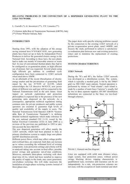
Dur<strong>in</strong>g <strong>the</strong> 70’s and 80’s, <strong>the</strong> Italian 132kV network<br />
was developed as a distribution system. The system,<br />
which is typically a meshed grid, is fed by <strong>the</strong> 380kV<br />
grid via 380/132kV ma<strong>in</strong> stations. Normal operation is<br />
performed by means <strong>of</strong> “load islands”; each island is<br />
made by a number <strong>of</strong> ma<strong>in</strong> l<strong>in</strong>es (“arteries”), usually fed<br />
by two or three separate supplies; HV/MV distribution<br />
substations are connected to <strong>the</strong> l<strong>in</strong>es via two-feedthrough<br />
schemes.<br />
FIGURE 1. General one l<strong>in</strong>e diagram.<br />
L<strong>in</strong>es are equipped with solid state distance relays,<br />
s<strong>in</strong>gle system, four protection zones, without power<br />
sw<strong>in</strong>gs block<strong>in</strong>g device; tripp<strong>in</strong>g characteristic is<br />
quadrilateral type, resistance and reactance can be set<br />
<strong>in</strong>dependently. As a rule, tele-protection schemes are<br />
not used, with <strong>the</strong> exception <strong>of</strong> multi-term<strong>in</strong>al and short
l<strong>in</strong>es (
TABLE 2 - Grid characteristics at connect<strong>in</strong>g po<strong>in</strong>t.<br />
Average voltage value 134 kV<br />
Three-phase fault currents (m<strong>in</strong>/max) 15 / 19 kA<br />
S<strong>in</strong>gle-phase-to-ground fault curr. (m<strong>in</strong>/max) 15 / 18.5 kA<br />
When <strong>the</strong> HV.E-Q52 circuit breaker trips, <strong>the</strong> <strong>plant</strong><br />
automatically switches to “island” operation and trips<br />
one gas turb<strong>in</strong>e and <strong>the</strong> steam turb<strong>in</strong>e generators; <strong>the</strong><br />
second gas turb<strong>in</strong>e generator, with speed governor<br />
automatically switched from droop to frequency control<br />
mode, rema<strong>in</strong>s <strong>in</strong> operation supply<strong>in</strong>g <strong>the</strong> services <strong>of</strong> <strong>the</strong><br />
<strong>plant</strong>.<br />
(referred to <strong>the</strong> network equivalent generator) <strong>in</strong> case <strong>of</strong><br />
three-phase fault at station A. S<strong>in</strong>ce no specific busbar<br />
protections exist, <strong>the</strong> fault is cleared by <strong>the</strong> AC l<strong>in</strong>e<br />
second zone distance relay <strong>in</strong>stalled <strong>in</strong> station C. Torque<br />
rotor angle oscillation amplitude is strictly dependent on<br />
fault clear<strong>in</strong>g time and on generator load and excitation<br />
conditions. The result<strong>in</strong>g critical clear<strong>in</strong>g times <strong>of</strong><br />
generators are 0.35 – 0.4s (over-excited) and 0.25-0.3s<br />
(under-excited).<br />
TRANSIENT PERFORMANCE STUDY AND<br />
PROTECTIVE RELAY CO-ORDINATION<br />
Due to <strong>the</strong> large size <strong>of</strong> generators (3x70MVA) and <strong>the</strong><br />
specific characteristics <strong>of</strong> 132kV network, <strong>the</strong> sett<strong>in</strong>g <strong>of</strong><br />
<strong>the</strong> exist<strong>in</strong>g protections required <strong>the</strong> analysis <strong>of</strong> power<br />
<strong>plant</strong> transient performance. Therefore, a stability study<br />
was performed with <strong>the</strong> follow<strong>in</strong>g ma<strong>in</strong> goals:<br />
− calculate critical clear<strong>in</strong>g times for three-phase faults<br />
on 132kV network, <strong>in</strong> order to state <strong>the</strong> maximum<br />
fault clear<strong>in</strong>g times consistent with generator<br />
stability;<br />
− analyse transient trend <strong>of</strong> impedance and frequency<br />
necessary to set protective relays, <strong>in</strong> order to prevent<br />
false tripp<strong>in</strong>g <strong>of</strong> l<strong>in</strong>e distance relays on power<br />
sw<strong>in</strong>gs and ensure selectivity between <strong>plant</strong> and<br />
network protections;<br />
− verify <strong>the</strong> capability <strong>of</strong> <strong>the</strong> <strong>plant</strong> to switchover to<br />
island operation.<br />
The s<strong>of</strong>tware used for <strong>the</strong> study was “Cymestab” by<br />
CYME Inc.; generators with <strong>the</strong>ir governors and<br />
excitation systems, large <strong>in</strong>duction motors <strong>of</strong> <strong>the</strong> <strong>plant</strong>,<br />
and <strong>the</strong> 132kV network around <strong>the</strong> <strong>plant</strong> were suitably<br />
modelled. Equivalent models <strong>of</strong> 380kV network and<br />
relevant generat<strong>in</strong>g <strong>plant</strong>s were taken <strong>in</strong>to account.<br />
Several disturbances, <strong>of</strong> different type and location,<br />
were simulated, i.e.:<br />
− three-phase faults at different po<strong>in</strong>ts <strong>of</strong> <strong>in</strong>com<strong>in</strong>g<br />
l<strong>in</strong>es to station C, followed by fault clear<strong>in</strong>g and<br />
faulted l<strong>in</strong>e dis<strong>connection</strong>;<br />
− switch-over to island operation supply<strong>in</strong>g a small<br />
part <strong>of</strong> <strong>the</strong> 132 kV network, as a result <strong>of</strong> sudden<br />
grid mesh break<strong>in</strong>g.<br />
The analysis took <strong>in</strong>to account <strong>the</strong> operation with <strong>the</strong><br />
generators over and under-excited (correspond<strong>in</strong>g<br />
respectively to daily and nightly operation), as well as<br />
normal and emergency network configurations (i.e. both<br />
<strong>the</strong> <strong>in</strong>com<strong>in</strong>g l<strong>in</strong>es <strong>in</strong> operation and one out <strong>of</strong> service<br />
for ma<strong>in</strong>tenance).<br />
Due to <strong>the</strong> different source impedance values <strong>of</strong> stations<br />
A and F (about 5Ω and 20Ω), <strong>the</strong> loss <strong>of</strong> <strong>the</strong> AC l<strong>in</strong>e is<br />
<strong>the</strong> most critical case from a stability po<strong>in</strong>t <strong>of</strong> view: <strong>the</strong><br />
equivalent transfer impedance <strong>of</strong> <strong>the</strong> <strong>plant</strong> <strong>in</strong>creases and<br />
susta<strong>in</strong>ed power sw<strong>in</strong>g are to be expected <strong>in</strong> <strong>the</strong> postfault<br />
period. Figure 3 represents <strong>the</strong> trend versus time <strong>of</strong><br />
gas and steam turb<strong>in</strong>e generators “torque rotor angle”<br />
FIGURE 3. Generators torque rotor angle versus time (critical<br />
clear<strong>in</strong>g time:0.35s).<br />
PROTECTION SETTING<br />
Distance relay sett<strong>in</strong>g<br />
The impedance locus as seen by different protections<br />
was plotted <strong>in</strong> <strong>the</strong> X/R diagram to facilitate relay<br />
sett<strong>in</strong>gs. Figure 4 shows <strong>the</strong> impedance loci seen by BF<br />
l<strong>in</strong>e protection <strong>in</strong>stalled <strong>in</strong> station B, <strong>in</strong> case <strong>of</strong> threephase<br />
fault <strong>in</strong> station A cleared <strong>in</strong> 0.35s (refer to <strong>the</strong><br />
transient <strong>of</strong> Figure 3).<br />
FIGURE 4. Station B (l<strong>in</strong>e BF) distance relay R,X diagram.
Figure 5 represents a zoom <strong>of</strong> <strong>the</strong> same locus and <strong>the</strong><br />
quadrilateral operat<strong>in</strong>g characteristic <strong>of</strong> <strong>the</strong> protective<br />
relay <strong>in</strong> station B (first zone only). As dur<strong>in</strong>g generator<br />
power sw<strong>in</strong>gs <strong>the</strong> impedance locus enters <strong>the</strong> relay’s<br />
exist<strong>in</strong>g operat<strong>in</strong>g area, it was necessary to reduce <strong>the</strong><br />
resistive reach below 50Ω (previous sett<strong>in</strong>g) with a<br />
proper marg<strong>in</strong>.<br />
DISTURBANCE TIME TO<br />
REACH 50.5Hz<br />
MAX FREQ. AND<br />
AVERAGE df/dt<br />
100% (*) load reduction 0.17s 51.6Hz 3Hz/s<br />
75% load reduction 0.17s 51.6Hz 2.2Hz/s<br />
50% load reduction 0.5s 51.2Hz 1.2Hz/s<br />
(*) With HV.E-Q52 tripp<strong>in</strong>g and consequent island sequence start<strong>in</strong>g.<br />
Whenever a sudden load reduction greater than 50% <strong>of</strong><br />
<strong>plant</strong> base load is experienced, <strong>the</strong> HV.E-Q52 circuit<br />
breaker trips, thus start<strong>in</strong>g <strong>the</strong> island automatic sequence<br />
that disconnects <strong>the</strong> steam turb<strong>in</strong>e and one gas turb<strong>in</strong>e<br />
and prevents gas turb<strong>in</strong>e motor<strong>in</strong>g (Figure 6).<br />
FIGURE 5. Station B (l<strong>in</strong>e BF) distance relay R,X diagram: a<br />
zoom around <strong>the</strong> zero.<br />
Frequency relay sett<strong>in</strong>g<br />
The power <strong>plant</strong> is requested to operate on restricted<br />
parts <strong>of</strong> <strong>the</strong> 132kV network to ensure supply cont<strong>in</strong>uity<br />
to <strong>the</strong> users <strong>in</strong> case <strong>of</strong> sudden mesh break<strong>in</strong>g. For <strong>the</strong><br />
power <strong>plant</strong>, this situation corresponds to sudden load<br />
reductions, up to full load rejection <strong>in</strong> case <strong>of</strong> very small<br />
residual loads.<br />
The transient performance study <strong>of</strong> <strong>the</strong> <strong>plant</strong> po<strong>in</strong>ted out<br />
that <strong>in</strong> case <strong>of</strong> sudden load reduction greater that 75% <strong>of</strong><br />
base load, motor<strong>in</strong>g <strong>of</strong> gas turb<strong>in</strong>es was to be expected<br />
as a consequence <strong>of</strong> different load shar<strong>in</strong>g among <strong>the</strong><br />
three generators, different <strong>in</strong>ertia constant <strong>of</strong> <strong>the</strong><br />
mach<strong>in</strong>es and different time-response <strong>of</strong> speed<br />
governors: gas turb<strong>in</strong>e generators start to operate as<br />
synchronous motors fed by <strong>the</strong> steam turb<strong>in</strong>e generator.<br />
This operat<strong>in</strong>g condition conflicts not only with turb<strong>in</strong>e<br />
safe operation (<strong>the</strong> anti-motor<strong>in</strong>g relay trips <strong>the</strong><br />
mach<strong>in</strong>e), but also with process requirements (<strong>in</strong><br />
comb<strong>in</strong>ed cycle steam is obta<strong>in</strong>ed from recovery boilers<br />
fed by gas turb<strong>in</strong>e exhausts).<br />
Considered that it is not possible to detect <strong>the</strong> mesh<br />
break<strong>in</strong>g po<strong>in</strong>t a priori, <strong>the</strong> 132kV busbar overfrequency<br />
relay was set to prevent <strong>the</strong> above harmful<br />
situations <strong>in</strong> case <strong>of</strong> operation on very restricted<br />
network islands.<br />
Several frequency trends versus time, correspond<strong>in</strong>g to<br />
sudden switch-over <strong>of</strong> <strong>the</strong> <strong>plant</strong> to different restricted<br />
parts <strong>of</strong> <strong>the</strong> network, were analysed. The sett<strong>in</strong>g <strong>of</strong> overfrequency<br />
relay (f>=50.5Hz, df/dt=1.5Hz/s, t R =0.2s)<br />
was stated on <strong>the</strong> basis <strong>of</strong> <strong>the</strong> results shown <strong>in</strong> Table 3.<br />
TABLE 3 - Frequency trend for different load reduction.<br />
FIGURE 6. Plant frequency versus time (100%, 75%,<br />
50% load reductions).<br />
CONCLUSION<br />
The problem <strong>of</strong> power sw<strong>in</strong>gs as a consequence <strong>of</strong><br />
transient performance <strong>of</strong> generators after fault removal<br />
is well known and easily faced if previously taken <strong>in</strong>to<br />
account <strong>in</strong> <strong>the</strong> plann<strong>in</strong>g stage <strong>of</strong> a transmission network<br />
where large power <strong>plant</strong> are likely to be connected.<br />
On <strong>the</strong> contrary, this may result a problem when power<br />
sw<strong>in</strong>gs occur as a consequence <strong>of</strong> <strong>the</strong> <strong>connection</strong> <strong>of</strong> a<br />
power <strong>plant</strong> on a network planned to operate only<br />
supply<strong>in</strong>g loads. False tripp<strong>in</strong>g <strong>of</strong> l<strong>in</strong>e distance relays is<br />
to be expected with <strong>the</strong> consequent risk <strong>of</strong> network<br />
separation <strong>in</strong> unexpected po<strong>in</strong>ts, thus <strong>in</strong>creas<strong>in</strong>g <strong>the</strong> risk<br />
<strong>of</strong> network blackout.<br />
The paper illustrated <strong>the</strong> benefits obta<strong>in</strong>ed from a<br />
stability study <strong>in</strong> <strong>the</strong> sett<strong>in</strong>g <strong>of</strong> l<strong>in</strong>e distance relays<br />
previously <strong>in</strong>stalled on a 132kV network, where a new<br />
power <strong>plant</strong>, 140MW, was set up.<br />
The simulation <strong>of</strong> several disturbances allowed <strong>the</strong><br />
sett<strong>in</strong>g <strong>of</strong> <strong>the</strong> exist<strong>in</strong>g distance relays without add<strong>in</strong>g<br />
any power-sw<strong>in</strong>g block<strong>in</strong>g function.<br />
The <strong>plant</strong> has been <strong>in</strong> operation for two years: few<br />
disturbances on <strong>the</strong> network have been experienced so<br />
far and no unwanted tripp<strong>in</strong>g <strong>of</strong> distance relays<br />
occurred.