00809-0100-4772, Rev DA
00809-0100-4772, Rev DA
00809-0100-4772, Rev DA

You also want an ePaper? Increase the reach of your titles
YUMPU automatically turns print PDFs into web optimized ePapers that Google loves.
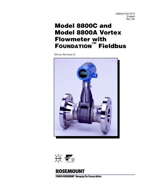
Model 8800C and<br />
Model 8800A Vortex<br />
Flowmeter with<br />
FOUN<strong>DA</strong>TION Fieldbus<br />
(Device <strong>Rev</strong>ision 2)<br />
<strong>00809</strong>-<strong>0100</strong>-<strong>4772</strong><br />
English<br />
<strong>Rev</strong>. <strong>DA</strong>
PRINTED<br />
Product Manual<br />
Model 8800C and Model 8800A<br />
Vortex Flowmeter with<br />
FOUN<strong>DA</strong>TION Fieldbus<br />
(Device <strong>Rev</strong>ision 2)<br />
NOTICE<br />
Read this manual before working with the product. For personal and system<br />
safety, and for optimum product performance, make sure you thoroughly<br />
understand the contents before installing, using, or maintaining this product.<br />
Within the United States, Rosemount Inc. has two toll-free assistance numbers.<br />
Customer Central: 1-800-999-9307 (7:00 a.m. to 7:00 p.m. CST)<br />
Technical support, quoting, and order-related questions.<br />
North American 1-800-654-7768 (24 hours a day – Includes Canada)<br />
Response Center: Equipment service needs.<br />
For equipment service or support needs outside the United States, contact your<br />
local Rosemount representative.<br />
The products described in this document are NOT designed for nuclearqualified<br />
applications.<br />
Using non-nuclear qualified products in applications that require nuclearqualified<br />
hardware or products may cause inaccurate readings.<br />
For information on Rosemount nuclear-qualified products, contact your local<br />
Rosemount Sales Representative.<br />
May be protected by one or more of the following U.S. Patent Nos.4,464,936; 4,926,695. May depend on<br />
model. Other foreign patents issued and pending.<br />
SNF-0004<br />
Fisher-Rosemount Flow<br />
Groeneveldselaan 6-8<br />
3903 AZ Veenendaal<br />
The Netherlands<br />
Tel 31 (0) 318 549 549<br />
Fax 31 (0) 318 549 559<br />
Tel 0800-966 180 (U.K. only)<br />
Fax 0800-966 181 (U.K. only)<br />
Rosemount Inc.<br />
8200 Market Boulevard<br />
Chanhassen, MN 55317 USA<br />
Tel 1-800-999-9307<br />
Fax (612) 949-7001<br />
© 2000 Rosemount Inc.<br />
IN<br />
U.S. A.<br />
Rosemount, the Rosemount logotype, Fisher-Rosemount, Managing the Process Better,<br />
and PlantWeb are marks of one of the Fisher-Rosemount group of companies.<br />
FOUN<strong>DA</strong>TION is a trademark of the Fieldbus Foundation.<br />
Hastelloy and Hastelloy C-22 are registered trademarks of Haynes International<br />
All other marks are the property of their respective owners.<br />
COVER PHOTO: 8800-8800C912 — Model 8800C Vortex Flowmeter With FOUN<strong>DA</strong>TION Fieldbus<br />
Fisher-Rosemount satisfies all obligations coming from legislation<br />
to harmonize product requirements in the European Union.<br />
http://www.rosemount.com
Table of Contents<br />
IMPORTANT<br />
Procedures and instructions in this manual may require special precautions to<br />
ensure the safety of the personnel performing the operations. Refer to the<br />
safety messages at the beginning of each section before performing<br />
any operations.<br />
SECTION 1<br />
Introduction<br />
How to Use This Manual . . . . . . . . . . . . . . . . . . . . . . . . . . . . . . . .1-1<br />
Safety Messages . . . . . . . . . . . . . . . . . . . . . . . . . . . . . . . . . . . . . . .1-2<br />
FOUN<strong>DA</strong>TION Fieldbus Technology. . . . . . . . . . . . . . . . . . . . . 1-2<br />
SECTION 2<br />
Installation<br />
Safety Messages . . . . . . . . . . . . . . . . . . . . . . . . . . . . . . . . . . . . . . .2-1<br />
General Considerations . . . . . . . . . . . . . . . . . . . . . . . . . . . . . . . . .2-1<br />
Flowmeter Sizing . . . . . . . . . . . . . . . . . . . . . . . . . . . . . . .2-1<br />
Flowmeter Orientation . . . . . . . . . . . . . . . . . . . . . . . . . . . . . 2-2<br />
Vertical Installation . . . . . . . . . . . . . . . . . . . . . . . . . . . . .2-2<br />
High-Temperature Installations . . . . . . . . . . . . . . . . . . .2-2<br />
Steam Installations . . . . . . . . . . . . . . . . . . . . . . . . . . . . .2-2<br />
Upstream/Downstream Piping . . . . . . . . . . . . . . . . . . . . .2-3<br />
Pressure and Temperature Transmitter Location . . . . .2-3<br />
Wetted Material Selection . . . . . . . . . . . . . . . . . . . . . . . . . . . 2-3<br />
Environmental Considerations . . . . . . . . . . . . . . . . . . . . . . . 2-3<br />
Hazardous Locations . . . . . . . . . . . . . . . . . . . . . . . . . . . . . . . . . . .2-3<br />
Hardware Configuration . . . . . . . . . . . . . . . . . . . . . . . . . . . . 2-4<br />
Simulate Enable . . . . . . . . . . . . . . . . . . . . . . . . . . . . . . . .2-4<br />
Transmitter Security . . . . . . . . . . . . . . . . . . . . . . . . . . . .2-4<br />
LCD Indicator Option . . . . . . . . . . . . . . . . . . . . . . . . . . . . . . 2-5<br />
Installation Tasks . . . . . . . . . . . . . . . . . . . . . . . . . . . . . . . . . . . . .2-5<br />
Handling . . . . . . . . . . . . . . . . . . . . . . . . . . . . . . . . . . . . . . . . . 2-5<br />
Flow Direction . . . . . . . . . . . . . . . . . . . . . . . . . . . . . . . . . . . . 2-5<br />
Gaskets . . . . . . . . . . . . . . . . . . . . . . . . . . . . . . . . . . . . . . . . . . 2-5<br />
Flange Bolts . . . . . . . . . . . . . . . . . . . . . . . . . . . . . . . . . . . . . . 2-5<br />
Wafer-Style Flowmeter Alignment and Mounting . . . . . . . . 2-7<br />
Spacers . . . . . . . . . . . . . . . . . . . . . . . . . . . . . . . . . . . . . . .2-7<br />
Flanged-Style Flowmeter Mounting . . . . . . . . . . . . . . . . . . . 2-9<br />
Flowmeter Grounding . . . . . . . . . . . . . . . . . . . . . . . . . . . . . . 2-9<br />
Electronics Considerations . . . . . . . . . . . . . . . . . . . . . . . . . . 2-9<br />
High-Temperature Installations . . . . . . . . . . . . . . . . . .2-10<br />
Conduit Connections . . . . . . . . . . . . . . . . . . . . . . . . . . . . . . 2-10<br />
High-Point Installation . . . . . . . . . . . . . . . . . . . . . . . . . . . . 2-10<br />
Cable Gland . . . . . . . . . . . . . . . . . . . . . . . . . . . . . . . . . . . . . 2-10<br />
Electrical Considerations . . . . . . . . . . . . . . . . . . . . . . . . . . . . . .2-19<br />
Power Supply . . . . . . . . . . . . . . . . . . . . . . . . . . . . . . . . . . . . 2-19<br />
Power Conditioning . . . . . . . . . . . . . . . . . . . . . . . . . . . . . . . 2-19<br />
Field Wiring . . . . . . . . . . . . . . . . . . . . . . . . . . . . . . . . . . . . . 2-19<br />
Transmitter Wiring Connection . . . . . . . . . . . . . . . . . . .2-19<br />
Remote Electronics. . . . . . . . . . . . . . . . . . . . . . . . . . . . . . . . 2-20<br />
Mounting . . . . . . . . . . . . . . . . . . . . . . . . . . . . . . . . . . . . .2-20<br />
Cable Connections . . . . . . . . . . . . . . . . . . . . . . . . . . . . .2-21<br />
i
Calibration . . . . . . . . . . . . . . . . . . . . . . . . . . . . . . . . . . . . . . 2-22<br />
Software Configuration . . . . . . . . . . . . . . . . . . . . . . . . . . . . . . . .2-22<br />
Tagging . . . . . . . . . . . . . . . . . . . . . . . . . . . . . . . . . . . . . . . . . 2-22<br />
SECTION 3<br />
Flowmeter Operation<br />
Overview . . . . . . . . . . . . . . . . . . . . . . . . . . . . . . . . . . . . . . . . . . . .3-1<br />
Assigning Device Tag and Node Address . . . . . . . . . . . . . . . . . . .3-2<br />
Configuring the Transducer Block . . . . . . . . . . . . . . . . . . . . . . . .3-2<br />
Flow-Specific Block Configuration . . . . . . . . . . . . . . . . . . . . . . . .3-2<br />
AI Block . . . . . . . . . . . . . . . . . . . . . . . . . . . . . . . . . . . . . . . . . 3-2<br />
General Block Configuration . . . . . . . . . . . . . . . . . . . . . . . . . . . . .3-3<br />
Configuring Links and Scheduling Block Execution . . . . . . . . . .3-3<br />
Cascade Control . . . . . . . . . . . . . . . . . . . . . . . . . . . . . . . .3-4<br />
SECTION 4<br />
Transducer Block<br />
Overview . . . . . . . . . . . . . . . . . . . . . . . . . . . . . . . . . . . . . . . . . . . .4-1<br />
Channel Definitions . . . . . . . . . . . . . . . . . . . . . . . . . . . . . . . . 4-1<br />
Quick Transducer Block Configuration Guide . . . . . . . . . . . 4-1<br />
Configuration Order . . . . . . . . . . . . . . . . . . . . . . . . . . . . .4-2<br />
Parameters and Descriptions . . . . . . . . . . . . . . . . . . . . . . . . 4-4<br />
Block/Transducer Errors . . . . . . . . . . . . . . . . . . . . . . . . . . . . 4-8<br />
Diagnostics . . . . . . . . . . . . . . . . . . . . . . . . . . . . . . . . . . . . . . . 4-9<br />
Alarm Detection . . . . . . . . . . . . . . . . . . . . . . . . . . . . . . . . . . 4-10<br />
Status Handling . . . . . . . . . . . . . . . . . . . . . . . . . . . . . . . . . . 4-10<br />
Troubleshooting . . . . . . . . . . . . . . . . . . . . . . . . . . . . . . . . . . 4-10<br />
Flow Units . . . . . . . . . . . . . . . . . . . . . . . . . . . . . . . . . . . . . . . . . .4-10<br />
Standard/Normal Flow Units . . . . . . . . . . . . . . . . . . . . . . . 4-10<br />
Transducer Block . . . . . . . . . . . . . . . . . . . . . . . . . . . . . . . . . . . . .4-11<br />
Process Variables (PV) . . . . . . . . . . . . . . . . . . . . . . . . . . . . . 4-11<br />
PV Value . . . . . . . . . . . . . . . . . . . . . . . . . . . . . . . . . . . . .4-11<br />
Sensor Serial Number . . . . . . . . . . . . . . . . . . . . . . . . . .4-11<br />
Sensor Range . . . . . . . . . . . . . . . . . . . . . . . . . . . . . . . . .4-11<br />
PV Range . . . . . . . . . . . . . . . . . . . . . . . . . . . . . . . . . . . . .4-11<br />
Basic Setup . . . . . . . . . . . . . . . . . . . . . . . . . . . . . . . . . . . . . . 4-11<br />
Pipe I.D. . . . . . . . . . . . . . . . . . . . . . . . . . . . . . . . . . . . . . .4-11<br />
Service Type . . . . . . . . . . . . . . . . . . . . . . . . . . . . . . . . . .4-11<br />
Process Temperature . . . . . . . . . . . . . . . . . . . . . . . . . . .4-11<br />
Process Density . . . . . . . . . . . . . . . . . . . . . . . . . . . . . . . .4-11<br />
Damping . . . . . . . . . . . . . . . . . . . . . . . . . . . . . . . . . . . . .4-11<br />
Flow Units . . . . . . . . . . . . . . . . . . . . . . . . . . . . . . . . . . . . . . 4-11<br />
Density Ratio . . . . . . . . . . . . . . . . . . . . . . . . . . . . . . . . .4-11<br />
Process Conditions . . . . . . . . . . . . . . . . . . . . . . . . . . . . .4-12<br />
Base Conditions . . . . . . . . . . . . . . . . . . . . . . . . . . . . . . .4-12<br />
Sensor . . . . . . . . . . . . . . . . . . . . . . . . . . . . . . . . . . . . . . . . . . 4-12<br />
Pipe I.D. . . . . . . . . . . . . . . . . . . . . . . . . . . . . . . . . . . . . . .4-12<br />
Service Type . . . . . . . . . . . . . . . . . . . . . . . . . . . . . . . . . .4-13<br />
Reference K-Factor . . . . . . . . . . . . . . . . . . . . . . . . . . . . .4-13<br />
Installation Effects . . . . . . . . . . . . . . . . . . . . . . . . . . . . .4-13<br />
Compensated K-factor . . . . . . . . . . . . . . . . . . . . . . . . . .4-13<br />
Meter Body Number . . . . . . . . . . . . . . . . . . . . . . . . . . . .4-13<br />
Process Temperature . . . . . . . . . . . . . . . . . . . . . . . . . . .4-13<br />
Wetted Material . . . . . . . . . . . . . . . . . . . . . . . . . . . . . . .4-13<br />
Flange Type . . . . . . . . . . . . . . . . . . . . . . . . . . . . . . . . . . .4-14<br />
ii
Filtering . . . . . . . . . . . . . . . . . . . . . . . . . . . . . . . . . . . . . . . . 4-14<br />
Flow Rate Value . . . . . . . . . . . . . . . . . . . . . . . . . . . . . . .4-14<br />
Shedding Frequency . . . . . . . . . . . . . . . . . . . . . . . . . . . .4-14<br />
Sensor Signal Strength . . . . . . . . . . . . . . . . . . . . . . . . . .4-14<br />
Lowpass Corner . . . . . . . . . . . . . . . . . . . . . . . . . . . . . . .4-14<br />
Low Flow Cut . . . . . . . . . . . . . . . . . . . . . . . . . . . . . . . . .4-14<br />
Filter Trigger Level . . . . . . . . . . . . . . . . . . . . . . . . . . . .4-14<br />
Filter Auto Adjust . . . . . . . . . . . . . . . . . . . . . . . . . . . . . .4-15<br />
Required Process Density . . . . . . . . . . . . . . . . . . . . . . . .4-15<br />
Display . . . . . . . . . . . . . . . . . . . . . . . . . . . . . . . . . . . . . . . . . 4-15<br />
Modes . . . . . . . . . . . . . . . . . . . . . . . . . . . . . . . . . . . . . . . . . . 4-15<br />
Target Mode . . . . . . . . . . . . . . . . . . . . . . . . . . . . . . . . . .4-15<br />
Flow Simulation . . . . . . . . . . . . . . . . . . . . . . . . . . . . . . .4-15<br />
Flow . . . . . . . . . . . . . . . . . . . . . . . . . . . . . . . . . . . . . . . . .4-15<br />
Shedding Frequency (Secondary Value) . . . . . . . . . . . .4-15<br />
Shedding Frequency at URV . . . . . . . . . . . . . . . . . . . . .4-15<br />
Simulation Control . . . . . . . . . . . . . . . . . . . . . . . . . . . . .4-15<br />
Simulation Units . . . . . . . . . . . . . . . . . . . . . . . . . . . . . .4-16<br />
Simulation Ramp Period . . . . . . . . . . . . . . . . . . . . . . . .4-16<br />
SECTION 5<br />
Resource Block<br />
Overview . . . . . . . . . . . . . . . . . . . . . . . . . . . . . . . . . . . . . . . . . . . .5-1<br />
Definition . . . . . . . . . . . . . . . . . . . . . . . . . . . . . . . . . . . . . . . . 5-1<br />
Parameters and Descriptions . . . . . . . . . . . . . . . . . . . . . . . . . . . .5-1<br />
Block Errors . . . . . . . . . . . . . . . . . . . . . . . . . . . . . . . . . . . . . . 5-4<br />
Modes . . . . . . . . . . . . . . . . . . . . . . . . . . . . . . . . . . . . . . . . . . . 5-4<br />
Alarm Detection . . . . . . . . . . . . . . . . . . . . . . . . . . . . . . . . . . . 5-5<br />
Status Handling . . . . . . . . . . . . . . . . . . . . . . . . . . . . . . . . . . . 5-5<br />
VCR . . . . . . . . . . . . . . . . . . . . . . . . . . . . . . . . . . . . . . . . . . . . . 5-5<br />
Troubleshooting . . . . . . . . . . . . . . . . . . . . . . . . . . . . . . . . . . . 5-5<br />
SECTION 6<br />
Maintenance and<br />
Troubleshooting<br />
Safety Messages . . . . . . . . . . . . . . . . . . . . . . . . . . . . . . . . . . . . . . .6-1<br />
Troubleshooting Tables . . . . . . . . . . . . . . . . . . . . . . . . . . . . . . . . .6-2<br />
Advanced<br />
Troubleshooting . . . . . . . . . . . . . . . . . . . . . . . . . . . . . . . . . . . . . . .6-4<br />
TP1 . . . . . . . . . . . . . . . . . . . . . . . . . . . . . . . . . . . . . . . . . . . . . .6-4<br />
Shedding Frequency Out . . . . . . . . . . . . . . . . . . . . . . . . . . . . 6-6<br />
Hardware Maintenance . . . . . . . . . . . . . . . . . . . . . . . . . . . . . . . . .6-7<br />
Replacing the FOUN<strong>DA</strong>TION Fieldbus<br />
Terminal Block in the Housing . . . . . . . . . . . . . . . . . . . . . . . 6-8<br />
Replacing the FOUN<strong>DA</strong>TION Fieldbus Electronics Boards . . 6-9<br />
Replacing the FOUN<strong>DA</strong>TION Fieldbus Electronics Housing 6-10<br />
Replacing the Sensor . . . . . . . . . . . . . . . . . . . . . . . . . . . . . . .6-12<br />
Tools Needed . . . . . . . . . . . . . . . . . . . . . . . . . . . . . . . . . .6-12<br />
Sensor Compatibility Guide . . . . . . . . . . . . . . . . . . . . . .6-13<br />
Replacing the<br />
Sensor: Removable and Integral Support Tubes . . . . . . . . .6-14<br />
Removable Support Tube<br />
(for 1 /2- to 4-in. wafer meters and all flanged meters) . .6-14<br />
Integral Support Mount (for 6- to 8-in. wafer meters) .6-15<br />
Cleaning the Sealing Surface . . . . . . . . . . . . . . . . . . . . .6-16<br />
Sensor Installation . . . . . . . . . . . . . . . . . . . . . . . . . . . . .6-17<br />
iii
Remote Electronics Procedure . . . . . . . . . . . . . . . . . . . . . . .6-19<br />
Disconnect the Coaxial Cable at the Meter . . . . . . . . . .6-19<br />
Detach the Meter Adapter . . . . . . . . . . . . . . . . . . . . . . .6-20<br />
Attach the Meter Adapter . . . . . . . . . . . . . . . . . . . . . . .6-20<br />
Connect the Coaxial Cable at the Meter . . . . . . . . . . . .6-20<br />
Coaxial Cable at the Electronics Housing . . . . . . . . . . . . . .6-21<br />
Disconnect the Coaxial Cable from the Electronics<br />
Housing . . . . . . . . . . . . . . . . . . . . . . . . . . . . . . . . . . . . . .6-21<br />
Remove the Coaxial Cable . . . . . . . . . . . . . . . . . . . . . . .6-21<br />
Attach the Coaxial Cable . . . . . . . . . . . . . . . . . . . . . . . .6-21<br />
Connect the Coaxial Cable . . . . . . . . . . . . . . . . . . . . . . .6-21<br />
Changing the FOUN<strong>DA</strong>TION Fieldbus Housing Orientation 6-22<br />
Return of Material . . . . . . . . . . . . . . . . . . . . . . . . . . . . . . . . . . . .6-23<br />
SECTION 7<br />
Options<br />
Safety Messages . . . . . . . . . . . . . . . . . . . . . . . . . . . . . . . . . . . . . . .7-1<br />
LCD Indicator . . . . . . . . . . . . . . . . . . . . . . . . . . . . . . . . . . . . . . . .7-1<br />
Installing the Indicator . . . . . . . . . . . . . . . . . . . . . . . . . . . . . 7-3<br />
Diagnostic Messages . . . . . . . . . . . . . . . . . . . . . . . . . . . . . . . 7-4<br />
SECTION 8<br />
Specifications<br />
Specifications . . . . . . . . . . . . . . . . . . . . . . . . . . . . . . . . . . . . . . . . .8-1<br />
Functional Specifications. . . . . . . . . . . . . . . . . . . . . . . . . . . . 8-1<br />
Line Sizes . . . . . . . . . . . . . . . . . . . . . . . . . . . . . . . . . . . . .8-1<br />
Measurable Flow Rates . . . . . . . . . . . . . . . . . . . . . . . . . .8-1<br />
Process Temperature Limits . . . . . . . . . . . . . . . . . . . . . .8-2<br />
Ambient Temperature Limits . . . . . . . . . . . . . . . . . . . . .8-2<br />
Pressure Loss . . . . . . . . . . . . . . . . . . . . . . . . . . . . . . . . . .8-7<br />
Minimum Back Pressure (Liquids) . . . . . . . . . . . . . . . . .8-7<br />
Response Time . . . . . . . . . . . . . . . . . . . . . . . . . . . . . . . . .8-7<br />
Turn-on Time . . . . . . . . . . . . . . . . . . . . . . . . . . . . . . . . . .8-7<br />
Overrange Capability . . . . . . . . . . . . . . . . . . . . . . . . . . . .8-8<br />
Flow Calibration . . . . . . . . . . . . . . . . . . . . . . . . . . . . . . . .8-8<br />
Status . . . . . . . . . . . . . . . . . . . . . . . . . . . . . . . . . . . . . . . .8-8<br />
Foundation Fieldbus Specifications . . . . . . . . . . . . . . . . . . . 8-8<br />
Virtual Communications Relationships (VCRs) . . . . . . .8-8<br />
Performance Specifications . . . . . . . . . . . . . . . . . . . . . . . . . . 8-8<br />
Accuracy . . . . . . . . . . . . . . . . . . . . . . . . . . . . . . . . . . . . . .8-8<br />
Process Temperature Effect . . . . . . . . . . . . . . . . . . . . . . .8-9<br />
Ambient Temperature Effect . . . . . . . . . . . . . . . . . . . . . .8-9<br />
Vibration Effect . . . . . . . . . . . . . . . . . . . . . . . . . . . . . . . .8-10<br />
Physical Specifications. . . . . . . . . . . . . . . . . . . . . . . . . . . . . 8-10<br />
NACE Compliance . . . . . . . . . . . . . . . . . . . . . . . . . . . . .8-10<br />
Electrical Connections . . . . . . . . . . . . . . . . . . . . . . . . . .8-10<br />
Nonwetted Materials . . . . . . . . . . . . . . . . . . . . . . . . . . .8-10<br />
Process-Wetted Materials . . . . . . . . . . . . . . . . . . . . . . . .8-11<br />
Process Connections . . . . . . . . . . . . . . . . . . . . . . . . . . . .8-11<br />
Mounting . . . . . . . . . . . . . . . . . . . . . . . . . . . . . . . . . . . . .8-11<br />
Pipe Length Requirements . . . . . . . . . . . . . . . . . . . . . . .8-11<br />
Tagging . . . . . . . . . . . . . . . . . . . . . . . . . . . . . . . . . . . . . .8-11<br />
Flow Calibration Information . . . . . . . . . . . . . . . . . . . .8-11<br />
Ordering Information . . . . . . . . . . . . . . . . . . . . . . . . . . . . . . . . .8-12<br />
iv
Configuration Data Sheet (CDS) . . . . . . . . . . . . . . . . . . . . . . . .8-14<br />
Item . . . . . . . . . . . . . . . . . . . . . . . . . . . . . . . . . . . . . . . . .8-14<br />
U.S. Unit (SI Unit) . . . . . . . . . . . . . . . . . . . . . . . . . . . . .8-14<br />
SECTION 9<br />
Electronics Verification<br />
Safety Messages . . . . . . . . . . . . . . . . . . . . . . . . . . . . . . . . . . . . . . .9-1<br />
Electronics Verification . . . . . . . . . . . . . . . . . . . . . . . . . . . . . . . . .9-2<br />
Electronics Verification Using Flow Simulation Mode . . . . .9-2<br />
Fixed Flow Rate Simulation . . . . . . . . . . . . . . . . . . . . . . . . . .9-2<br />
Varying Flow Rate Simulation . . . . . . . . . . . . . . . . . . . . . . . .9-2<br />
Exiting Flow Simulation . . . . . . . . . . . . . . . . . . . . . . . . . . . . 9-2<br />
Electronics Verification Using an External Frequency<br />
Generator . . . . . . . . . . . . . . . . . . . . . . . . . . . . . . . . . . . . . . . . .9-3<br />
Tools Needed . . . . . . . . . . . . . . . . . . . . . . . . . . . . . . . . . . .9-3<br />
Calculating Output Variables with Known Input Frequency 9-4<br />
User Defined Verification Frequencies . . . . . . . . . . . . . . . . . 9-5<br />
Examples . . . . . . . . . . . . . . . . . . . . . . . . . . . . . . . . . . . . . . . . . . . .9-7<br />
Examples: English Units . . . . . . . . . . . . . . . . . . . . . . . . . . . . 9-7<br />
Examples: SI Units . . . . . . . . . . . . . . . . . . . . . . . . . . . . . . . . 9-9<br />
APPENDIX A<br />
FOUN<strong>DA</strong>TION fieldbus<br />
Technology and<br />
Fieldbus<br />
Function Blocks<br />
Overview . . . . . . . . . . . . . . . . . . . . . . . . . . . . . . . . . . . . . . . . . . . A-1<br />
Introduction . . . . . . . . . . . . . . . . . . . . . . . . . . . . . . . . . . . . . . . . . A-1<br />
Function Blocks . . . . . . . . . . . . . . . . . . . . . . . . . . . . . . . . . . . A-1<br />
Device Descriptions . . . . . . . . . . . . . . . . . . . . . . . . . . . . . . . . A-2<br />
Block Operation . . . . . . . . . . . . . . . . . . . . . . . . . . . . . . . . . . . . . . A-3<br />
Instrument-Specific Function Blocks . . . . . . . . . . . . . . . . . . A-3<br />
Resource Blocks . . . . . . . . . . . . . . . . . . . . . . . . . . . . . . . A-3<br />
Transducer Blocks . . . . . . . . . . . . . . . . . . . . . . . . . . . . . A-3<br />
Alerts. . . . . . . . . . . . . . . . . . . . . . . . . . . . . . . . . . . . . . . . . . . . A-3<br />
Network communication . . . . . . . . . . . . . . . . . . . . . . . . . . . . . . . A-3<br />
Link Active Scheduler (LAS) . . . . . . . . . . . . . . . . . . . . . . . . . A-4<br />
Device Addressing . . . . . . . . . . . . . . . . . . . . . . . . . . . . . . . . . A-5<br />
Scheduled Transfers. . . . . . . . . . . . . . . . . . . . . . . . . . . . . . . . A-5<br />
Unscheduled Transfers . . . . . . . . . . . . . . . . . . . . . . . . . . . . . A-6<br />
Function Block Scheduling . . . . . . . . . . . . . . . . . . . . . . . . . . A-7<br />
APPENDIX B<br />
Analog Input (AI)<br />
Function Block<br />
Simulation . . . . . . . . . . . . . . . . . . . . . . . . . . . . . . . . . . . . . . . B-3<br />
Filtering . . . . . . . . . . . . . . . . . . . . . . . . . . . . . . . . . . . . . . . . . B-4<br />
Signal Conversion . . . . . . . . . . . . . . . . . . . . . . . . . . . . . . . . . B-5<br />
Direct . . . . . . . . . . . . . . . . . . . . . . . . . . . . . . . . . . . . . . . . B-5<br />
Indirect . . . . . . . . . . . . . . . . . . . . . . . . . . . . . . . . . . . . . . B-5<br />
Indirect Square Root . . . . . . . . . . . . . . . . . . . . . . . . . . . . B-6<br />
Block Errors . . . . . . . . . . . . . . . . . . . . . . . . . . . . . . . . . . . . . . B-6<br />
Modes . . . . . . . . . . . . . . . . . . . . . . . . . . . . . . . . . . . . . . . . . . . B-6<br />
Alarm Detection . . . . . . . . . . . . . . . . . . . . . . . . . . . . . . . . . . . B-7<br />
Status Handling . . . . . . . . . . . . . . . . . . . . . . . . . . . . . . . . . . . B-7<br />
Advanced Features. . . . . . . . . . . . . . . . . . . . . . . . . . . . . . . . . B-8<br />
Application Information. . . . . . . . . . . . . . . . . . . . . . . . . . . . . B-8<br />
Application Example: Temperature Transmitter . . . . . B-8<br />
Situation . . . . . . . . . . . . . . . . . . . . . . . . . . . . . . . . . . . . . B-8<br />
Solution . . . . . . . . . . . . . . . . . . . . . . . . . . . . . . . . . . . . . . B-8<br />
v
Application Example: Pressure Transmitter used to Measure Level<br />
in an Open Tank . . . . . . . . . . . . . . . . . . . . . . . . . . . . . . . B-9<br />
Situation #1 . . . . . . . . . . . . . . . . . . . . . . . . . . . . . . . . . . . B-9<br />
Solution to Situation #1 . . . . . . . . . . . . . . . . . . . . . . . . . B-9<br />
Situation #2 . . . . . . . . . . . . . . . . . . . . . . . . . . . . . . . . . . B-10<br />
Solution . . . . . . . . . . . . . . . . . . . . . . . . . . . . . . . . . . . . . B-10<br />
Application Example:<br />
Differential Pressure Transmitter to Measure Flow . B-11<br />
Situation . . . . . . . . . . . . . . . . . . . . . . . . . . . . . . . . . . . . B-11<br />
Solution . . . . . . . . . . . . . . . . . . . . . . . . . . . . . . . . . . . . . B-11<br />
Troubleshooting . . . . . . . . . . . . . . . . . . . . . . . . . . . . . . . . . . B-12<br />
APPENDIX C<br />
PID Function Block<br />
Setpoint Selection and Limiting . . . . . . . . . . . . . . . . . . . . . . C-6<br />
Filtering . . . . . . . . . . . . . . . . . . . . . . . . . . . . . . . . . . . . . . . . . C-6<br />
Feedforward Calculation . . . . . . . . . . . . . . . . . . . . . . . . . . . . C-6<br />
Tracking . . . . . . . . . . . . . . . . . . . . . . . . . . . . . . . . . . . . . . . . . C-6<br />
Output Selection and Limiting . . . . . . . . . . . . . . . . . . . . . . . C-7<br />
Bumpless Transfer and Setpoint Tracking. . . . . . . . . . . . . . C-7<br />
PID Equation Structures . . . . . . . . . . . . . . . . . . . . . . . . . . . . C-7<br />
<strong>Rev</strong>erse and Direct Action . . . . . . . . . . . . . . . . . . . . . . . . . . . C-8<br />
Reset Limiting . . . . . . . . . . . . . . . . . . . . . . . . . . . . . . . . . . . . C-8<br />
Block Errors . . . . . . . . . . . . . . . . . . . . . . . . . . . . . . . . . . . . . . C-8<br />
Modes . . . . . . . . . . . . . . . . . . . . . . . . . . . . . . . . . . . . . . . . . . . C-8<br />
Alarm Detection . . . . . . . . . . . . . . . . . . . . . . . . . . . . . . . . . . . C-9<br />
Status Handling . . . . . . . . . . . . . . . . . . . . . . . . . . . . . . . . . . C-10<br />
Application Information. . . . . . . . . . . . . . . . . . . . . . . . . . . . C-10<br />
Closed Loop Control . . . . . . . . . . . . . . . . . . . . . . . . . . . C-10<br />
Application Example: Basic PID Block for Steam Heater<br />
Control . . . . . . . . . . . . . . . . . . . . . . . . . . . . . . . . . . . . . . C-11<br />
Situation . . . . . . . . . . . . . . . . . . . . . . . . . . . . . . . . . . . . C-11<br />
Solution . . . . . . . . . . . . . . . . . . . . . . . . . . . . . . . . . . . . . C-12<br />
Application Example: Feedforward Control . . . . . . . . C-12<br />
Situation . . . . . . . . . . . . . . . . . . . . . . . . . . . . . . . . . . . . C-12<br />
Solution . . . . . . . . . . . . . . . . . . . . . . . . . . . . . . . . . . . . . C-12<br />
Application Example: Cascade Control with Master<br />
and Slave Loops . . . . . . . . . . . . . . . . . . . . . . . . . . . . . . C-13<br />
Situation . . . . . . . . . . . . . . . . . . . . . . . . . . . . . . . . . . . . C-13<br />
Solution . . . . . . . . . . . . . . . . . . . . . . . . . . . . . . . . . . . . . C-14<br />
Application Example:<br />
Cascade Control with Override . . . . . . . . . . . . . . . . . . C-14<br />
Troubleshooting . . . . . . . . . . . . . . . . . . . . . . . . . . . . . . . . . . C-16<br />
vi
APPENDIX D<br />
Operation with<br />
Fisher-Rosemount ®<br />
DeltaV<br />
Introduction . . . . . . . . . . . . . . . . . . . . . . . . . . . . . . . . . . . . . . . . . D-1<br />
Software Functionality . . . . . . . . . . . . . . . . . . . . . . . . . . . . . . . . D-1<br />
Configure the Loop . . . . . . . . . . . . . . . . . . . . . . . . . . . . . . . . . . . D-2<br />
Create a Device Profile . . . . . . . . . . . . . . . . . . . . . . . . . . . . . D-2<br />
Define the Control Strategy. . . . . . . . . . . . . . . . . . . . . . . . . . D-4<br />
Commission the Transmitter. . . . . . . . . . . . . . . . . . . . . . . . . D-5<br />
Set Transmitter Configuration Parameters . . . . . . . . . . . . . D-8<br />
Download the Control Strategy to the Device . . . . . . . . . . D-11<br />
APPENDIX E<br />
Approval Drawings<br />
CSA Intrinsic Safety Installation Drawings. . . . . . . . . . . . . E-1<br />
FM Intrinsic Safety Installation Drawings . . . . . . . . . . . . . E-1<br />
vii
viii
Section<br />
1 Introduction<br />
HOW TO USE THIS<br />
MANUAL<br />
This manual provides installation, configuration, troubleshooting, and<br />
other procedures for the Rosemount Model 8800C Vortex Flowmeter<br />
with FOUN<strong>DA</strong>TION fieldbus. Specifications and other important<br />
information are also included.<br />
Section 2: Installation<br />
Section 2 provides assistance in hardware configuration.<br />
Section 3: Flowmeter Operation<br />
Section 3 describes the Model 8800C Flowmeter software functions,<br />
configuration parameters, and other online variables. The descriptions<br />
are provided according to the function you want to perform.<br />
Section 4: Transducer Block<br />
Section 4 describes the transducer block and its operation.<br />
Section 5: Resource Block<br />
Section 5 describes the resource block and its operation.<br />
Section 6: Maintenance and Troubleshooting<br />
Section 6 supplies troubleshooting tables to lead you through any<br />
problems that may arise in the use of the Model 8800C Flowmeter.<br />
Section 6 also describes corrective actions that should be taken.<br />
Section 7: Options<br />
Section 7 lists the options available to customers for the Model 8800C<br />
Flowmeter.<br />
Section 8: Specifications<br />
Section 8 gives reference and specification data for the Model 8800C<br />
Flowmeter and its applications.<br />
Section 9: Electronics Verification<br />
Section 9 provides a short procedure for verification of electronic output<br />
to assist in meeting the quality standards for ISO 9000 certified<br />
manufacturing processes.<br />
Appendix A: FOUN<strong>DA</strong>TION Fieldbus Technology and Fieldbus<br />
Function Blocks<br />
Appendix A describes the basic information about fieldbus and the<br />
function blocks that are common to all fieldbus devices.<br />
Appendix B: Analog Input (AI) Function Block<br />
Appendix B describes the operation and parameters of the AI function<br />
block.<br />
Appendix C: PID Function Block<br />
Appendix C describes the operation and parameters of the<br />
Proportional/Integral/Derivative (PID) function block.<br />
Appendix D: Operation with Fisher-Rosemount ® DeltaV<br />
Appendix D provides specific instructions for performing basic<br />
configuration operations on the Rosemount Model 8800C Flowmeter<br />
using the Fisher-Rosemount DeltaV host software.<br />
1-1
Rosemount Model 8800C Vortex Flowmeter with FOUN<strong>DA</strong>TION Fieldbus<br />
SAFETY MESSAGES<br />
FOUN<strong>DA</strong>TION Fieldbus<br />
Technology<br />
Procedures and instructions in this manual may require special<br />
precautions to ensure the safety of the personnel performing the<br />
operations. Refer to the safety messages, listed at the beginning of each<br />
section, before performing any operations.<br />
FOUN<strong>DA</strong>TION fieldbus is an all digital, serial, two-way communication<br />
system that interconnects field equipment such as sensors, actuators,<br />
and controllers. Fieldbus is a Local Area Network (LAN) for<br />
instruments used in both process and manufacturing automation with<br />
built-in capability to distribute the control application across the<br />
network. The fieldbus environment is the base level group of digital<br />
networks in the hierarchy of plant networks.<br />
The fieldbus retains the desirable features of the 4–20 mA analog<br />
system, including a standardized physical interface to the wire,<br />
bus-powered devices on a single pair of wires, and intrinsic safety<br />
options, and enables additional capabilities, such as:<br />
• Increased capabilities due to full digital communications<br />
• Reduced wiring and wire terminations due to multiple devices on<br />
one pair of wires<br />
• Increased selection of suppliers due to interoperability<br />
• Reduced loading on control room equipment with the distribution<br />
of some control and input/output functions to field devices<br />
• Speed options for process control and manufacturing applications<br />
1-2
Section<br />
2 Installation<br />
Section 2 provides specific information pertaining to the installation of<br />
the Model 8800C Vortex Flowmeter with FOUN<strong>DA</strong>TION fieldbus.<br />
SAFETY MESSAGES<br />
Instructions and procedures in this section may require special<br />
precautions to ensure the safety of the personnel performing the<br />
operations. Please refer to the following safety messages before<br />
performing any operation in this section.<br />
Explosions could result in death or serious injury:<br />
• Do not remove the transmitter cover in explosive atmospheres when the circuit<br />
is live.<br />
• Verify that the operating atmosphere of the transmitter is consistent with the<br />
appropriate hazardous locations certifications.<br />
• Both transmitter covers must be fully engaged to meet explosion-proof<br />
requirements.<br />
Failure to follow these installation guidelines could result in death or serious injury:<br />
• Make sure only qualified personnel perform the installation.<br />
GENERAL<br />
CONSIDERATIONS<br />
Flowmeter Sizing<br />
Before you install a flowmeter in any application, you must consider<br />
flowmeter sizing (the line size) and location. Choose the correct<br />
flowmeter size for an application to increase rangeability and minimize<br />
pressure drop and cavitation. Proper location of the flowmeter can<br />
ensure a clean, accurate signal. Follow the installation instructions<br />
carefully to reduce start-up delays, ease maintenance, and ensure<br />
optimum performance.<br />
Correct meter sizing is important for flowmeter performance. The<br />
Model 8800C Flowmeter is capable of processing signals from flow<br />
applications within the limitations described in Section 8:<br />
Specifications. Full scale is continuously adjustable within these<br />
ranges.<br />
To determine the correct flowmeter size for an application, process<br />
conditions must be within the stated requirements for Reynolds<br />
number and velocity. See Section 8: Specifications for sizing data.<br />
Contact your local Rosemount Inc. sales representative to obtain a copy<br />
of the Model 8800C Vortex Flowmeter Sizing Program, which calculates<br />
flowmeter sizes based on user-supplied input.<br />
2-1
Rosemount Model 8800C Vortex Flowmeter with FOUN<strong>DA</strong>TION Fieldbus<br />
Flowmeter Orientation<br />
Vertical Installation<br />
Design process piping so the meter body will remain full, with no<br />
entrapped air. Allow enough straight pipe both upstream and<br />
downstream of the meter body to ensure a nonskewed, symmetrical<br />
profile. Install valves downstream of the meter when possible.<br />
Vertical installation allows upward process liquid flow and is generally<br />
preferred. Upward flow ensures that the meter body always remains<br />
full and that any solids in the fluid are evenly distributed.<br />
The vortex meter can be mounted in the vertical down position when<br />
measuring gas or steam flows. This type of application should be<br />
strongly discouraged for liquid flows, although it can be done with<br />
proper piping design.<br />
NOTE<br />
To ensure that the meter body remains full, avoid downward vertical<br />
liquid flows where back pressure is inadequate.<br />
High-Temperature Installations<br />
Install the meter body so the electronics are positioned to the side of<br />
the pipe or below the pipe, as shown in Figure 2-1. Insulation may be<br />
required around the pipe to maintain a temperature below 185 °F<br />
(85 °C).<br />
When insulating, the insulation should be made only around the pipe<br />
and meter body. Leave part of the support tube bracket exposed to<br />
ambient environment for both remote and integral installations. This<br />
aids in dissipating the heat from the process.<br />
Figure 2-1.<br />
Examples of High-Temperature<br />
Installations.<br />
The meter body installed with the<br />
electronics to the side of the pipe.<br />
The meter body installed with the<br />
electronics below the pipe.<br />
8800-0002A01C<br />
Steam Installations<br />
For steam applications, avoid installations such as the one shown in<br />
Figure 2-2. Such installations may cause a water-hammer condition at<br />
start-up due to trapped condensate. The high force from the water<br />
hammer can overstress the sensing mechanism and cause permanent<br />
damage to the sensor.<br />
Figure 2-2.<br />
Avoid This Type of Installation for<br />
Steam Applications.<br />
8800-8800G15<br />
2-2
Installation<br />
Upstream/Downstream Piping<br />
Pressure and Temperature<br />
Transmitter Location<br />
The vortex meter may be installed with a minimum of ten straight pipe<br />
diameters (D) upstream and five straight pipe diameters (D)<br />
downstream.<br />
Rated accuracy is based on the number of pipe diameters from an<br />
upstream disturbance. An additional 0.5% shift in K-factor may be<br />
introduced between 10 D and 35 D, depending on disturbance. For more<br />
information on installation effects, see Technical Data Sheet<br />
00816-<strong>0100</strong>-3250.<br />
When using pressure and temperature transmitters in conjunction with<br />
the Model 8800C Flowmeter for compensated mass flows, install the<br />
transmitter downstream of the Vortex Flowmeter. See Figure 2-3.<br />
Figure 2-3.<br />
Pressure and Temperature<br />
Transmitter Location.<br />
P<br />
4 Downstream<br />
6Downstream<br />
T<br />
8800-8800G15A<br />
Wetted Material Selection<br />
Environmental<br />
Considerations<br />
Ensure that the process fluid is compatible with the meter body wetted<br />
materials when specifying the Model 8800C Flowmeter. Corrosion will<br />
shorten the life of the meter body. Consult recognized sources of<br />
corrosion data or contact your Rosemount sales representative for more<br />
information.<br />
Avoid excessive heat and vibration to ensure maximum flowmeter life.<br />
Typical problem areas include high-vibration lines with integrally<br />
mounted electronics, warm-climate installations in direct sunlight, and<br />
outdoor installations in cold climates.<br />
Although the signal-conditioning functions reduce susceptibility to<br />
extraneous noise, some environments are more suitable than others. Avoid<br />
placing the flowmeter or its wiring close to devices that produce high<br />
intensity electromagnetic and electrostatic fields. Such devices include<br />
electric welding equipment, large electric motors and transformers, and<br />
communication transmitters.<br />
HAZARDOUS LOCATIONS<br />
The Model 8800C has an explosion-proof housing and circuitry suitable<br />
for intrinsically safe and non-incendive operation. Individual<br />
transmitters are clearly marked with a tag indicating the certifications<br />
they carry. To maintain certified ratings for installed transmitters,<br />
install in accordance with all applicable installation codes and approval<br />
drawings. See Section 8: Specifications for specific approval categories<br />
and Appendix E: Approval Drawings.<br />
IMPORTANT<br />
Once a device labeled with multiple approval types is installed, it<br />
should not be reinstalled using any of the other labeled approval types.<br />
To ensure this, the approval label should be permanently marked to<br />
distinguish the used form from the unused approval type(s).<br />
2-3
Rosemount Model 8800C Vortex Flowmeter with FOUN<strong>DA</strong>TION Fieldbus<br />
Hardware Configuration<br />
The hardware jumpers on the Model 8800C Flowmeter enable you to<br />
set the fieldbus simulate enable and transmitter security (see<br />
Figure 2-4). To access the jumpers, remove the electronics housing<br />
cover from the end of the Model 8800C Flowmeter. If your Model 8800C<br />
Flowmeter does not include an LCD indicator, the jumpers are<br />
accessible by removing the cover on the electronics side. If your Model<br />
8800C Flowmeter includes an LCD option, the fieldbus simulate enable<br />
and security jumpers are found on the face of the LCD indicator (see<br />
Figure 2-5).<br />
NOTE<br />
If you will be changing configuration variables frequently, leave the<br />
security lockout jumper in the OFF position to avoid exposing the<br />
flowmeter electronics to the plant environment.<br />
Set jumpers during the commissioning stage to avoid exposing the<br />
electronics to the plant environment.<br />
Figure 2-4.<br />
Fieldbus Simulate Enable and<br />
Transmitter Security Jumpers.<br />
8800-8800P03B<br />
Simulate Enable<br />
Transmitter Security<br />
The simulate enable jumper is used in conjunction with the Analog Input<br />
(AI) function block simulation. The jumper is also used as a lock-out feature<br />
for the AI function block. To enable the simulate enable feature, the jumper<br />
must transition from OFF to ON after power is applied to the transmitter,<br />
preventing the transmitter from being accidentally left in simulator mode.<br />
After you configure the transmitter, you may want to protect the<br />
configuration data from unwarranted changes. Each transmitter is<br />
equipped with a security jumper that can be positioned ON to prevent<br />
the accidental or deliberate change of configuration data. The jumper is<br />
located on the front side of the electronics module and is labeled<br />
SECURITY (see Figure 2-4).<br />
2-4
Installation<br />
LCD Indicator Option<br />
If your electronics are equipped with the LCD indicator (Option M5),<br />
the fieldbus simulate enable and transmitter security jumpers are<br />
located on the face of the indicator as shown in Figure 2-5.<br />
Figure 2-5. LCD Indicator Fieldbus<br />
Simulate Enable and Transmitter<br />
Security Jumpers.<br />
8800-0000B04B<br />
INSTALLATION TASKS<br />
Handling<br />
Flow Direction<br />
Gaskets<br />
The installation tasks include detailed mechanical and electrical<br />
installation procedures.<br />
Handle all parts carefully to prevent damage. Whenever possible,<br />
transport the system to the installation site in the original shipping<br />
containers. Keep the shipping plugs in the conduit connections until<br />
you are ready to connect and seal them.<br />
Mount the meter body so the FORWARD end of the flow arrow, shown<br />
on the meter body, points in the direction of the flow through the body.<br />
The Model 8800C Flowmeter requires gaskets supplied by the user. Be<br />
sure to select gasket material that is compatible with the process fluid<br />
and pressure ratings of the specific installation.<br />
NOTE<br />
Ensure that the inside diameter of the gasket is larger than the inside<br />
diameter of the flowmeter and adjacent piping. If gasket material<br />
extends into the flow stream, it will disturb the flow and cause<br />
inaccurate measurements.<br />
Flange Bolts<br />
Install the Model 8800C Flowmeter between two conventional pipe<br />
flanges, as shown in Figure 2-6 and Figure 2-7 on page 2-8. Table 2-1,<br />
Table 2-2, and Table 2-3 list the recommended minimum stud bolt<br />
lengths for wafer-style meter body size and different flange ratings.<br />
2-5
Rosemount Model 8800C Vortex Flowmeter with FOUN<strong>DA</strong>TION Fieldbus<br />
TABLE 2-1. Minimum Recommended<br />
Stud Bolt Lengths for Wafer Installation<br />
with ANSI Flanges.<br />
Minimum Recommended Stud Bolt Lengths<br />
(in Inches) for Each Flange Rating<br />
Line Size<br />
Class 150 Class 300 Class 600<br />
½ in. 6.00 6.25 6.25<br />
1 in. 6.25 7.00 7.50<br />
1½ in. 7.25 8.50 9.00<br />
2 in. 8.50 8.75 9.50<br />
3 in. 9.00 10.00 10.50<br />
4 in. 9.50 10.75 12.25<br />
6 in. 10.75 11.50 14.00<br />
8 in. 12.75 14.50 16.75<br />
TABLE 2-2. Minimum Recommended<br />
Stud Bolt Lengths for Wafer Installation<br />
with DIN Flanges.<br />
Minimum Recommended Stud Bolt Lengths<br />
(in mm) for Each Flange Rating<br />
Line Size PN 16 PN 40 PN 64 PN 100<br />
DN 15 160 160 170 170<br />
DN 25 160 160 200 200<br />
DN 40 200 200 230 230<br />
DN 50 220 220 250 270<br />
DN 80 230 230 260 280<br />
DN 100 240 260 290 310<br />
DN 150 270 300 330 350<br />
DN 200 320 360 400 420<br />
TABLE 2-3.<br />
Minimum Recommended Stud Bolt<br />
Lengths for Wafer Installation with JIS<br />
Flanges.<br />
Minimum Recommended Stud Bolt Lengths<br />
(in mm) for Each Flange Rating<br />
Line Size<br />
JIS 10k JIS 16k and 20k JIS 40k<br />
15 mm 150 155 185<br />
25 mm 175 175 190<br />
40 mm 195 195 225<br />
50 mm 210 215 230<br />
80 mm 220 245 265<br />
100 mm 235 260 295<br />
150 mm 270 290 355<br />
200 mm 310 335 410<br />
2-6
Installation<br />
Wafer-Style Flowmeter<br />
Alignment and Mounting<br />
Center the wafer-style meter body inside diameter with respect to the<br />
inside diameter of the adjoining upstream and downstream piping,<br />
which will ensure that the flowmeter achieves its specified accuracy.<br />
Alignment rings are provided with each wafer-style meter body for<br />
centering purposes. Complete the following steps to align the meter<br />
body for installation. Refer to Figure 2-6 on page 2-8.<br />
1. Place the alignment rings over each end of the meter body.<br />
2. Insert the studs for the bottom side of the meter body between<br />
the pipe flanges.<br />
3. Place the meter body (with alignment rings) between the flanges.<br />
Make sure that the alignment rings are properly placed onto the<br />
studs. Align the studs with the markings on the ring that<br />
correspond to the flange you are using.<br />
NOTE<br />
Align the flowmeter so the electronics are accessible, the conduits<br />
drain, and the flowmeter is not subject to direct heat.<br />
4. Place the remaining studs between the pipe flanges.<br />
5. Tighten the nuts in the sequence shown in Figure 2-8 on<br />
page 2-9.<br />
6. Check for leaks at the flanges after tightening the flange bolts.<br />
NOTES<br />
The required bolt load for sealing the gasket joint is affected by several<br />
factors, including operating pressure and gasket material, width, and<br />
condition. A number of factors also affect the actual bolt load resulting<br />
from a measured torque, including condition of bolt threads, friction<br />
between the nut head and the flange, and parallelism of the flanges.<br />
Due to these application-dependent factors, the required torque for each<br />
application may be different. Follow the guidelines outlined in the<br />
ASME Pressure Vessel Code (Section VIII, Division 2) for proper bolt<br />
tightening.<br />
Make sure the flowmeter is centered between flanges of the same<br />
nominal size as the flowmeter.<br />
Spacers<br />
Spacers are available with the Model 8800C to maintain the<br />
Model 8800A dimensions. If a spacer is used, it should be downstream<br />
of the meter body. The spacer kit comes with an alignment ring for ease<br />
of installation. Gaskets should be placed on each side of the spacer.<br />
TABLE 2-4. Dimensions for Spacers.<br />
Line<br />
Size<br />
Dimensions<br />
inch (mm)<br />
1.5 (40) 0.47 (11.9)<br />
2 (50) 1.17 (29.7)<br />
3 (80) 1.27 (32.3)<br />
4 (100) 0.97 (24.6)<br />
2-7
Rosemount Model 8800C Vortex Flowmeter with FOUN<strong>DA</strong>TION Fieldbus<br />
FIGURE 2-6.<br />
Wafer-Style Flowmeter Installation with Alignment Rings.<br />
Alignment Ring<br />
Spacer<br />
(for Model 8800C to maintain<br />
Model 8800A dimensions)<br />
Alignment Rings<br />
Installation Studs and Nuts<br />
(Supplied by Customer)<br />
Gaskets<br />
(Supplied by Customer)<br />
Flow<br />
8800-0465A01B<br />
FIGURE 2-7.<br />
Flanged-Style Flowmeter Installation.<br />
Installation Bolts and Nuts<br />
(Supplied by Customer)<br />
Gaskets<br />
(Supplied by Customer)<br />
Flow<br />
8800-0465A02B<br />
2-8
Installation<br />
Flanged-Style<br />
Flowmeter Mounting<br />
Mounting a flanged-style flowmeter is similar to installing a typical<br />
section of pipe. Conventional tools, equipment, and accessories (such as<br />
bolts and gaskets) are required. Tighten the nuts following the<br />
sequence shown in Figure 2-8.<br />
NOTES<br />
The required bolt load for sealing the gasket joint is affected by several<br />
factors, including operating pressure and gasket material, width, and<br />
condition. A number of factors also affect the actual bolt load resulting<br />
from a measured torque, including condition of bolt threads, friction<br />
between the nut head and the flange, and parallelism of the flanges.<br />
Due to these application-dependent factors, the required torque for each<br />
application may be different. Follow the guidelines outlined in the<br />
ASME Pressure Vessel Code (Section VIII, Division 2) for proper<br />
bolt tightening.<br />
Make sure the flowmeter is centered between flanges of the same<br />
nominal size as the flowmeter.<br />
Figure 2-8. Flange Bolt<br />
Torquing Sequence.<br />
4<br />
1<br />
8<br />
1<br />
4<br />
5<br />
6<br />
3<br />
2<br />
3<br />
2<br />
7<br />
4-Bolt<br />
8<br />
12<br />
1<br />
5<br />
8-Bolt<br />
4<br />
10<br />
9<br />
3<br />
6<br />
2<br />
11<br />
12-Bolt<br />
7<br />
8800-0088A<br />
Flowmeter Grounding<br />
Electronics Considerations<br />
Grounding is not required in typical vortex applications; however, a<br />
good ground will eliminate possible noise pickup by the electronics.<br />
Grounding straps may be used to ensure that the meter is grounded to<br />
the process piping.<br />
To use grounding straps, secure one end of the grounding strap to the<br />
bolt extending from the side of the meter body and attach the other end<br />
of each grounding strap to a suitable ground.<br />
Integral and remote-mounted electronics require input power at the<br />
electronics. For remote-mount installations, mount the electronics<br />
against a flat surface or on a pipe that is up to two inches in diameter.<br />
Pipe and surface-mounting hardware is included with remote-mount<br />
electronics. See Figure 2-16 on page 2-18 for dimensional information.<br />
2-9
Rosemount Model 8800C Vortex Flowmeter with FOUN<strong>DA</strong>TION Fieldbus<br />
High-Temperature Installations<br />
Conduit Connections<br />
Install the meter body so the electronics are positioned to the side of or<br />
below the pipe, as shown in Figure 2-1 on page 2-2. Insulation may be<br />
required around the pipe to maintain a temperature below 185 °F<br />
(85 °C).<br />
The electronics housing has two ports for 1 /2–14 NPT conduit<br />
connections. Adapters are also available for PG 13.5 or M201.5<br />
conduit. These connections are made in a conventional manner in<br />
accordance with local or plant electrical codes. Be sure to properly seal<br />
unused ports to prevent moisture or other contamination from entering<br />
the terminal block compartment of the electronics housing.<br />
NOTE<br />
In some applications it may be necessary to install conduit seals and<br />
arrange for conduits to drain to prevent moisture from entering the<br />
wiring compartment.<br />
High-Point Installation<br />
Prevent condensation in any conduit from flowing into the housing by<br />
mounting the flowmeter at a high point in the conduit run. If the<br />
flowmeter is mounted at a low point in the conduit run, the terminal<br />
compartment could fill with fluid.<br />
If the conduit originates above the flowmeter, route conduit below the<br />
flowmeter before entry. In some cases a drain seal may need to<br />
be installed.<br />
Figure 2-9. Proper Conduit Installation<br />
with the Model 8800C Flowmeter.<br />
Conduit Line<br />
Conduit Line<br />
8800-0088A<br />
Cable Gland<br />
If you are using cable gland instead of conduit, follow the cable gland<br />
manufacturer’s instructions for preparation and make the connections in a<br />
conventional manner in accordance with local or plant electrical codes. Be<br />
sure to properly seal unused ports to prevent moisture or other<br />
contamination from entering the terminal block compartment of the<br />
electronics housing.<br />
2-10
Installation<br />
Figure 2-10. Flanged-Style Flowmeter Dimensional Drawings ( 1 /2- through 8-in. / 15 through 200 mm Line Sizes).<br />
3.20<br />
(81)<br />
2.56<br />
(65)<br />
1.10<br />
(28)<br />
Terminal Cover<br />
2.85<br />
(72)<br />
Electrical Connection ASME B16.5<br />
(ANSI) ½–14 NPT (2 places)<br />
2.00<br />
(51)<br />
2.00<br />
(51)<br />
Diameter<br />
3.06 (78)<br />
1.00<br />
(25)<br />
Display Option<br />
C<br />
NOTE<br />
Dimensions are in<br />
inches (millimeters).<br />
Diameter B<br />
A<br />
8800-0002A02B, 0002B02B<br />
TABLE 2-5. Flanged-Style Flowmeter ( 1 /2- through2-in./15through50mmLineSizes).<br />
Nominal Size<br />
Inch (mm)<br />
Flange<br />
Rating<br />
Face-to-face<br />
A<br />
Inch (mm)<br />
A<br />
ANSI RTJ<br />
Inch (mm)<br />
Diameter<br />
B<br />
Inch (mm)<br />
C<br />
Inch (mm)<br />
Class 150 6.87 (174.5)<br />
–<br />
0.54 (13.7) 7.63 (194)<br />
Class 300 7.23 (183.6) 7.66 (194.7) 0.54 (13.7) 7.63 (194)<br />
½ (15) Class 600 7.73 (196.3) 7.66 (194.7) 0.54 (13.7) 7.63 (194)<br />
PN 16/40 6.11 (155.2)<br />
–<br />
0.54 (13.7) 7.63 (194)<br />
PN 100 6.65 (168.9)<br />
–<br />
0.54 (13.7) 7.63 (194)<br />
JIS 10K/20K 6.3 (160)<br />
–<br />
0.54 (13.7) 7.63 (194)<br />
JIS 40K 7.3 (185)<br />
–<br />
0.54 (13.7) 7.63 (194)<br />
Class 150 7.51 (190.8) 8.01 (203.5) 0.95 (24.1) 7.74 (197)<br />
Class 300 8.01 (203.5) 8.51 (216.2) 0.95 (24.1) 7.74 (197)<br />
1 (25)<br />
Class 600 8.51 (216.2) 8.51 (216.2) 0.95 (24.1) 7.74 (197)<br />
PN 16/40 6.27 (159.3)<br />
–<br />
0.95 (24.1) 7.74 (197)<br />
PN 100 7.69 (195.3)<br />
–<br />
0.95 (24.1) 7.74 (197)<br />
JIS 10K/20K 6.5 (165)<br />
–<br />
0.95 (24.1) 7.74 (197)<br />
JIS 40K 7.9 (200)<br />
–<br />
0.95 (24.1) 7.74 (197)<br />
Class 150 8.24 (209.3) 8.74 (222.0) 1.49 (37.8) 8.14 (207)<br />
Class 300 8.74 (222.0) 9.24 (234.8) 1.49 (37.8) 8.14 (207)<br />
1 ½ (40) Class 600 9.36 (237.7) 9.36 (237.8) 1.49 (37.8) 8.14 (207)<br />
PN 16/40 6.90 (175.3)<br />
–<br />
1.49 (37.8) 8.14 (207)<br />
PN 100 8.24 (209.3)<br />
–<br />
1.49 (37.8) 8.14 (207)<br />
JIS 10K/20K 7.3 (185)<br />
–<br />
1.49 (37.8) 8.14 (207)<br />
JIS 40K 8.5 (215)<br />
–<br />
1.49 (37.8) 8.14 (207)<br />
Class 150 9.26 (235.2) 9.76 (248.0) 1.92 (48.8) 8.49 (216)<br />
Class 300 9.76 (247.9) 10.39 (263.9) 1.92 (48.8) 8.49 (216)<br />
2 (50)<br />
Class 600 10.52 (267.2) 10.65 (270.5) 1.92 (48.8) 8.49 (216)<br />
PN 16/40 8.04 (204.2)<br />
–<br />
1.92 (48.8) 8.49 (216)<br />
PN 64 9.15 (232.3)<br />
–<br />
1.92 (48.8) 8.49 (216)<br />
PN 100 9.62 (244.3)<br />
–<br />
1.92 (48.8) 8.49 (216)<br />
JIS 10K 7.7 (195)<br />
–<br />
1.92 (48.8) 8.49 (216)<br />
JIS 20K 8.3 (210)<br />
–<br />
1.92 (48.8) 8.49 (216)<br />
JIS 40K 9.8 (250)<br />
–<br />
1.92 (48.8) 8.49 (216)<br />
(1) Add 0.2 lb (0.1 kg) for display option.<br />
Weight (1)<br />
lb (kg)<br />
9.3 (4.2)<br />
10.8 (4.9)<br />
10.8 (4.9)<br />
9.5 (4.3)<br />
11.0 (5.0)<br />
10.1 (4.5)<br />
13.5 (6.1)<br />
15.5 (7.0)<br />
18.5 (8.4)<br />
19.0 (8.6)<br />
13.9 (6.3)<br />
22.5 (10.2)<br />
13.7 (6.2)<br />
17.4 (7.9)<br />
20.8 (9.5)<br />
26.3 (11.9)<br />
29.3 (13.3)<br />
22.8 (10.3)<br />
30.7 (13.9)<br />
18.6 (8.4)<br />
25.6 (11.6)<br />
23.0 (10.4)<br />
27.0 (12.3)<br />
31.5 (14.3)<br />
23.7 (10.8)<br />
31.3 (14.2)<br />
38.0 (17.2)<br />
19.5 (8.8)<br />
20.1 (9.1)<br />
28.3 (12.8)<br />
2-11
Rosemount Model 8800C Vortex Flowmeter with FOUN<strong>DA</strong>TION Fieldbus<br />
TABLE 2-6. Flanged-Style Flowmeter (3- through 8-in. / 80 through 200 mm Line Sizes). (1)<br />
Nominal Size<br />
Inch (mm)<br />
3 (80)<br />
4 (100)<br />
6 (150)<br />
8 (200)<br />
Flange<br />
Rating<br />
Class 150<br />
Class 300<br />
Class 600<br />
PN 16/40<br />
PN 64<br />
PN 100<br />
JIS 10K<br />
JIS 20K<br />
JIS 40K<br />
Class 150<br />
Class 300<br />
Class 600<br />
PN 16<br />
PN 40<br />
PN 64<br />
PN 100<br />
JIS 10K<br />
JIS 20K<br />
JIS 40K<br />
Class 150<br />
Class 300<br />
Class 600<br />
PN 16<br />
PN 40<br />
PN 64<br />
PN 100<br />
JIS 10K<br />
JIS 20K<br />
JIS 40K<br />
Class 150<br />
Class 300<br />
Class 600<br />
PN 10<br />
PN 16<br />
PN 25<br />
PN 40<br />
PN 64<br />
PN 100<br />
JIS 10K<br />
JIS 20K<br />
JIS 40K<br />
(1) Refer to Figure 2-10.<br />
(2) Add 0.2 lb (0.1 kg) for display option.<br />
Face-to-face<br />
A<br />
Inch (mm)<br />
9.87 (250.7)<br />
10.61 (269.5)<br />
11.37 (288.8)<br />
8.93 (226.8)<br />
10.04 (259.9)<br />
10.51 (266.9)<br />
7.9 (200)<br />
9.3 (235)<br />
11.0 (280)<br />
10.24 (260.1)<br />
11.00 (279.4)<br />
12.74 (323.6)<br />
8.34 (211.8)<br />
9.36 (237.7)<br />
10.40 (264.2)<br />
11.32 (287.5)<br />
8.7 (220)<br />
8.7 (220)<br />
11.8 (300)<br />
11.59 (294.4)<br />
12.35 (313.7)<br />
14.33 (364.0)<br />
8.93 (226.8)<br />
10.49 (266.5)<br />
12.07 (306.6)<br />
13.65 (346.7)<br />
10.6 (270)<br />
10.6 (270)<br />
14.2 (360)<br />
13.58 (344.9)<br />
14.34 (364.2)<br />
16.58 (421.1)<br />
10.46 (265.7)<br />
10.46 (265.7)<br />
11.88 (301.8)<br />
12.50 (317.5)<br />
14.24 (361.7)<br />
15.82 (401.8)<br />
12.2 (310)<br />
12.2 (310)<br />
16.5 (420)<br />
A<br />
ANSI RTJ<br />
Inch (mm)<br />
10.38 (263.5)<br />
11.24 (285.5)<br />
11.50 (292.1)<br />
–<br />
–<br />
–<br />
–<br />
–<br />
–<br />
10.76 (273.3)<br />
11.64 (295.8)<br />
12.88 (327.2)<br />
–<br />
–<br />
–<br />
–<br />
–<br />
–<br />
–<br />
12.09 (307.1)<br />
12.97 (329.5)<br />
14.45 (367.1)<br />
–<br />
–<br />
–<br />
–<br />
–<br />
–<br />
–<br />
14.08 (357.6)<br />
14.96 (380.1)<br />
16.70 (424.3)<br />
–<br />
–<br />
–<br />
–<br />
–<br />
–<br />
–<br />
–<br />
–<br />
Diameter<br />
B<br />
Inch (mm)<br />
2.87 (72.9)<br />
2.87 (72.9)<br />
2.87 (72.9)<br />
2.87 (72.9)<br />
2.87 (72.9)<br />
2.87 (72.9)<br />
2.87 (72.9)<br />
2.87 (72.9)<br />
2.87 (72.9)<br />
3.79 (96.3)<br />
3.79 (96.3)<br />
3.79 (96.3)<br />
3.79 (96.3)<br />
3.79 (96.3)<br />
3.79 (96.3)<br />
3.79 (96.3)<br />
3.79 (96.3)<br />
3.79 (96.3)<br />
3.79 (96.3)<br />
5.70 (144.8)<br />
5.70 (144.8)<br />
5.70 (144.8)<br />
5.70 (144.8)<br />
5.70 (144.8)<br />
5.70 (144.8)<br />
5.70 (144.8)<br />
5.70 (144.8)<br />
5.70 (144.8)<br />
5.70 (144.8)<br />
7.55 (191.8)<br />
7.55 (191.8)<br />
7.55 (191.8)<br />
7.55 (191.8)<br />
7.55 (191.8)<br />
7.55 (191.8)<br />
7.55 (191.8)<br />
7.55 (191.8)<br />
7.55 (191.8)<br />
7.55 (191.8)<br />
7.55 (191.8)<br />
7.55 (191.8)<br />
C<br />
Inch (mm)<br />
9.05 (230)<br />
9.05 (230)<br />
9.05 (230)<br />
9.05 (230)<br />
9.05 (230)<br />
9.05 (230)<br />
9.05 (230)<br />
9.05 (230)<br />
9.05 (230)<br />
9.60 (244)<br />
9.60 (244)<br />
9.60 (244)<br />
9.60 (244)<br />
9.60 (244)<br />
9.60 (244)<br />
9.60 (244)<br />
9.60 (244)<br />
9.60 (244)<br />
9.60 (244)<br />
10.79 (274)<br />
10.79 (274)<br />
10.79 (274)<br />
10.79 (274)<br />
10.79 (274)<br />
10.79 (274)<br />
10.79 (274)<br />
10.79 (274)<br />
10.79 (274)<br />
10.79 (274)<br />
11.71 (298)<br />
11.71 (298)<br />
11.71 (298)<br />
11.71 (298)<br />
11.71 (298)<br />
11.71 (298)<br />
11.71 (298)<br />
11.71 (298)<br />
11.71 (298)<br />
11.71 (298)<br />
11.71 (298)<br />
11.71 (298)<br />
Weight (2)<br />
lb (kg)<br />
41.5 (18.8)<br />
49.5 (22.4)<br />
55.0 (24.9)<br />
37.9 (17.2)<br />
46.5 (21.1)<br />
56.9 (25.8)<br />
27.6 (12.5)<br />
35.0 (15.9)<br />
50.0 (22.7)<br />
55.5 (25.2)<br />
74.0 (33.5)<br />
101.0 (45.8)<br />
41.3 (18.7)<br />
49.9 (22.6)<br />
63.7 (28.9)<br />
82.3 (37.3)<br />
37.0 (16.8)<br />
44.9 (20.4)<br />
75.3 (34.2)<br />
89.0 (403)<br />
129.0 (58.5)<br />
187.0 (84.8)<br />
73.9 (33.5)<br />
92.2 (41.8)<br />
136.7 (62.0)<br />
175.2 (79.5)<br />
79.8 (36.2)<br />
97.7 (44.3)<br />
175.9 (79.8)<br />
141.0 (63.9)<br />
195.0 (88.4)<br />
279.0 (126.5)<br />
108.0 (49)<br />
106.6 (48.4)<br />
133.2 (60.4)<br />
153.9 (69.8)<br />
213.0 (96.6)<br />
295.0 (133.8)<br />
109.9 (49.9)<br />
134.3 (60.9)<br />
255.7 (116.0)<br />
2-12
Installation<br />
Figure 2-11. Wafer-Style Dimensional Drawings ( 1 /2- through 1 1 /2-in. / 15 through 40 mm Line Sizes).<br />
2.00<br />
(51)<br />
Electrical Connection<br />
ASME B16.5 (ANSI)<br />
½–14 NPT (2 places)<br />
2.00<br />
(51)<br />
3.20<br />
(81)<br />
Terminal Cover<br />
2.56<br />
(65)<br />
2.85<br />
(72)<br />
1.10<br />
(28)<br />
Diameter<br />
3.06 (78)<br />
1.00<br />
(25)<br />
Display<br />
Option<br />
C<br />
Diameter D<br />
NOTE<br />
Dimensions are in inches (millimeters).<br />
E<br />
NOTE<br />
Electronics housing may be rotated in 90 degree increments.<br />
A<br />
Diameter B<br />
8800-0002D01D, 0002C01C<br />
TABLE 2-7. Model 8800C - Stainless Steel Wafer.<br />
Face-to-face<br />
A<br />
Inch (mm)<br />
Diameter<br />
B<br />
Inch (mm)<br />
Diameter<br />
D<br />
Inch (mm)<br />
Nominal Size<br />
Inch (mm)<br />
C<br />
Inch (mm)<br />
E<br />
Inch (mm)<br />
Weight<br />
lb (kg) (1)<br />
½ (15) 2.56 (65) 0.54 (13.7) 7.63 (194) 1.38 (35.1) 0.23 (5.8) 7.3 (3.31)<br />
1 (25) 2.56 (65) 0.95 (24.1) 7.74 (197) 1.98 (50.3) 0.23 (5.8) 7.6 (3.45)<br />
1½ (40) 2.56 (65) 1.49 (37.8) 8.14 (207) 2.87 (72.9) 0.18 (4.6) 9.8 (4.45)<br />
(1) Add 0.2 lb (0.1 kg) for display option.<br />
TABLE 2-8. Model 8800A - Hastelloy Wafer.<br />
Face-to-face<br />
A<br />
Inch (mm)<br />
Diameter<br />
B<br />
Inch (mm)<br />
Diameter<br />
D<br />
Inch (mm)<br />
Nominal Size<br />
Inch (mm)<br />
C<br />
Inch (mm)<br />
E<br />
Inch (mm)<br />
Weight<br />
lb (kg) (1)<br />
½ (15) 2.44 (62.0) 0.54 (13.7) 7.63 (194) 1.38 (35.1) 0.17 (4.3) 7.2 (3.3)<br />
1 (25) 2.44 (62.0) 0.95 (24.1) 7.74 (197) 1.98 (50.3) 0.17 (4.3) 7.6 (3.4)<br />
1½ (40) 3.11 (79.0) 1.49 (37.8) 8.08 (205) 2.87 (72.9) 0.47 (11.9) 10.8 (4.9)<br />
(1) Add 0.2 lb (0.1 kg) for display option.<br />
2-13
Rosemount Model 8800C Vortex Flowmeter with FOUN<strong>DA</strong>TION Fieldbus<br />
Figure 2-12. Wafer-Style Dimensional Drawings (2- through 8-in. / 50 through 200 mm Line Sizes).<br />
Electrical Connection<br />
ASME B16.5 (ANSI)<br />
½–14 NPT (2 places)<br />
2.00<br />
(51)<br />
2.00<br />
(51)<br />
3.20<br />
(81)<br />
2.56<br />
(65)<br />
1.10<br />
(28)<br />
Terminal Cover<br />
2.85<br />
(72)<br />
1.00<br />
(25)<br />
Diameter<br />
3.06 (78)<br />
Display<br />
Option<br />
C<br />
Diameter D<br />
NOTE<br />
Dimensions are in inches (millimeters).<br />
NOTE<br />
Electronics housing may be rotated in 90 degree increments.<br />
E<br />
A<br />
Diameter B<br />
8800-0002B01C,0002A01D<br />
TABLE 2-9. Model 8800C - Stainless Steel Wafer.<br />
Face-to-face<br />
A<br />
Inch (mm)<br />
Diameter<br />
B<br />
Inch (mm)<br />
Diameter<br />
D<br />
Inch (mm)<br />
Nominal Size<br />
Inch (mm)<br />
C<br />
Inch (mm)<br />
E<br />
Inch (mm)<br />
Weight<br />
lb (kg) (1)<br />
2 (50) 2.56 (65) 1.92 (49) 8.85 (225) 3.86 (98) 0.12 (3) 10.6 (4.81)<br />
3 (80) 2.56 (65) 2.87 (73) 9.62 (244) 5.00 (127) 0.25 (6) 13.7 (6.21<br />
4 (100) 3.42 (87) 3.79 (96) 10.48 (266) 6.20 (158) 0.44 (11) 21.4 (9.71)<br />
6 (150) 4.99 (127) 5.70 (145) 10.75 (273) 8.50 (216) 1.11 (28) 49.2 (22.3)<br />
8 (200) 6.60 (168) 7.55 (192) 11.67 (296) 10.62 (270) 0.89 (23) 85 (38.6)<br />
(1) Add 0.2 lb (0.1 kg) for display option.<br />
TABLE 2-10. Model 8800A - Hastelloy Wafer.<br />
Face-to-face<br />
A<br />
Inch (mm)<br />
Diameter<br />
B<br />
Inch (mm)<br />
Diameter<br />
D<br />
Inch (mm)<br />
Nominal Size<br />
Inch (mm)<br />
C<br />
Inch (mm)<br />
E<br />
Inch (mm)<br />
Weight<br />
lb (kg) (1)<br />
2 (50) 3.81 (97) 1.92 (49) 8.45 (215) 3.86 (98) 0.86 (22) 10.8 (4.9)<br />
3 (80) 3.92 (100) 2.87 (73) 9.10 (231) 5.00 (127) 0.76 (19) 15.0 (6.8)<br />
4 (100) 4.47 (114) 3.79 (96) 9.56 (243) 6.20 (158) 0.82 (21) 23.0 (10.4)<br />
6 (150) 4.99 (127) 5.70 (145) 10.75 (273) 8.50 (216) 1.11 (28) 49.2 (22.3)<br />
8 (200) 6.60 (168) 7.55 (192) 11.67 (296) 10.62 (270) 0.89 (23) 85 (38.6)<br />
(1) Add 0.2 lb (0.1 kg) for display option.<br />
2-14
Installation<br />
Figure 2-13. Vortex Dual-Sensor Style Flowmeter Dimensional Drawings ( 1 /2- through 8-in. / 15 through 200 mm Line Sizes).<br />
Terminal Cover<br />
3.20<br />
(81)<br />
2.56<br />
(65)<br />
2.85<br />
(72)<br />
1.10<br />
(28)<br />
Electrical Connection ASME B16.5<br />
(ANSI) ½–14 NPT (2 places)<br />
2.00<br />
(51)<br />
2.00<br />
(51)<br />
3.06<br />
(78)<br />
1.00<br />
(25)<br />
Display Option<br />
C<br />
Diameter B<br />
NOTE<br />
Dimensions are in<br />
inches (millimeters).<br />
A<br />
C<br />
8800-0006A01A,0006B01A<br />
TABLE 2-11. Vortex Dual-Sensor Style Flowmeter<br />
( 1 /2 through 1 1 /2-in. / 15 through 40 mm Line Sizes).<br />
Nominal Size<br />
Inch (mm)<br />
Flange<br />
Rating<br />
Face-to-face<br />
A<br />
Inch (mm)<br />
½ (15) Class 150 11.97 (304)<br />
Class 300 12.33 (313)<br />
Class 600 12.83 (326)<br />
PN 16/40 11.21 (285)<br />
PN 100 11.75 (299)<br />
JIS 10K/20K 11.4 (290)<br />
JIS 40K 12.4 (315)<br />
1 (25) Class 150 15.14 (385)<br />
Class 300 15.64 (397)<br />
Class 600 16.14 (410)<br />
PN 16/40 13.9 (353)<br />
PN 100 15.32 (389)<br />
JIS 10K/20K 14.1 (358)<br />
JIS 40K 15.5 (394)<br />
1 ½ (40) Class 150 11.33 (288)<br />
Class 300 11.83 (301)<br />
Class 600 12.45 (316)<br />
PN 16/40 9.99 (254)<br />
PN 100 11.33 (288)<br />
JIS 10K/20K 10.4 (264)<br />
JIS 40K 11.5 (292)<br />
(1) Add 0.4 lb (0.2 kg) for display option.<br />
A<br />
ANSI RTJ<br />
Inch (mm)<br />
–<br />
12.77 (324.4)<br />
12.77 (324.4)<br />
–<br />
–<br />
–<br />
–<br />
15.64 (397.4)<br />
16.14 (410.1)<br />
16.14 (410.1)<br />
–<br />
–<br />
–<br />
–<br />
11.83 (300.5)<br />
12.33 (313.2)<br />
12.45 (316.2)<br />
–<br />
–<br />
–<br />
–<br />
Diameter<br />
B<br />
Inch (mm)<br />
0.54 (13.7)<br />
0.54 (13.7)<br />
0.54 (13.7)<br />
0.54 (13.7)<br />
0.54 (13.7)<br />
0.54 (13.7)<br />
0.54 (13.7)<br />
0.95 (24.1)<br />
0.95 (24.1)<br />
0.95 (24.1)<br />
0.95 (24.1)<br />
0.95 (24.1)<br />
0.95 (24.1)<br />
0.95 (24.1)<br />
1.49 (37.8)<br />
1.49 (37.8)<br />
1.49 (37.8)<br />
1.49 (37.8)<br />
1.49 (37.8)<br />
1.49 (37.8)<br />
1.49 (37.8)<br />
C<br />
Inch (mm)<br />
7.63 (194)<br />
7.63 (194)<br />
7.63 (194)<br />
7.63 (194)<br />
7.63 (194)<br />
7.63 (194)<br />
7.63 (194)<br />
7.74 (197)<br />
7.74 (197)<br />
7.74 (197)<br />
7.74 (197)<br />
7.74 (197)<br />
7.74 (197)<br />
7.74 (197)<br />
8.08 (205)<br />
8.08 (205)<br />
8.08 (205)<br />
8.08 (205)<br />
8.08 (205)<br />
8.08 (205)<br />
8.08 (205)<br />
Weight<br />
lb (kg) (1)<br />
16.3 (7.4)<br />
17.3 (7.9)<br />
17.6 (8.0)<br />
15.7 (7.1)<br />
16.6 (7.6)<br />
17.1 (7.8)<br />
20.6 (9.3)<br />
26.0 (11.8)<br />
29.2 (13.3)<br />
29.5 (13.4)<br />
22.1 (10.0)<br />
33.3 (15.1)<br />
22.1 (10.0)<br />
25.8 (11.7)<br />
33.3 (15.1)<br />
38.4 (17.4)<br />
41.6 (18.9)<br />
35.3 (16.0)<br />
43.4 (19.7)<br />
27.9 (12.6)<br />
34.9 (15.8)<br />
2-15
Rosemount Model 8800C Vortex Flowmeter with FOUN<strong>DA</strong>TION Fieldbus<br />
TABLE 2-12. Vortex Dual-Sensor Style Flowmeter (2- through 8-in. / 50 through 200 mm Line Sizes).<br />
(Refer to Figure 2-13)<br />
Nominal Size<br />
Inch (mm)<br />
Flange<br />
Rating<br />
Face-to-face<br />
A<br />
Inch (mm)<br />
2 (50) Class 150 13.06 (332)<br />
Class 300 13.56 (344)<br />
Class 600 14.32 (364)<br />
PN 16/40 11.84 (301)<br />
PN 64 12.94 (329)<br />
PN 100 13.42 (341)<br />
JIS 10K 11.5 (292)<br />
JIS 20K 12.1 (307)<br />
JIS 40K 13.6 (345)<br />
3 (80) Class 150 14.30 (363)<br />
Class 300 15.04 (382)<br />
Class 600 15.80 (401)<br />
PN 16/40 13.36 (339)<br />
PN 64 14.46 (367)<br />
PN 100 14.94 (380)<br />
JIS 10K 12.3 (312)<br />
JIS 20K 13.7 (348)<br />
JIS 40K 15.5 (394)<br />
4 (100) Class 150 15.24 (387)<br />
Class 300 16.00 (406)<br />
Class 600 17.74 (451)<br />
PN 16 13.34 (339)<br />
PN 40 14.36 (365)<br />
PN 64 15.38 (391)<br />
PN 100 16.32 (415)<br />
JIS 10K 13.6 (345)<br />
JIS 20K 13.6 (345)<br />
JIS 40K 16.8 (427)<br />
6 (150) Class 150 19.42 (493)<br />
Class 300 20.18 (513)<br />
Class 600 22.16 (563)<br />
PN 16 16.76 (426)<br />
PN 40 18.32 (465)<br />
PN 64 19.90 (505)<br />
PN 100 21.48 (546)<br />
JIS 10K 18.5 (470)<br />
JIS 20K 18.5 (470)<br />
JIS 40K 22.0 (559)<br />
8 (200) Class 150 24.01 (610)<br />
Class 300 24.77 (629)<br />
Class 600 27.01 (686)<br />
PN 10 20.89 (531)<br />
PN 16 20.89 (531)<br />
PN 25 22.31 (567)<br />
PN 40 22.93 (582)<br />
PN 64 24.67 (627)<br />
PN 100 26.25 (667)<br />
JIS 10K 22.6 (574)<br />
JIS 20K 22.6 (574)<br />
JIS 40K 27.0 (686)<br />
(1) Add 0.4 Lb (0.2 kg) for display option.<br />
A<br />
ANSI RTJ<br />
Inch (mm)<br />
13.56 (344.4)<br />
14.06 (357.1)<br />
14.32 (363.7)<br />
–<br />
–<br />
–<br />
–<br />
–<br />
–<br />
14.80 (375.9)<br />
15.66 (397.9)<br />
15.80 (401.3)<br />
–<br />
–<br />
–<br />
–<br />
–<br />
–<br />
15.74 (399.8)<br />
16.62 (422.2)<br />
17.74 (450.6)<br />
–<br />
–<br />
–<br />
–<br />
–<br />
–<br />
–<br />
19.92 (506.0)<br />
20.80 (528.4)<br />
22.16 (562.9)<br />
–<br />
–<br />
–<br />
–<br />
–<br />
–<br />
–<br />
24.51 (622.6)<br />
25.39 (645.0)<br />
27.13 (689.2)<br />
–<br />
–<br />
–<br />
–<br />
–<br />
–<br />
–<br />
–<br />
–<br />
Diameter<br />
B<br />
Inch (mm)<br />
1.92 (48.8)<br />
1.92 (48.8)<br />
1.92 (48.8)<br />
1.92 (48.8)<br />
1.92 (48.8)<br />
1.92 (48.8)<br />
1.92 (48.8)<br />
1.92 (48.8)<br />
1.92 (48.8)<br />
2.87 (72.9)<br />
2.87 (72.9)<br />
2.87 (72.9)<br />
2.87 (72.9)<br />
2.87 (72.9)<br />
2.87 (72.9)<br />
2.87 (72.9)<br />
2.87 (72.9)<br />
2.87 (72.9)<br />
3.79 (96.3)<br />
3.79 (96.3)<br />
3.79 (96.3)<br />
3.79 (96.3)<br />
3.79 (96.3)<br />
3.79 (96.3)<br />
3.79 (96.3)<br />
3.79 (96.3)<br />
3.79 (96.3)<br />
3.79 (96.3)<br />
5.70 (144.8)<br />
5.70 (144.8)<br />
5.70 (144.8)<br />
5.70 (144.8)<br />
5.70 (144.8)<br />
5.70 (144.8)<br />
5.70 (144.8)<br />
5.70 (144.8)<br />
5.70 (144.8)<br />
5.70 (144.8)<br />
7.55 (191.8)<br />
7.55 (191.8)<br />
7.55 (191.8)<br />
7.55 (191.8)<br />
7.55 (191.8)<br />
7.55 (191.8)<br />
7.55 (191.8)<br />
7.55 (191.8)<br />
7.55 (191.8)<br />
7.55 (191.8)<br />
7.55 (191.8)<br />
7.55 (191.8)<br />
C<br />
Inch (mm)<br />
8.49 (216)<br />
8.49 (216)<br />
8.49 (216)<br />
8.49 (216)<br />
8.49 (216)<br />
8.49 (216)<br />
8.49 (216)<br />
8.49 (216)<br />
8.49 (216)<br />
9.05 (230)<br />
9.05 (230)<br />
9.05 (230)<br />
9.05 (230)<br />
9.05 (230)<br />
9.05 (230)<br />
9.05 (230)<br />
9.05 (230)<br />
9.05 (230)<br />
9.60 (244)<br />
9.60 (244)<br />
9.60 (244)<br />
9.60 (244)<br />
9.60 (244)<br />
9.60 (244)<br />
9.60 (244)<br />
9.60 (244)<br />
9.60 (244)<br />
9.60 (244)<br />
10.79 (274)<br />
10.79 (274)<br />
10.79 (274)<br />
10.79 (274)<br />
10.79 (274)<br />
10.79 (274)<br />
10.79 (274)<br />
10.79 (274)<br />
10.79 (274)<br />
10.79 (274)<br />
11.71 (298)<br />
11.71 (298)<br />
11.71 (298)<br />
11.71 (298)<br />
11.71 (298)<br />
11.71 (298)<br />
11.71 (298)<br />
11.71 (298)<br />
11.71 (298)<br />
11.71 (298)<br />
11.71 (298)<br />
11.71 (298)<br />
Weight<br />
lb (kg) (1)<br />
34.0 (15.4)<br />
37.3 (16.9)<br />
42.5 (19.3)<br />
35.0 (15.9)<br />
43.3 (19.7)<br />
49.6 (22.5)<br />
29.1 (13.2)<br />
29.7 (13.5)<br />
37.9 (17.2)<br />
58.0 (26.3)<br />
66.0 (29.9)<br />
71.5 (32.4)<br />
52.2 (24.9)<br />
64.4 (29.2)<br />
74.3 (33.7)<br />
41.0 (18.6)<br />
48.4 (22.0)<br />
63.4 (28.8)<br />
76.0 (34.5)<br />
94.5 (42.9)<br />
121.5 (55.1)<br />
62.2 (28.2)<br />
71.1 (32.2)<br />
86.4 (39.2)<br />
104.1 (47.3)<br />
55.4 (25.1)<br />
63.2 (28.7)<br />
93.7 (42.5)<br />
128.0 (58.1)<br />
168.0 (76.2)<br />
226.0 (102.5)<br />
107.7 (48.8)<br />
132.4 (60.0)<br />
180.6 (81.9)<br />
217.2 (98.5)<br />
124.0 (56.2)<br />
141.9 (64.4)<br />
220.1 (99.8)<br />
191.4 (86.8)<br />
252.0 (114.3)<br />
336.0 (152.4)<br />
166.0 (75.3)<br />
164.7 (74.7)<br />
191.1 (86.7)<br />
213.0 (96.6)<br />
278.3 (126)<br />
357.2 (162)<br />
178.2 (80.8)<br />
202.6 (91.9)<br />
324.0 (147.0)<br />
2-16
Installation<br />
Figure 2-14. Dimensional Drawings for Remote Mount Transmitters.<br />
Terminal Cover<br />
3.20<br />
(81)<br />
Electrical Connection<br />
ASME B16.5 (ANSI)<br />
½–14 NPT (2 places)<br />
3.06<br />
(78)<br />
2.56<br />
(65)<br />
1.10<br />
(28)<br />
2.85<br />
(72)<br />
1.00<br />
(25)<br />
2.00<br />
(51)<br />
2.00<br />
(51)<br />
1.80<br />
(46)<br />
Display<br />
Option<br />
2.65<br />
(68)<br />
4.90<br />
(124)<br />
2.81<br />
(71)<br />
4.50<br />
(114)<br />
2.81<br />
(71)<br />
4.50<br />
(114)<br />
NOTE<br />
Dimensions are in inches (millimeters).<br />
½–14 NPT<br />
(For Remote<br />
Cable Conduit)<br />
5.50<br />
(140)<br />
8800-0002A04B, 0002B04B<br />
Figure 2-15. Dimensional Drawings for Remote Mount Wafer-Style Flowmeters<br />
( 1 /2- through 8-in. / 15 through 200 mm Line Sizes).<br />
½–14 NPT<br />
(For Remote Cable Conduit)<br />
E<br />
TABLE 2-13. Model 8800C - Stainless Steel Wafer.<br />
E<br />
Nominal Size<br />
Inch (mm)<br />
Wafer Style<br />
Inch (mm)<br />
½ (15) 6.4 (163)<br />
1 (25) 6.5 (165)<br />
1½ (40) 6.9 (175)<br />
2 (50) 7.6 (193)<br />
3 (80) 8.3 (211)<br />
4 (100) 9.2 (234)<br />
6 (150) 9.5 (241)<br />
8 (200) 10.4 (264)<br />
NOTE<br />
Dimensions are in inches (millimeters).<br />
TABLE 2-14. Model 8800A - Hastelloy Wafer.<br />
E<br />
Nominal Size<br />
Inch (mm)<br />
Wafer Style<br />
Inch (mm)<br />
½ (15) 6.4 (163)<br />
1 (25) 6.5 (165)<br />
1½ (40) 6.8 (173)<br />
2 (50) 7.2 (183)<br />
3 (80) 7.8 (198)<br />
4 (100) 8.3 (211)<br />
6 (150) 9.5 (241)<br />
8 (200) 10.4 (264)<br />
8800-0002C04B<br />
2-17
Rosemount Model 8800C Vortex Flowmeter with FOUN<strong>DA</strong>TION Fieldbus<br />
Figure 2-16. Dimensional Drawings for Flanged- and Dual-Sensor Flanged-Style Remote Mount Flowmeters<br />
( 1 /2- through 8-inch / 15 through 200 mm Line Sizes).<br />
½–14 NPT<br />
(For Remote Cable Conduit)<br />
½–14 NPT<br />
(For Remote Cable Conduit)<br />
E<br />
E<br />
E<br />
8800-0002B02C, 0006C03A<br />
Flanged Flowmeter<br />
Dual-Sensor Flanged-Style<br />
Flowmeter<br />
NOTE<br />
Dimensions are in inches (millimeters).<br />
TABLE 2-15. Remote Mount, Flanged- and<br />
Dual-Sensor Flowmeter Dimensions.<br />
E<br />
Nominal Size<br />
Inch (mm)<br />
Flange Style<br />
Inch (mm)<br />
½ (15) 6.4 (163)<br />
1 (25) 6.5 (165)<br />
1½ (40) 6.9 (175)<br />
2 (50) 7.2 (183)<br />
3 (80) 7.8 (198)<br />
4 (100) 8.3 (211)<br />
6 (150) 9.5 (241)<br />
8 (200) 10.4 (264)<br />
2-18
Installation<br />
ELECTRICAL<br />
CONSIDERATIONS<br />
Power Supply<br />
Proper electrical installation is necessary to prevent errors due to<br />
electrical noise and interference. Shielded cable should be used for best<br />
results in electrically noisy environments.<br />
The transmitter requires a minimum of 9 V dc and a maximum of 32 V<br />
dc at the transmitter power terminals.<br />
NOTES<br />
• Do not exceed 32 V dc at the transmitter terminals.<br />
• Do not apply ac line voltage to the transmitter terminals.<br />
Improper supply voltage can damage the transmitter.<br />
Power Conditioning<br />
Field Wiring<br />
Each fieldbus power supply requires a power conditioner to decouple<br />
the power supply output from the fieldbus wiring segment.<br />
All power to the transmitter is supplied over the segment wiring. Use<br />
shielded, twisted pair for best results. For new installations or to get<br />
maximum performance, twisted pair cable designed especially for<br />
fieldbus should be used. Table 2-16 details cable characteristics and<br />
ideal specifications.<br />
TABLE 2-16.<br />
Ideal Cable Specifications<br />
for Fieldbus Wiring.<br />
Characteristic<br />
Ideal Specification<br />
Impedance<br />
100 Ohms ± 20 % at 31.25 kHz<br />
Wire Size 18 AWG (0,8 mm 2 )<br />
Shield Coverage 90 %<br />
Attenuation<br />
3 db/km<br />
Capacitive Unbalance<br />
2 nF/km<br />
NOTE<br />
The number of devices on a fieldbus segment is limited by the power<br />
supply voltage, the resistance of the cable, and the amount of current<br />
drawn by each device.<br />
Transmitter Wiring Connection<br />
To make the transmitter wiring connection, remove the FIELD<br />
TERMINALS end cover on the electronics housing. Connect the power<br />
leads to the positive (+) and negative (–) terminals. The power<br />
terminals are polarity insensitive: the polarity of the dc power leads<br />
does not matter when connecting to the power terminals.<br />
When wiring to screw terminals, crimped lugs are recommended.<br />
Tighten the terminals to ensure adequate contact. No additional power<br />
wiring is required.<br />
Both transmitter covers must be fully engaged to meet explosion proof<br />
requirements. Do not remove the transmitter covers in an explosive<br />
atmosphere when the transmitter is powered.<br />
See “Safety Messages” on page 2-1 for complete warning information.<br />
2-19
Rosemount Model 8800C Vortex Flowmeter with FOUN<strong>DA</strong>TION Fieldbus<br />
Figure 2-17. Model 8800C Transmitter<br />
Field Wiring.<br />
Integrated<br />
Power<br />
Conditioner<br />
and Filter<br />
Power<br />
Supply<br />
6234 ft (1900 m) max<br />
(depending upon cable characteristics)<br />
Terminators<br />
Fieldbus<br />
Segment<br />
(Trunk)<br />
FOUN<strong>DA</strong>TION<br />
(The power supply, Fieldbus<br />
filter, first terminator, Configuration<br />
and configuration tool Tool<br />
are typically located<br />
in the control room.)<br />
(Spur)<br />
(Spur)<br />
*Intrinsically safe installations may<br />
allow fewer devices per I.S. barrier.<br />
Devices 1 through 16*<br />
3144-3144_01A<br />
Remote Electronics If you order one of the remote electronics options (options R10, R20,<br />
R30, or RXX), the flowmeter assembly will be shipped in two parts:<br />
Mounting<br />
1. The meter body with an adapter installed in the support tube and<br />
an interconnecting coaxial cable attached to it.<br />
2. The electronics housing installed on a mounting bracket.<br />
Mount the meter body in the process flow line as described earlier in<br />
this section (see “Flowmeter Orientation” on page 2-2). Mount the<br />
bracket and electronics housing in the desired location. The housing<br />
can be repositioned on the bracket to facilitate field wiring and conduit<br />
routing.<br />
2-20
Installation<br />
Cable Connections<br />
Refer to Figure 2-18 and the following instructions to connect the loose<br />
end of the coaxial cable to the electronics housing.<br />
Figure 2-18. Remote Electronics Installation.<br />
Coaxial Cable<br />
Meter Adapter<br />
Union<br />
Optional ½–14 NPT Conduit Adapter<br />
or Cable Gland (Supplied by Customer)<br />
Electronics Housing<br />
Washer<br />
Nut<br />
Sensor Connection<br />
Access Cover<br />
Housing Base<br />
Ground Connection<br />
Support Tube<br />
Meter Body<br />
Housing Adapter<br />
Coaxial Cable<br />
Mounting<br />
Bracket for<br />
Wall or<br />
2-Inch Pipe<br />
Optional ½–14 NPT<br />
Conduit Adapter or<br />
Cable Gland<br />
(Supplied by<br />
Customer)<br />
8800-0470A02B, 0470A01B<br />
CAUTION<br />
To prevent moisture from entering<br />
the coaxial cable connections,<br />
install the interconnecting coaxial<br />
cable in a single dedicated conduit<br />
run or use sealed cable glands at<br />
both ends of the cable.<br />
1. If you plan to run the coaxial cable in conduit, carefully cut the<br />
conduit to the desired length to provide for proper assembly at<br />
the housing. A junction box may be placed in the conduit run to<br />
provide a space for extra coaxial cable length.<br />
2. Slide the conduit adapter or cable gland over the loose end of<br />
the coaxial cable and fasten it to the adapter on the meter body<br />
support tube.<br />
3. If using conduit, route the coaxial cable through the conduit.<br />
4. Place a conduit adapter or cable gland over the end of the<br />
coaxial cable.<br />
5. Remove the housing adapter from the electronics housing.<br />
6. Slide the housing adapter over the coaxial cable.<br />
7. Remove one of the four housing base screws.<br />
8. Bend the round lug so it is perpendicular to the cable.<br />
9. Attach and securely tighten the coaxial cable nut to the<br />
connection on the electronics housing.<br />
10. Attach the coaxial cable ground connection round lug to the<br />
housing via the housing base ground screw. Use the 1 1 /2-inch<br />
screw to go through the round lug and attach to the housing base.<br />
11. Align the housing adapter with the housing and attach with<br />
three screws.<br />
12. Tighten the conduit adapter or cable gland to the housing<br />
adapter.<br />
2-21
Rosemount Model 8800C Vortex Flowmeter with FOUN<strong>DA</strong>TION Fieldbus<br />
Calibration<br />
Model 8800C Flowmeters are wet-calibrated at the factory and need no<br />
further calibration during installation. The calibration factor (K-factor)<br />
is stamped on each meter body and is entered into the electronics.<br />
SOFTWARE<br />
CONFIGURATION<br />
Tagging<br />
To complete the installation of the Model 8800C Vortex Flowmeter,<br />
configure the software to meet the requirements of your application. If<br />
the flowmeter was pre-configured at the factory, it may be ready to<br />
install. If not, refer to Section 3: Flowmeter Operation.<br />
Commissioning Tag<br />
Your Model 8800C Flowmeter has been supplied with a removable<br />
commissioning tag that contains both the Device ID and a space to<br />
record the device tag. The Device ID is a unique code that identifies a<br />
particular device in the absence of a device tag. The device tag is used<br />
as an operational identification for the device and is usually defined by<br />
the Piping and Instrumentation Diagram (P & ID).<br />
When commissioning more than one device on a fieldbus segment, it<br />
can be difficult to identify which device is at a particular location. The<br />
removable tag provided with the transmitter can aid in this process by<br />
linking the Device ID and a physical location. For each device on the<br />
segment, the installer should note the physical location in both places<br />
on the removable commissioning tag and tear off the bottom portion.<br />
The bottom portion of the tags can be used for commissioning the<br />
segment in the control system.<br />
2-22
Section<br />
3 Flowmeter Operation<br />
Section 3 covers basic operation, software functionality, and basic<br />
configuration procedures for the Model 8800C Vortex Flowmeter with<br />
FOUN<strong>DA</strong>TION fieldbus. For more information about the FOUN<strong>DA</strong>TION<br />
fieldbus technology and the function blocks used in the transmitter,<br />
refer to Section 4: Transducer Block, Section 5: Resource Block,<br />
Appendix A: Foundation fieldbus Technology and Fieldbus<br />
Function Blocks, Appendix B: Analog Input (AI) Function Block, and<br />
Appendix C: PID Function Block.<br />
Figure 3-1 illustrates how the flow signal is channeled through<br />
the transmitter.<br />
Figure 3-1. Functional Block Diagram<br />
for the Model 8800C Vortex Flowmeter<br />
with FOUN<strong>DA</strong>TION Fieldbus.<br />
FOUN<strong>DA</strong>TION fieldbus<br />
Compliant<br />
Communications<br />
Stack<br />
Function Blocks<br />
• AI<br />
• PID<br />
Resource Block<br />
• Physical Device<br />
Information<br />
Transducer Block<br />
• Rerange<br />
• Damping<br />
• Diagnostics<br />
• Engineering Units<br />
Input-to-Output<br />
Galvanic Isolation<br />
Vortex Shedding<br />
Analog-to-Digital<br />
Signal Conversion<br />
8800-8800_02A<br />
OVERVIEW<br />
Each FOUN<strong>DA</strong>TION fieldbus configuration tool or host device has a<br />
different way of displaying and performing configurations. Some will<br />
use Device Descriptions (DD) and DD Methods to make configuring and<br />
displaying data consistent across host platforms. Since there is no<br />
requirement that a configuration tool or host support these features,<br />
this section describes how to reconfigure the device manually.<br />
3-1
Rosemount Model 8800C Vortex Flowmeter with FOUN<strong>DA</strong>TION Fieldbus<br />
ASSIGNING DEVICE TAG<br />
AND NODE ADDRESS<br />
The Model 8800C Flowmeter is shipped with a blank tag and a<br />
temporary address to allow a host to automatically assign an address<br />
and a tag. If the tag or address need to be changed, use the features of<br />
the configuration tool. The tools do the following:<br />
• Change the address to a temporary address (248-251).<br />
• Change the tag to a new value.<br />
• Change the address to a new address.<br />
When the device is at a temporary address, only the tag and address<br />
can be changed or written to. The resource, transducer, and function<br />
blocks are all disabled.<br />
CONFIGURING THE<br />
TRANSDUCER BLOCK<br />
Unless otherwise specified at the time of purchase, the transducer block<br />
will come preconfigured for liquid (water) through a nominal schedule<br />
40, 3 in. pipe at a process temperature of 68 °F (20 °C).<br />
FLOW-SPECIFIC BLOCK<br />
CONFIGURATION<br />
AI Block<br />
The Analog Input (AI) function block provides the primary interface of<br />
the measurement to the control and/or monitoring systems. The<br />
interface between the AI block and the transducer block is through the<br />
following 3 parameters:<br />
• The CHANNEL parameter defines which transducer block<br />
measurement is used by the AI block. In the Model 8800C<br />
Flowmeter, only one channel is available: AI1.CHANNEL = 1<br />
(Flow).<br />
• The second parameter is the XD_SCALE.UNITS_INDX. The<br />
default configuration is feet per second (ft/s).<br />
• Finally, since the flow measurement from the transducer block is<br />
in the correct units, L_TYPE is configured as Direct. L_TYPE is<br />
usually only changed to Indirect or Indirect-Square-Root if the<br />
measurement type changes.<br />
Please note that these parameters must be changed in the following<br />
order:<br />
1. CHANNEL<br />
2. XD_SCALE.UNITS_INDEX<br />
3. L_TYPE<br />
NOTE<br />
Please refer to Appendix B: Analog Input (AI) Function Block for more<br />
details on configuring and troubleshooting the AI Block.<br />
3-2
Flowmeter Operation<br />
GENERAL BLOCK<br />
CONFIGURATION<br />
In general, only the transducer block and AI block have configurations<br />
for flow-specific parameters. All other function blocks are configured by<br />
linking the AI block to other blocks to be used for control and/or<br />
monitoring applications. See the appropriate function block appendix<br />
for specific application examples.<br />
CONFIGURING LINKS AND<br />
SCHEDULING BLOCK<br />
EXECUTION<br />
Without configuring the links between blocks and scheduling the blocks<br />
to execute in the proper order, the application will not work correctly.<br />
Most hosts and/or configuration tools make this task a simple matter by<br />
using a Graphical User Interface (GUI).<br />
Figure 3-2. Measurement<br />
Configuration.<br />
Transducer<br />
Block<br />
AI Block<br />
Flow<br />
IN<br />
Macro Cycle<br />
AI<br />
FBUS_48A<br />
Figure 3-3. Control Configuration.<br />
Transducer<br />
Block<br />
AI Block<br />
PID Block<br />
Analog Output<br />
Flow<br />
IN<br />
OUT<br />
IN<br />
OUT<br />
CAS_IN<br />
BKCAL_IN<br />
BKCAL_OU<br />
Macro Cycle<br />
AI1<br />
PID<br />
AO<br />
FBUS_47A<br />
3-3
Rosemount Model 8800C Vortex Flowmeter with FOUN<strong>DA</strong>TION Fieldbus<br />
Cascade Control<br />
Cascade control applications require two inputs. The configuration is to<br />
link the output of one AI block into the PID block in the Model 8800C<br />
transmitter and to link the AI block of a second Model 8800C<br />
transmitter into the PID block of that transmitter. Another set of links<br />
between the second PID and the AO block, located in the control valve,<br />
is required (see Figure 3-4).<br />
Figure 3-4. Cascade Control<br />
Configuration.<br />
Transducer<br />
Block<br />
Flow<br />
AI<br />
Block 1 (AI1)<br />
IN<br />
OUT<br />
IN<br />
PID Block 1<br />
(PID1)<br />
IN<br />
PID Block 2<br />
(PID2) from<br />
second Model<br />
8800C<br />
Transmitter<br />
CAS_IN<br />
OUT<br />
AI<br />
Block 2 (AI2)<br />
from second<br />
Model 8800C<br />
Transmitter<br />
BKCAL_IN<br />
OUT<br />
BKCAL_IN<br />
BKCAL_OUT<br />
IN<br />
OUT<br />
AO Block<br />
CAS_IN<br />
BKCAL_OUT<br />
Macro Cycle<br />
AI1<br />
AI2<br />
PID<br />
PID2<br />
AO<br />
3-4
Section<br />
4 Transducer Block<br />
OVERVIEW<br />
Section 4 contains information on the Model 8800C Vortex Flowmeter<br />
transducer block. Descriptions of all transducer block parameters,<br />
errors, and diagnostics are listed. Also, the modes, alarm detection,<br />
status handling, application information, and troubleshooting are<br />
discussed.<br />
Figure 4-1. Transducer Block Diagram.<br />
A/D Signal<br />
Conversion<br />
Units/Ranging<br />
Damping<br />
Chann<br />
1 Flow<br />
Diagnostics<br />
TB<br />
FBUS_45A<br />
Channel Definitions<br />
Quick Transducer Block<br />
Configuration Guide<br />
Only a single channel is defined in the Model 8800C Flowmeter.<br />
Channel 1 provides flow measurements to the AI block.<br />
Proper configuration of the Model 8800C Vortex Flowmeter is essential<br />
for accurate performance. The following is a quick configuration guide<br />
for those already familiar with vortex meters, especially the<br />
Model 8800C.<br />
For most parameters configured in the Model 8800C, the transmitter<br />
must perform extensive calculations to derive internal parameters used<br />
to accurately measure flow. It is recommended that each parameter in<br />
the Transducer Block be configured and sent to the transmitter<br />
individually. If too many parameter changes are sent to the transmitter<br />
at one time, the transmitter will return an error. The parameters not<br />
accepted will have to be resent.<br />
4-1
Rosemount Model 8800C Vortex Flowmeter with FOUN<strong>DA</strong>TION Fieldbus<br />
Configuration Order<br />
The Model 8800C Transducer Block parameters can be configured in<br />
any order, but the following is offered as a recommended procedure and<br />
can be used as a checklist for configuration items.<br />
1. K Factor<br />
2. Service Type<br />
3. Pipe Inside Diameter<br />
4. Pipe Inside Diameter Units<br />
5. Damping<br />
6. Flange Type<br />
7. Wetted Material<br />
8. Meter Body Number<br />
9. Process Temperature<br />
10. Process Temperature Units<br />
11. Filter Auto Adjust (to approximate process fluid density)<br />
12. Meter Display. (If optional local display is installed.)<br />
13. AI Block - Channel. Set to Flow.<br />
14. AI Block - XD_SCALE.UNITS_INDEX. Select engineering units<br />
for flow.<br />
15. AI Block - L_TYPE. Usually set to Direct.<br />
If mass flow engineering units are selected (lb/sec, kg/sec, etc.) then you<br />
must configure:<br />
1. Process Density<br />
2. Process Density Units<br />
If Standard/Normal engineering units are selected (Normal m 3 /sec,<br />
Standard ft 3 /sec, etc.) and you want the transmitter to calculate the<br />
Density Ratio, then you must configure:<br />
1. Base Temperature<br />
2. Base Temperature Units<br />
3. Base Pressure (Absolute)<br />
4. Base Pressure Units<br />
5. Base Compressibility<br />
6. Process Pressure (Absolute)<br />
7. Process Pressure Units<br />
8. Process Compressibility<br />
4-2
Transducer Block<br />
If Standard/Normal engineering units are selected (Normal m 3 /sec,<br />
Standard ft 3 /sec, etc.) and you have the Density Ratio, then you<br />
must configure:<br />
1. Process Density Ratio<br />
Using the Resource Block RESTART parameter, initiate a<br />
PROCESSOR restart. When the transmitter comes back on line, verify<br />
your configuration. This will ensure that all parameters have been<br />
properly stored in nonvolatile memory.<br />
This configuration process will be sufficient for most applications.<br />
4-3
Rosemount Model 8800C Vortex Flowmeter with FOUN<strong>DA</strong>TION Fieldbus<br />
Parameters and<br />
Descriptions<br />
TABLE 4-1. Transducer Block Parameters.<br />
Parameter<br />
Index<br />
Number<br />
Definition<br />
ALERT_KEY 4 The alert key is the identification number of the plant unit. This information may be used in the<br />
host for sorting alarms, etc.<br />
BASE_COMPRESSIBILITY 57 Base compressibility is the compressibility of the process fluid at the base temperature and<br />
base pressure. It is used to calculate the PROCESS_DENSITY_RATIO and is not limit<br />
checked.<br />
BASE_PRESSURE 55 Base pressure is the pressure from which the PROCESS_DENSITY_RATIO is calculated.<br />
BASE_PRESSURE_UNITS 56 The engineering units of base pressure:<br />
1137 = bar (absolute)<br />
1142 = pounds per square inch (absolute)<br />
1545 = Megapascals (absolute)<br />
1547 = Kilopascals (absolute)<br />
1557 = Kilograms per square centimeter (absolute)<br />
BASE_TEMP_UNITS 54 The engineering units of base temperature:<br />
1001 = °C<br />
1002 = °F<br />
BASE_TEMPERATURE 53 The configured base temperature is the temperature from which the<br />
PROCESS_DENSITY_RATIO is calculated.<br />
BLOCK_ALM 8 The block alarm is used for all configuration, hardware, connection failure, or system<br />
problems in the block. The cause of the alert is entered in the subcode field. The first alert to<br />
become active will set the Active status in the status parameter. As soon as the unreported<br />
status is cleared by the alert reporting task, another block alert may be reported without<br />
clearing the Active status, if the subcode has changed.<br />
BLOCK_ERR 6 This parameter reflects the error status of the hardware or software components associated<br />
with a block. The parameter is a bit string, so multiple errors may be shown.<br />
CAL_MIN_SPAN 18 CAL_MIN_SPAN is the minimum span that must be used between the calibration high and<br />
low points.<br />
CAL_POINT_HI 16 CAL_POINT_HI is the value of the primary value measurement used for the high calibration<br />
point.<br />
CAL_POINT_LO 17 CAL_POINT_LO is the value of the primary value measurement used for the low calibration<br />
point.<br />
CAL_UNIT 19 CAL_UNIT specifies the units used for the calibration inputs.<br />
COLLECTION_DIRECTORY 12 The collection directory specifies the number, starting indices, and DD item IDs of the data<br />
collections in each transducer within a transducer block.<br />
COMPD_K_FACTOR 33 This parameter represents the K-factor after it has been compensated for process<br />
temperature, materials, installation effects, etc. Units are reflected in K_FACTOR_UNITS.<br />
<strong>DA</strong>MPING 30 Damping is the sampling interval used to smooth output using a first-order linear filter. Limits<br />
are 0.2 to 255 seconds.<br />
ELECTRONICS_STATUS 69 This parameter represents the transducer block electronics status. See “Diagnostics” on<br />
page 4-9.<br />
FILTER_AUTO_ADJUST 42 Selecting a fluid density close to the process density will adjust the Trigger Level, Low Flow<br />
Cutoff, and Low Pass Filter to values that will work well for most applications.<br />
FLANGE_TYPE 36 Flange type specifies the wafer or the flange construction material (i.e. ANSI 150, ANSI 300,<br />
ANSI 600, PN64, JIS 10K, etc.). Flange type is used as an input to the compensated K-factor<br />
calculation.<br />
INSTALLATION_EFFECTS 32 An adjustment to the Compensated K-Factor to account for less than ideal upstream<br />
piping effects.<br />
K_FACTOR 31 The K-factor is the meter body calibration number. Units are reflected in K_FACTOR_UNITS.<br />
K_FACTOR_UNITS 34 K-factor units are the engineering units to be applied to the K_FACTOR and<br />
COMPD_K_FACTOR.<br />
0 = Pulses per gallon<br />
4-4
Transducer Block<br />
Parameter<br />
Index<br />
Number<br />
Definition<br />
LFC_IN_ENG_UNITS 44 This read-only parameter will indicate Low Flow Cutoff in currently configured<br />
engineering units.<br />
LINEAR_TYPE 27 This parameter represents the linearization type used to describe the behavior of the<br />
sensor output.<br />
1 = linear with input<br />
LOW_FLOW_CUTOFF 43 The low-flow cutoff (LFC) represents the minimum reportable flow rate. For flow below this<br />
rate, the flow rate will damp to zero. The rate can be set to 48 discrete values representing<br />
vortex shedding frequencies from 0.9 to 4160 Hz.<br />
LOW_PASS_CODE 42 The low pass code setting determines the corner frequency of the digital low pass filter. There<br />
are 29 discrete values representing frequencies from 0.1 to 3414 Hz. The code has a range<br />
of values from 2 to 30.<br />
MAX_SIM_VALUE 67 This is the maximum simulation value that the internal signal can supply. The units for this<br />
parameter are determined by the Simulation_Units parameter, either percent of range or<br />
currently configured PV Engineering Units.<br />
METER_BODY_NUMBER 40 The meter body number is stamped on a tag attached to the meter body. The meter body<br />
construction is used as an input to the compensated K-factor calculation.<br />
METER_DISPLAY 41 This parameter is used to configure the values that will be displayed on the LCD (if installed).<br />
This parameter is a bit string, so more than one item can be selected at a time. Each of the<br />
items selected will be displayed for approximately 3 seconds before moving on to the<br />
next item.<br />
MODE_BLK 5 The actual, target, permitted, and normal modes of the block:<br />
Target: The mode “to go to”<br />
Actual: The mode the “block is currently in”<br />
Permitted: Allowed modes that the target may take on<br />
Normal: Most common mode for the target<br />
PIPE_ID_UNITS 39 The engineering units of the mating pipe inside diameter:<br />
1013 = mm<br />
1019 = in.<br />
PIPE_INSIDE_DIAM 38 This parameter represents the mating pipe inside diameter. This value is used to calculate<br />
velocity flow and as an input to the COMPD_K_FACTOR calculation.<br />
PRIMARY_VALUE 14 Primary value is the value and status of the measurement.<br />
PRIMARY_VALUE_RANGE 15 This parameter represents the high and low range limit values, the engineering units code,<br />
and the number of digits to the right of the decimal point to be used in displaying the primary<br />
value.<br />
PRIMARY_VALUE_TYPE 13 The primary value type is the type of measurement represented by the primary value.<br />
101 = Volumetric Flow<br />
PROCESS_COMPRESSIBILITY 60 Process compressibility is the compressibility of the process fluid at the process conditions of<br />
pressure and temperature. This value is used to calculate the PROCESS_DENSITY_RATIO<br />
and is not limit checked.<br />
PROCESS_DENSITY 49 The configured density of the process fluid is used to calculate flow when mass units<br />
are selected.<br />
PROCESS_DENSITY_RATIO 61 This parameter is the process density ratio used in the conversion to standard cubic feet and<br />
normal cubic meters. The ratio can either be entered directly or computed from configured<br />
base and process conditions. If entered directly, the PROCESS_PRESSURE parameter will<br />
change so that the PROCESS_DENSITY_RATIO computed value is the same as the entered<br />
value.<br />
PROCESS_DENSITY_UNITS 50 The engineering units of PROCESS_DENSITY:<br />
1097 = kilograms per cubic meter<br />
1107 = pounds per cubic foot<br />
PROCESS_PRESSURE 58 Process pressure is the operating pressure of the process fluid upon which the<br />
PROCESS_DENSITY_RATIO is calculated.<br />
PROCESS_PRESSURE_UNITS 59 The engineering units of process pressure:<br />
1137 = bar (absolute)<br />
1142 = pounds per square inch (absolute)<br />
1545 = Megapascals (absolute)<br />
1547 = Kilopascals (absolute)<br />
1557 = Kilograms per square centimeter (absolute)<br />
4-5
Rosemount Model 8800C Vortex Flowmeter with FOUN<strong>DA</strong>TION Fieldbus<br />
Parameter<br />
Index<br />
Number<br />
Definition<br />
PROCESS_TEMP_UNITS 52 The engineering units of process temperature:<br />
1001 = °C<br />
1002 = °F<br />
PROCESS_TEMPERATURE 51 Process temperature is the configured temperature of the process fluid, in units of °C or °F.<br />
This parameter is used to compensate the K-factor for meter body expansion due to<br />
temperature. It is also used to calculate the PROCESS_DENSITY_RATIO.<br />
REQ_PROC_DENSITY 48 This read-only parameter indicates the minimum required process density for proper flow<br />
measurement. It is based on the current configuration of the Low Flow Cutoff, Low Pass Filter,<br />
and Trigger Level parameters.<br />
SECON<strong>DA</strong>RY_VALUE 28 This parameter represents the secondary value related to the sensor (e.g., Vortex Shedding<br />
Frequency).<br />
SECON<strong>DA</strong>RY_VALUE_UNIT 29 The engineering units to be used with SECON<strong>DA</strong>RY_VALUE:<br />
1077 = Hz.<br />
SENSOR_CAL_<strong>DA</strong>TE 25 Sensor call date is the last date on which the calibration was performed.<br />
SENSOR_CAL_LOC 24 This parameter specifies the location of the last sensor calibration.<br />
SENSOR_CAL_METHOD 23 The last method used to calibrate the device (e.g., factory calibration or user specific):<br />
103 = factory trim standard calibration<br />
SENSOR_CAL_WHO 26 This parameter specifies the name of the person responsible for the last sensor calibration.<br />
SENSOR_RANGE 21 Sensor range specifies the high and low range limit values, the engineering units code, and<br />
the number of digits to the right of the decimal point for the sensor. These values represent<br />
the nominal high and low range values for the sensor.<br />
SENSOR_SN 22 SENSOR_SN is the serial number of the sensor.<br />
SENSOR_TYPE 20 The type of sensor on input #1:<br />
112 = Vortex<br />
SERVICE_TYPE 35 Service type is the type of fluid being measured, either gas/steam or liquid. Changing service<br />
type will set the following to default values:<br />
PV Range 100% Value<br />
PV Range 0% Value<br />
Sensor Range 100% Value<br />
Low-Pass Code<br />
Low-Flow Cutoff<br />
Trigger level<br />
Liquid = 0, Gas/Steam = 1<br />
SHEDDING_FREQ_AT_URV 68 This read-only parameter represents the Vortex Shedding Frequency required to generate a<br />
flow at 100% of the PV range. It is provided as an aid to the operator simulating flow with an<br />
external signal generator.<br />
SIGNAL_STRENGTH 47 This parameter represents the relative sensor signal strength. A properly configured<br />
transmitter should have a signal strength value of 4 or greater for all flow rates greater than<br />
the low-flow cutoff point.<br />
SIMULATION_CONTROL 66 This parameter is used to control transducer block flow simulation. Simulation can be<br />
disabled, enabled using an internal signal generator or enabled for use with an<br />
externally-conencted signal generator.<br />
Acceptable values are:<br />
Sim Disabled: Simulation is disabled, normal flow measurement is enabled.<br />
Sim-Internal Generator: Simulation is enabled using the internal generator.<br />
Sim-External Generator: Simulation is enabled using the external generator.<br />
SIMULATION_HIGH_POINT 63 When flow simulation is enabled in the transducer block, this will configure the high point<br />
when the signal is ramping up and down. If equal to SIMULATION_LOW_POINT, a constant<br />
value will be simulated.<br />
SIMULATION_LOW_POINT 64 When flow simulation is enabled in the transducer block, this will configure the low point when<br />
the signal is ramping up and down. If equal to SIMULATION_HIGH_POINT, a constant value<br />
will be simulated.<br />
SIMULATION_RAMP_PERIOD 65 When flow simulation is enabled, this will configure the time for the signal to ramp from low to<br />
high, and from high to low. Units are in seconds.<br />
4-6
Transducer Block<br />
Parameter<br />
Index<br />
Number<br />
Definition<br />
SIMULATION_UNITS 62 This defines the units used to interpret the Simulation High and Low points. Acceptable<br />
values are:<br />
1 = PV Engineering Units: Values are in currently configured engineering units.<br />
2 = PV Percent of Range: Values are a percent of PV Range.<br />
ST_REV 1 This parameter represents the revision level of the static data associated with the function<br />
block. The revision value will be incremented each time a static parameter value in the block<br />
is changed.<br />
STRATEGY 3 The strategy field can be used to identify groupings of blocks. These data are not checked or<br />
processed by the block.<br />
TAG_DESC 2 This parameter specifies the user description of the intended application of the block.<br />
TRANSDUCER_DIRECTORY 9 The transducer directory specifies the number and starting indices of the transducers in the<br />
transducer block.<br />
TRANSDUCER_TYPE 10 The transducer type identifies the transducer that follows.<br />
TRIGGER_LEVEL 46 This parameter is an index that represents a minimum vortex shedding cycle amplitude after<br />
filtering. It has a value from 0 to 15, with a default value of 4. Increasing the value will raise<br />
the trigger level, requiring a greater sensor signal but decreasing susceptibility to noise.<br />
Decreasing the value will lower the trigger level, requiring a lower sensor signal but increasing<br />
susceptibility to noise.<br />
UP<strong>DA</strong>TE_EVT 7 This alert is generated by any change to the static data.<br />
WETTED_MATERIAL 37 Construction materials of those items in contact with the process:<br />
2 = 316 SST<br />
3 = Hastelloy C ®<br />
Each material has a different coefficient of expansion.<br />
Wetted material is used as an input to the compensated K-factor calculation.<br />
XD_ERROR 11 XD_ERROR is a transducer block alarm subcode.<br />
4-7
Rosemount Model 8800C Vortex Flowmeter with FOUN<strong>DA</strong>TION Fieldbus<br />
Block/Transducer Errors<br />
The following conditions are reported in the BLOCK_ERR and<br />
XD_ERROR parameters. Conditions in italics are inactive for the<br />
transducer block and are given here only for your reference.<br />
TABLE 4-2. BLOCK_ERR Conditions.<br />
.<br />
Condition<br />
Number<br />
Condition Name and Description<br />
0 Other<br />
1 Block Configuration Error<br />
2 Link Configuration Error<br />
3 Simulate Active<br />
4 Local Override<br />
5 Device Fault State Set<br />
6 Device Needs Maintenance Soon<br />
7 Input Failure/Process Variable Has Bad Status<br />
8 Output Failure<br />
9 Memory Failure<br />
10 Lost Static Data<br />
11 Lost NV Data<br />
12 Readback Check Failed<br />
13 Device Needs Maintenance Now<br />
14 Power Up: The device was just powered-up.<br />
TABLE 4-3. XD_ERR Conditions.<br />
Condition<br />
Number<br />
Condition Name and Description<br />
15 Out of Service: The actual mode is out of service.<br />
16 Unspecified error: An unidentified error occurred.<br />
17 General Error: A general error that cannot be specified below occurred.<br />
18 Calibration Error: An error occurred during calibration of the device, or a<br />
calibration error was detected during normal operations.<br />
19 Configuration Error: An error occurred during configuration of the<br />
device, or a configuration error was detected during normal operations.<br />
20 Electronics Failure: An electrical component failed.<br />
21 Mechanical Failure: A mechanical component failed.<br />
22 I/O Failure: An I/O failure occurred.<br />
23 Data Integrity Error: Data stored in the device are no longer valid due to<br />
a nonvolatile memory checksum failure, a data verify after write failure,<br />
etc.<br />
24 Software Error: The software has detected an error due to an improper<br />
interrupt service routine, an arithmetic overflow, a watchdog time-out, etc.<br />
25 Algorithm Error: The algorithm used in the transducer block produced an<br />
error due to overflow, data reasonableness failure, etc.<br />
4-8
Transducer Block<br />
Diagnostics<br />
In addition to the BLOCK_ERR and XD_ERROR parameters, more<br />
detailed information on the measurement status can be obtained via<br />
TB_ELECTRONICS_STATUS. Table 4-4 lists the potential errors and<br />
the possible corrective actions for the given values. The corrective<br />
actions are in order of increasing system level compromises. Reset the<br />
transmitter and then, if the error persists, try the steps in Table 4-4.<br />
Start with the first corrective action and then try the second.<br />
TABLE 4-4. TB_ELECTRONICS_STATUS Descriptions and Corrective Actions.<br />
Value Name and Description Corrective Actions<br />
0x00000002<br />
0x00000004<br />
0x00000008<br />
0x00000010<br />
0x00000020<br />
0x00000040<br />
0x00000080<br />
0x0000<strong>0100</strong><br />
0x00000200<br />
0x00000400<br />
0x00000800<br />
0x04000000<br />
0x08000000<br />
0x10000000<br />
0x20000000<br />
0x40000000<br />
SW_DETECTED_ERR: The device software has detected a software<br />
(typically math) error.<br />
COPROCESSOR_ERR: The coprocessor has detected a math or<br />
instruction error.<br />
ASIC_NOT_RESPONDING: The transducer has detected an A/D<br />
(analog-to-digital) ASIC (application-specific integrated circuit) general<br />
failure.<br />
INTERRUPT_ERROR: The transducer block has detected that the<br />
coprocessor ASIC has stopped interrupting for service.<br />
COPROC_RAM_ERR: The coprocessor has detected a RAM error at<br />
startup.<br />
COPROC_ROM_ERR: The coprocessor has detected a ROM error at<br />
startup.<br />
UP<strong>DA</strong>TE_MISSED: The transducer has detected that a flow update<br />
from the coprocessor was missed.<br />
TRIGGER_OVERRANGE: The transducer has detected that the<br />
configuration for the filter trigger level is out of range.<br />
LOW_PASS_OVERRANGE: The transducer has detected that the<br />
configuration for the low pass filter is out of range.<br />
LOW_FLOW_OVERRANGE: The transducer has detected that the<br />
configuration for the low-flow cutoff is out of range.<br />
SD2_COMM_ERR: There has been a communications error detected<br />
in on-board messaging.<br />
FLOW_SIGNAL_INJECT: The transducer block is receiving its flow<br />
signal from an external signal generator.<br />
FLOW_EMULATION_MODE: The transducer block is receiving its flow<br />
signal from the internal signal generator.<br />
SENSOR_OVERRANGE: The transducer has detected a flow level that<br />
exceeds the upper sensor range. The status associated with the<br />
primary value (PV) and secondary value (SV) should also be BAD.<br />
PV_OVERRANGE: The transducer has detected a flow level that<br />
exceeds the PV upper range. The status associated with the PV and<br />
SV should also be UNCERTAIN. The flow is still measurable, but<br />
accuracy is not guaranteed.<br />
IN_LOW_FLOW_CUTOFF: The transducer has detected that the flow<br />
has dropped below the configured low-flow cutoff value. The reported<br />
flow value will now damp to zero.<br />
Restart the processor.<br />
If condition persists, send to the<br />
service center.<br />
Restart the processor.<br />
If condition persists, send to the<br />
service center.<br />
Restart the processor.<br />
If condition persists, send to the<br />
service center.<br />
Restart the processor.<br />
If condition persists, send to the<br />
service center.<br />
Restart the processor.<br />
If condition persists, send to the<br />
service center.<br />
Restart the processor.<br />
If condition persists, send to the<br />
service center.<br />
If condition persists, send to the<br />
service center.<br />
Verify the filter trigger level<br />
configuration.<br />
If condition persists, send to the<br />
service center.<br />
Verify the low-pass filter configuration.<br />
If condition persists, send to the<br />
service center.<br />
Verify the low-flow cutoff<br />
configuration.<br />
If condition persists, send to the<br />
service center.<br />
Re-start the processor.<br />
If condition persists, send to the<br />
service center.<br />
Informational only.<br />
Informational only.<br />
Reduce flow to prevent damage to the<br />
sensor.<br />
Reduce flow below the PV upper<br />
range value.<br />
Informational only<br />
4-9
Rosemount Model 8800C Vortex Flowmeter with FOUN<strong>DA</strong>TION Fieldbus<br />
Alarm Detection<br />
Status Handling<br />
Troubleshooting<br />
Alarms are not generated by the transducer block. By correctly<br />
handling the status of the channel values, the down stream block (AI)<br />
will generate the necessary alarms for the measurement. The error that<br />
generated the alarm can be determined by looking at BLOCK_ERR and<br />
XD_ERROR.<br />
Normally, the status of the output channels reflects the status of the<br />
measurement value, the operating condition of the measurement<br />
electronics card, and any active alarm condition. In Auto mode, OUT<br />
reflects the value and status quality of the output channels.<br />
Refer to Table 4-5 to troubleshoot any problems that you encounter.<br />
TABLE 4-5. Troubleshooting.<br />
Symptom<br />
Mode will not leave out of<br />
service (OOS)<br />
Possible<br />
Causes<br />
Target mode not<br />
set<br />
Resource block<br />
Corrective Action<br />
Set target mode to something other<br />
than OOS.<br />
The actual mode of the resource<br />
block is OOS. See Section 5:<br />
Resource Block “Troubleshooting”<br />
on page 5-5 for corrective action.<br />
PV or SV is BAD. Measurement See “Diagnostics” on page 4-9.<br />
Flow is above<br />
SENSOR_RANGE.EU100.<br />
PV or SV is UNCERTAIN. Measurement Flow is above<br />
PRIMARY_VALUE_RANGE.EU100<br />
or flow is being simulated in the<br />
transducer block.<br />
FLOW UNITS<br />
Standard/Normal<br />
Flow Units<br />
The flow units are configured in the AI block. If Standard or Normal<br />
flow units are selected, the density ratio must be entered in the<br />
transducer block in order for the conversion to take place. If mass units<br />
are selected, the process density must be entered.<br />
The Model 8800C Flowmeter allows you to measure standard or<br />
normal flow units (SCFM, SCFH, NCMM, NCMH, NCMD).<br />
Configure the software in one of two ways:<br />
1. Enter the density ratio to convert from actual flow rate to<br />
standard flow rate.<br />
2. Enter the process and base conditions. (The Model 8800C<br />
Flowmeter electronics will then calculate the density ratio for<br />
you.)<br />
See Density Ratio and Process and Base Conditions below for<br />
definitions.<br />
NOTE<br />
Be careful to calculate and enter the correct conversion factor. Standard<br />
flow is calculated with the conversion factor you enter. Any error in the<br />
factor entered will result in an error in the standard flow measurement.<br />
If pressure and temperature change over time, use actual volumetric<br />
flow units. The Model 8800C flowmeter does not compensate for<br />
changing temperature and pressure.<br />
4-10
Transducer Block<br />
TRANSDUCER BLOCK<br />
Process Variables (PV)<br />
PV Value<br />
Sensor Serial Number<br />
Sensor Range<br />
PV Range<br />
Basic Setup<br />
Pipe I.D.<br />
Service Type<br />
Process Temperature<br />
Process Density<br />
Damping<br />
Flow Units<br />
Density Ratio<br />
The transducer block contains the actual flow measurement data. The<br />
data include information about sensor type, engineering units, digital<br />
filter settings, damping, and diagnostics.<br />
PV Value is the actual measured flow rate in the line. On the bench,<br />
the value should be zero. Check the units of the value to make sure they<br />
are configured correctly. The unit configuration is contained in the AI<br />
block.<br />
This parameter can be entered by the user to be the serial number of<br />
the unit or any other number they would like to insert.<br />
The Sensor Range is the entire flow range of the vortex meter. This<br />
includes the range that is out of the accuracy specification. If the range<br />
is between the PV Range and the Sensor Range, the status of the value<br />
is UNCERTAIN. If the Sensor Range is exceeded, the status goes to<br />
BAD and OUT OF SERVICE.<br />
The PV Range is the range of the Model 8800C that can be met with<br />
stated accuracy.<br />
The Pipe I.D. (inside diameter) of the pipe adjacent to the flowmeter<br />
(mating pipe) can cause entrance effects that may alter flowmeter<br />
readings. You must specify the exact inside diameter of the pipe to<br />
correct for these effects. Enter the appropriate value for this variable.<br />
The flowmeter can be used for liquid or gas/steam applications, but it<br />
must be configured specifically for the application. If the flowmeter is<br />
not configured for the proper service type, readings will be inaccurate.<br />
Select the proper service type for your application:<br />
• Liquid<br />
• Gas/Steam<br />
Process Temperature and Temperature Units are needed for the<br />
electronics to compensate for thermal expansion of the flowmeter as the<br />
process temperature differs from the reference temperature. Process<br />
temperature is the temperature of the liquid or gas/steam in the line<br />
during flowmeter operation.<br />
Process Density and Density Units are required only if you have<br />
designated mass units for your flow rate units. It is required for the<br />
conversion from volumetric units to mass units. If you select volumetric<br />
units, process density is not required. For example, if you have set flow<br />
units to kg/sec rather than gal/sec, a density is required to convert the<br />
measured volumetric flow into the desired mass flow.<br />
Damping changes the response time of the flowmeter to smooth<br />
variations in output readings caused by rapid changes in input. The<br />
default damping is 2.0 seconds. This can be reset to any value between<br />
0.2 and 255 seconds.<br />
Density Ratio is used to convert the actual volumetric flow to<br />
standard/normal volumetric flow rates based on the following<br />
equations:<br />
4-11
Rosemount Model 8800C Vortex Flowmeter with FOUN<strong>DA</strong>TION Fieldbus<br />
Conversion factor<br />
=<br />
density at actual (flowing) conditions<br />
-----------------------------------------------------------------------------------------------------------<br />
density at stan dard (base) conditions<br />
Conversion factor<br />
T b × P f × Z<br />
= ------------------------------ b<br />
T f × P b × Z f<br />
Process Conditions<br />
Base Conditions<br />
Sensor<br />
Pipe I.D.<br />
This value must be entered if using Standard or Normal units (SCFM,<br />
SCFH, NCMM, NCMH, NCMD). These units are configured in the AI<br />
block. The density ratio can also be calculated by entering the process<br />
and base conditions as described below (The Model 8800C electronics<br />
will then calculate the density ratio for you.)<br />
Used to calculate the density ratio. Refer to the equation listed under<br />
Density Ratio.<br />
Process Temperature<br />
Process Temperature is the absolute temperature T f at actual<br />
(flowing) conditions in degrees Rankine or Kelvin. The Model 8800C<br />
electronics will convert from degrees Fahrenheit or degrees Celsius to<br />
degrees Rankine or Kelvin respectively.<br />
Process Pressure<br />
Process Pressure is the absolute pressure P f at actual (flowing)<br />
conditions in psia or KPa absolute. The Model 8800C will convert from<br />
the pressures in absolute for the calculation.<br />
Process Compressibility<br />
Process Compressibility is the compressibility Z f at actual (flowing)<br />
conditions (dimensionless).<br />
Base Conditions is used to calculate the density ratio. Refer to the<br />
equation listed under Density Ratio.<br />
Base Temperature<br />
Base Temperature is the absolute temperature T b at standard (base)<br />
conditions in degrees Rankine or Kelvin. The Model 8800C electronics<br />
will convert from degrees Fahrenheit or degrees Celsius to degrees<br />
Rankine or Kelvin respectively.<br />
Base Pressure<br />
Base Pressure is the absolute pressure P b at standard (base)<br />
conditions in psia or KPa absolute. The Model 8800C will convert from<br />
the pressures in absolute for the calculation.<br />
Base Compressibility<br />
Base Compressibility is the compressibility Z b at standard (base)<br />
conditions (dimensionless).<br />
The Pipe I.D. (inside diameter) of the pipe adjacent to the flowmeter<br />
(mating pipe) can cause entrance effects that may alter flowmeter<br />
readings. Specify the exact inside diameter of the pipe to correct for<br />
these effects. Enter the appropriate value for this variable.<br />
4-12
Transducer Block<br />
Service Type<br />
Reference K-Factor<br />
Installation Effects<br />
Compensated K-factor<br />
Meter Body Number<br />
Process Temperature<br />
Wetted Material<br />
The flowmeter can be used for liquid or gas/steam applications, but it<br />
must be configured specifically for the application. If the flowmeter is<br />
not configured for the proper service type, readings will be inaccurate.<br />
Select the proper Service Type for your application:<br />
• Liquid<br />
• Gas/Steam<br />
The Reference K-factor is factory set according to the actual K-factor<br />
for the application. It should only be changed if you replace parts of the<br />
flowmeter. It is located on the meter body tag.<br />
Installation Effects enables you to compensate the flowmeter for<br />
installation effects. See reference graphs located in Technical Data<br />
Sheet (document number 00816-<strong>0100</strong>-3250) for the percent of K-factor<br />
shift based on entrance effects of upstream disturbances. This value can<br />
be set between +1.5% to -1.5%.<br />
The Compensated K-factor is based on the reference K-factor as<br />
compensated for the given process temperature, wetted materials, body<br />
number and pipe I.D. Compensated K-factor is an informational<br />
variable that is calculated by the electronics of your flowmeter.<br />
The Meter Body Number is a factory set configuration variable that<br />
stores the body number of your particular flowmeter and the type of<br />
construction. The meter body number is found to the right of the body<br />
number on the meter body tag, which is attached to the support tube of<br />
the meter body.<br />
The format of this variable is a number followed by an alpha numeric<br />
character. The number designates the body number. The alpha numeric<br />
character designates the meter body type. There are three options for<br />
the alpha numeric character:<br />
1. None – Indicates welded meter construction<br />
2. A – Indicates welded meter construction<br />
3. B – Indicates cast construction<br />
Process Temperature and Temperature Units are needed for the<br />
electronics to compensate for thermal expansion of the flowmeter as the<br />
process temperature differs from the reference temperature. Process<br />
temperature is the temperature of the liquid or gas/steam in the line<br />
during flowmeter operation.<br />
Wetted Material is a factory set configuration that reflects the<br />
construction of your flowmeter:<br />
• 316 SST<br />
• Hastelloy-C ®<br />
4-13
Rosemount Model 8800C Vortex Flowmeter with FOUN<strong>DA</strong>TION Fieldbus<br />
Flange Type<br />
Filtering<br />
Flow Rate Value<br />
Shedding Frequency<br />
Sensor Signal Strength<br />
Lowpass Corner<br />
LowFlowCut<br />
Filter Trigger Level<br />
Flange Type enables you to specify the type of flange on the flowmeter<br />
for later reference. This variable is preset at the factory but can be<br />
changed if necessary.<br />
• Wafer<br />
• ASME B16.5 (ANSI) 150<br />
• ASME B16.5 (ANSI) 300<br />
• ASME B16.5 (ANSI) 600<br />
• ASME B16.5 (ANSI) 900<br />
• PN 10<br />
• PN 16<br />
• PN 40<br />
• PN 64<br />
• PN 100<br />
• JIS 10k<br />
• JIS 20k<br />
• JIS 40k<br />
• Special<br />
Flow Rate Value is the actual measured flow rate in the line. On the<br />
bench, the value should be zero. Check the units of the value to make<br />
sure they are configured correctly. The unit configuration is contained<br />
in the AI block.<br />
Shedding Frequency measures the frequency of vortex pulses around<br />
the shedder bar.<br />
Sensor Signal Strength is a variable that indicates the flow signal<br />
strength. This value indicates if there is enough flow signal strength for<br />
the meter to work properly. For accurate flow measurement, the value<br />
should be greater than 4.0. Values greater than 4.0 will allow increased<br />
filtering for noisy applications. Values less than 4.0 may indicate<br />
applications with very low densities and/or applications with excessive<br />
filtering.<br />
The Lowpass Corner filter set s the low-pass corner frequency to<br />
minimize the effects of high frequency noise. It is factory set based on<br />
line size and service type. Adjustments may be required only if there<br />
are problems.<br />
The Low Flow Cut enables adjustment of the filter for noise at no flow.<br />
It is set at the factory to handle most applications, but certain<br />
applications may require adjustment either to expand measurability or<br />
to reduce noise. It also includes a dead band such that once flow goes<br />
below the cutoff value, output does not return to the normal flow range<br />
until flow goes above the dead band.<br />
Filter Trigger Level is configured to reject noise within the flow<br />
range while allowing normal amplitude variation of the vortex signal.<br />
Signals of amplitude lower than the Filter Trigger Level setting are<br />
filtered out. The factory setting optimizes nose rejection in most<br />
applications.<br />
4-14
Transducer Block<br />
Filter Auto Adjust<br />
Required Process Density<br />
Display<br />
Modes<br />
Target Mode<br />
Flow Simulation<br />
Flow<br />
Shedding Frequency<br />
(Secondary Value)<br />
Shedding Frequency at URV<br />
Simulation Control<br />
The Filter Auto Adjust is a function that can be used to optimize the<br />
range of the flowmeter based on the density of the fluid. The electronics<br />
uses process density to calculate the minimum measurable flow rate,<br />
while retaining at least a 4.0 signal strength value.<br />
The Required Process Density is calculated from the filter settings.<br />
It is the process density that is required to obtain an adequate<br />
sensor signal.<br />
The Local Display Function on the Model 8800C selects which<br />
variables are shown on the optional (M5) local display. Choose from the<br />
following variables:<br />
• Flow<br />
• Percent of Range<br />
• Shedding Frequency<br />
The transducer block supports two modes of operation as defined by the<br />
MODE_BLK Parameter:<br />
• Automatic (Auto)—The channel outputs reflect the analog<br />
input measurement.<br />
• Out of Service (O/S)—The block is not processed. Channel<br />
outputs are not updated and the status is set to Bad: Out of<br />
Service for each channel. The BLOCK_ERR parameter shows<br />
Out of Service. In this mode, you can make changes to all<br />
configurable parameters. The target mode of a block may be<br />
restricted to one or more of the supported modes.<br />
Flow Simulation enables you to check the electronics functionality.<br />
This can be verified with the Flow Simulation Internal and Flow<br />
Simulation External method. See Section 9: Electronics Verification for<br />
detailed instructions on how to operate.<br />
Flow shows the flow value in current engineering units for the flow<br />
simulation.<br />
Shedding Frequency (Secondary Value) shows the shedding<br />
frequency for the flow simulation.<br />
Shedding Frequency at URV gives the shedding frequency<br />
corresponding to your upper range value.<br />
Simulation Control allows you to configure your flow simulation<br />
using internal or external simulation.<br />
Sim Disable<br />
Sim Disable allows you to exit the flow simulation mode (internal or<br />
external) and return you to normal operation mode.<br />
Sim - Internal Generator<br />
The Sim - Internal Generator function will automatically disconnect<br />
the sensor and enable you to select the configuration of the internal<br />
simulate (fixed or varied).<br />
4-15
Rosemount Model 8800C Vortex Flowmeter with FOUN<strong>DA</strong>TION Fieldbus<br />
Simulation Units<br />
Simulation Ramp Period<br />
Sim - External Generator<br />
Sim - External Generator flow allows you to disconnect the sensor<br />
electronically so an external frequency source can be used.<br />
The flow simulation can be performed as either a percent of range or<br />
flow rate in current engineering units.<br />
The Simulation Ramp period can be entered in seconds from a<br />
minimum of 0.5 seconds to a maximum of 32,000 seconds.<br />
4-16
Section<br />
5 Resource Block<br />
OVERVIEW<br />
Definition<br />
Section 5 contains information on the Model 8800C Flowmeter resource<br />
block. Descriptions of all resource block parameters, errors, and<br />
diagnostics are included. Also the modes, alarm detection, status<br />
handling, Virtual Communication Relationships (VCRs), and<br />
troubleshooting are discussed.<br />
The resource block defines the physical resources of the device,<br />
including type of measurement, memory, etc. The resource block also<br />
handles functionality, such as shed times, that is common across<br />
multiple blocks. The block has no linkable inputs or outputs and it<br />
performs memory-level diagnostics.<br />
PARAMETERS AND<br />
DESCRIPTIONS<br />
Table 5-1 lists all of the configurable parameters of the resource block,<br />
including the descriptions and index numbers for each parameter.<br />
TABLE 5-1. Resource Block<br />
Parameters.<br />
Parameter<br />
Index<br />
Number<br />
Description<br />
ACK_OPTION 38 ACK_OPTION is a selection of whether alarms associated with the function block will be<br />
automatically acknowledged.<br />
ALARM_SUM 37 This parameter shows the current alert status, unacknowledged states, unreported<br />
states, and disabled states of the alarms associated with the function block. In the Model<br />
8800C Flowmeter, the two resource block alarms are write alarm and block alarm.<br />
ALERT_KEY 04 ALERT_KEY shows the identification number of the plant unit. This information may be<br />
used in the host for sorting alarms, etc.<br />
BLOCK_ALM 36 The block alarm is used for all configuration, hardware, connection failure, or system<br />
problems in the block. The cause of the alert is entered in the subcode field. The first<br />
alert to become active will set the active status in the status parameter. As soon as the<br />
unreported status is cleared by the alert reporting task, another block alert may be<br />
reported without clearing the active status, if the subcode has changed.<br />
BLOCK_ERR 06 This parameter reflects the error status of the hardware or software components<br />
associated with a block. It is a bit string, so multiple errors may be shown.<br />
CONFIRM_TIME 33 This parameter represents the minimum time between retries of alert reports.<br />
MESSAGE_<strong>DA</strong>TE 52 MESSAGE_<strong>DA</strong>TE is the date associated with the MESSAGE_TEXT parameter.<br />
SUMMARY_STATUS 51 This parameter represents an enumerated value of repair analysis.<br />
CYCLE_SEL 20 This parameter is used to select the block execution method for this resource. The Model<br />
8800C Flowmeter supports the following executions:<br />
Scheduled: Blocks are only executed based on the schedule in FB_START_LIST.<br />
Block Execution: A block may be executed by linking to another block’s completion.<br />
CYCLE_TYPE 19 This parameter identifies the block execution methods available for this resource.<br />
DD_RESOURCE 09 This string identifies the tag of the resource that contains the device description for this<br />
resource.<br />
DD_REV 13 DD_REV is a revision of the DD associated with the resource—used by an interface<br />
device to locate the DD file for the resource.<br />
DEFINE_WRITE_LOCK 55 DEFINE_WRITE_LOCK is the enumerated value describing the implementation of the<br />
WRITE_LOCK.<br />
DETAILED_STATUS 50 This parameter represents the additional status bit string.<br />
5-1
Rosemount Model 8800C Vortex Flowmeter with FOUN<strong>DA</strong>TION Fieldbus<br />
Parameter<br />
Index<br />
Number<br />
Description<br />
DEV_REV 12 DEV_REV specifies the manufacturer revision number associated with the resource—<br />
used by an interface device to locate the DD file for the resource.<br />
DEV_TYPE 11 DEV_TYPE specifies the manufacturer’s model number associated with the resource—<br />
used by interface devices to locate the DD file for the resource. 8800C Flowmeter.<br />
DOWNLOAD_MODE 62 DOWNLOAD_MODE gives access to the boot block code for over-the-wire downloads.<br />
FEATURES 17 This parameter is used to show supported resource block options.<br />
FEATURES_SEL 18 This parameter is used to show selected resource block options. The Model 8800C<br />
Flowmeter supports the following options:<br />
Unicode: Tells host to use unicode for string values<br />
Reports: Enables alarms; must be set for alarming to work<br />
Software Lock: Software write locking enabled but not active; WRITE_LOCK must be set<br />
to activate.<br />
Hardware Lock: Hardware write locking enabled but not active; WRITE_LOCK follows the<br />
status of the security switch.<br />
FINAL_ASSEMBLY_NUMBER 49 FINAL_ASSEMBLY_NUMBER is used for identification purposes and is associated with<br />
the overall field device.<br />
FREE_TIME 25 FREE_TIME is the percent of the block processing time that is free to process additional<br />
blocks.<br />
FREE_SPACE 24 FREE_SPACE is the percent of memory available for further configuration (zero in a<br />
preconfigured device).<br />
GRANT_DENY 14 This parameter represents options for controlling access of host computers and local<br />
control panels to operating, tuning, and alarm parameters of the block (not used by<br />
device).<br />
HARD_TYPES 15 This parameter represents the types of hardware available as channel numbers. For the<br />
Model 8800C Flowmeter, this parameter is limited to scalar (i.e., analog) inputs.<br />
HARDWARE_REVISION 47 This parameter represents hardware revision of the hardware that has the resource block<br />
in it.<br />
LICENSE_STRING 42 LICENSE_STRING will determine which of the downloaded function blocks are active.<br />
LIM_NOTIFY 32 This parameter represents the maximum number of unconfirmed alert notify messages<br />
allowed.<br />
MANUFAC_ID 10 MANUFAC_ID is the manufacturer identification number used by an interface device to<br />
locate the DD file for the resource (001151 for Rosemount).<br />
MAX_NOTIFY 31 MAX_NOTIFY is the maximum number of unconfirmed alert notify messages possible.<br />
MEMORY_SIZE 22 This parameter represents the available configuration memory in the empty resource.<br />
Check MEMORY_SIZE before attempting a download.<br />
MESSAGE_TEXT 53 MESSAGE_TEXT is used to indicate changes made by the user to the device's<br />
installation, configuration, or calibration.<br />
MIN_CYCLE_T 21 MIN_CYCLE_T represents the time duration of the shortest cycle interval of which the<br />
resource is capable.<br />
MODE_BLK 05 The actual, target, permitted, and normal modes of the block:<br />
Target: The mode to “go to”<br />
Actual: The mode the “block is currently in”<br />
Permitted: Allowed modes that the target mode may take on<br />
Normal: Most common mode for the actual model<br />
NV_CYCLE_T 23 NV_CYCLE_T represents the interval between writing copies of NV parameters to<br />
nonvolatile memory (zero means never).<br />
OUTPUT_BOARD_SN 48 OUTPUT_BOARD_SN is the output board serial number.<br />
SELF_TEST 54 SELF_TEST instructs the resource block to perform a self-test.<br />
PRIVATE_LABEL_DISTRIBUTOR 41 PRIVATE_LABEL_DISTRIBUTOR references the company that is responsible for the<br />
distribution of this field device to customers.<br />
RESTART 16 RESTART allows a manual restart to be initiated. Several degrees of restart are possible:<br />
1 Run: Nominal state when not restarting<br />
2 Restart resource: Not used<br />
3 Restart with defaults: Set parameters to default values (see START_WITH_DEFAULTS<br />
below for which parameters are set).<br />
4 Restart processor: Does a warm start of CPU<br />
RS_STATE 07 RS_STATE represents the state of the function block application state machine.<br />
5-2
Resource Block<br />
Parameter<br />
Index<br />
Number<br />
Description<br />
SAVE_CONFIG_BLOCKS 57 This parameter represents the number of EEPROM blocks that have been modified since<br />
the last burn. This value will count down to zero when the configuration is saved.<br />
SAVE_CONFIG_NOW 56 SAVE_CONFIG_NOW controls saving of configuration in EEPROM.<br />
SECURITY_JUMPER 60 This parameter represents the status of security jumper/switch.<br />
SHED_RCAS 26 SHED_RCAS represents the time duration at which to give up on computer writes to<br />
function block RCas locations.<br />
SHED_ROUT 27 SHED_ROUT represents the time duration at which to give up on computer writes to<br />
function block ROut locations.<br />
SIMULATE_STATE 61 This parameter represents the state of the simulate function.<br />
SIMULATE_JUMPER 59 This parameter represents the status of the simulate jumper/switch.<br />
SOFTWARE_REVISION_ALL 46 SOFTWARE_REVISION_ALL is the software revision string containing the following<br />
fields: major revision, minor revision, build, time of build, day of week of build, month of<br />
build, day of month of build, year of build, initials of builder.<br />
SOFTWARE_REVISION_BUILD 45 SOFTWARE_REVISION_BUILD is the build of software that the resource block was<br />
created with.<br />
SOFTWARE_REVISION_MAJOR 43 SOFTWARE_REVISION_MAJOR represents a major revision of software that the<br />
resource block was created with.<br />
SOFTWARE_REVISION_MINOR 44 This parameter represents a minor revision of software that the resource block was<br />
created with.<br />
START_WITH_DEFAULTS 58 START_WITH_DEFAULTS controls what defaults are used at power-up.<br />
STRATEGY 03 The strategy field can be used to identify grouping of blocks. These data are not checked<br />
or processed by the block.<br />
ST_REV 01 ST_REV is the revision level of the static data associated with the function block. The<br />
revision value will be incremented each time a static parameter value in the block is<br />
changed.<br />
TAG_DESC 02 TAG_DESC is the user description of the intended application of the block.<br />
TEST_RW 08 TEST_RW is a parameter for a host to use to test reading and writing (not used by the<br />
device at all).<br />
UP<strong>DA</strong>TE_EVT 35 This alert is generated by any change to the static data.<br />
WRITE_ALM 40 This alert is generated if the write lock parameter is cleared.<br />
WRITE_LOCK 34 If set, no writes from anywhere are allowed, except to clear WRITE_LOCK. Block inputs<br />
will continue to be updated.<br />
WRITE_PRI 39 This parameter specifies the priority of the alarm generated by clearing the write lock.<br />
5-3
Rosemount Model 8800C Vortex Flowmeter with FOUN<strong>DA</strong>TION Fieldbus<br />
Block Errors<br />
Table 5-2 lists conditions reported in the BLOCK_ERR parameter.<br />
Conditions in italics are inactive for the resource block and are given<br />
here only for your reference.<br />
TABLE 5-2. BLOCK_ERR Conditions. .<br />
Condition<br />
Number<br />
Condition Name and Description<br />
0 Other<br />
1 Block Configuration Error: A feature in FEATURES_SEL is set that is not<br />
supported by FEATURES or an execution cycle in CYCLE_SEL is set that<br />
is not supported by CYCLE_TYPE.<br />
2 Link Configuration Error: A link used in one of the function blocks is<br />
improperly configured.<br />
3 Simulate Active: The simulation jumper is in place. Simulate active is not<br />
an indication that the I/O blocks are using simulated data.<br />
4 Local Override<br />
5 Device Fault State Set<br />
6 Device Needs Maintenance Soon<br />
7 Input failure/process variable has bad status<br />
8 Output Failure: The output is bad based primarily upon a bad input.<br />
9 Memory Failure: A memory failure has occurred in FLASH, RAM, or<br />
EEROM memory.<br />
10 Lost Static Data: Static data that are stored in nonvolatile memory<br />
have been lost.<br />
11 Lost NV Data: Nonvolatile data that are stored in nonvolatile memory<br />
have been lost.<br />
12 Readback Check Failed<br />
13 Device Needs Maintenance Now<br />
14 Power Up: The device was just powered-up.<br />
15 Out of Service: The actual mode is out of service.<br />
Modes<br />
The resource block supports two modes of operation as defined by the<br />
MODE_BLK parameter:<br />
• Automatic (Auto) The block is processing its normal<br />
background memory checks.<br />
• Out of Service (O/S) The block is not processing its tasks.<br />
When the resource block is in O/S, all blocks within the resource<br />
(device) are forced into O/S. The BLOCK_ERR parameter shows<br />
OUT OF SERVICE. In this mode, you can make changes to all<br />
configurable parameters. The target mode of a block may be<br />
restricted to one or more of the supported modes.<br />
5-4
Resource Block<br />
Alarm Detection<br />
A block alarm will be generated whenever the BLOCK_ERR has an<br />
error bit set. The types of block error for the resource block are defined<br />
above (see Table 5-2).<br />
A write alarm is generated whenever the WRITE_LOCK parameter is<br />
cleared. The priority of the write alarm is set in the following<br />
parameter:<br />
• WRITE_PRI<br />
Alarms are grouped into five levels of priority:<br />
TABLE 5-3. Alarm Priority.<br />
Status Handling<br />
VCR<br />
Troubleshooting<br />
Priority<br />
Number<br />
Priority Description<br />
0 The priority of an alarm condition changes to 0 after the condition that caused<br />
the alarm is corrected.<br />
1 An alarm condition with a priority of 1 is recognized by the system, but is not<br />
reported to the operator.<br />
2 An alarm condition with a priority of 2 is reported to the operator, but does not<br />
require operator attention (such as diagnostics and system alerts).<br />
3–7 Alarm conditions of priority 3 to 7 are advisory alarms of increasing priority.<br />
8–15 Alarm conditions of priority 8 to 15 are critical alarms of increasing priority.<br />
There are no status parameters associated with the resource block.<br />
The number of configurable VCRs is 8. The parameter is not contained<br />
or viewable within the resource block, but it does apply to all blocks.<br />
Refer to Table 5-4 to troubleshoot any problems that you encounter.<br />
TABLE 5-4. Troubleshooting.<br />
Symptom Possible Causes Corrective Action<br />
Mode will not leave<br />
OOS.<br />
Target mode not set Set target mode to something other<br />
than OOS.<br />
Memory failure<br />
BLOCK_ERR will show the lost NV<br />
Data or Lost Static Data bit set. Restart<br />
the device by setting RESTART to<br />
processor. If the block error does not<br />
clear, call the factory.<br />
Block alarms will<br />
not work.<br />
Features<br />
FEATURES_SEL does not have Alerts<br />
enabled. Enable the Alerts bit.<br />
Notification<br />
LIM_NOTIFY is not high enough. Set<br />
equal to MAX_NOTIFY.<br />
Status options<br />
STATUS_OPTS has Propagate Fault<br />
Forward bit set, which should be<br />
cleared to cause an alarm to occur.<br />
5-5
Rosemount Model 8800C Vortex Flowmeter with FOUN<strong>DA</strong>TION Fieldbus<br />
5-6
Section<br />
6 Maintenance and<br />
Troubleshooting<br />
Table 6-1 provides summarized troubleshooting suggestions for the<br />
most common problems that occur during operation. The symptoms of<br />
metering problems include:<br />
• Flow in pipe but no transmitter output<br />
• Flow in pipe with incorrect transmitter output<br />
• Output with no actual flow<br />
NOTE<br />
The Model 8800C Flowmeter sensor is extremely reliable and should<br />
not have to be replaced. Please consult the factory before removing<br />
the sensor.<br />
SAFETY MESSAGES<br />
Instructions and procedures in this section may require special<br />
precautions to insure the safety of the personnel performing the<br />
operations. Please refer to the following safety messages before<br />
performing any operations in this section.<br />
Explosions could result in death or serious injury:<br />
• Do not remove the transmitter cover in explosive atmospheres when the<br />
circuit is live.<br />
• Verify that the operating atmosphere of the transmitter is consistent with the<br />
appropriate hazardous locations certifications.<br />
• Both transmitter covers must be fully engaged to meet explosion-proof<br />
requirements.<br />
Failure to follow these installation guidelines could result in death or serious injury:<br />
• Make sure only qualified personnel perform the installation.<br />
The sensor cavity could contain line pressure if an abnormal failure has occurred inside<br />
the meter body. Depressurize flow line before removing the sensor nut.<br />
6-1
Rosemount Model 8800C Vortex Flowmeter with FOUN<strong>DA</strong>TION Fieldbus<br />
TROUBLESHOOTING<br />
TABLES<br />
The most common problems experienced by users of the Model 8800C<br />
Flowmeter are listed in Table 6-1, along with potential causes of the<br />
problem and suggested corrective actions. See live if the problem you<br />
are experiencing is not listed here.<br />
TABLE 6-1. Basic Troubleshooting—Model 8800C Vortex Flowmeter with FOUN<strong>DA</strong>TION Fieldbus<br />
Symptom<br />
Flow in Pipe,<br />
No Output<br />
Flow in Pipe,<br />
Incorrect Output<br />
Corrective Action<br />
Basics<br />
• Check to make sure that the meter is installed with the arrow in the direction of flow.<br />
• Check and correct configuration parameters in this order: K-factor, service type, materials, units, process<br />
temperature, damping value, density, pipe diameter, LRV, URV, trigger level, low-flow cutoff.<br />
• Check sizing. Make sure flow is within measurable flow limits.<br />
• Refer to live.<br />
• See Section 9: Electronics Verification for electronics verification procedure.<br />
Electronics<br />
• Using sensor simulator, insert test signal.<br />
• Check configuration, LFC, trigger level, STD vs. actual flow.<br />
• Replace electronics.<br />
Application Problems<br />
• Calculate expected frequency (see Section 9: Electronics Verification). If actual frequency is the same, check<br />
configuration.<br />
• Check that application meets viscosity and specific gravity requirements for the line size.<br />
• Recalculate back pressure requirement. If necessary and possible, increase back pressure, flow rate, or<br />
operating pressure.<br />
Sensor<br />
• Check torque on sensor nut (32 ft-lb).<br />
• Inspect coaxial sensor cable for cracks. Replace if necessary.<br />
• Check that sensor impedance >10 Megaohms. Replace the sensor if necessary (see “Replacing the Sensor”<br />
on page 6-12).<br />
• Measure sensor capacitance at SMA connector (100–200pF).<br />
Basics<br />
• Check and correct configuration parameters in this order: K-factor, service type, materials, units, process<br />
temperature, damping value, density, pipe diameter, LRV, URV, trigger level, and low-flow cutoff.<br />
• Check sizing. Make sure flow is within measurable flow limits.<br />
• Refer to live.<br />
• See Section 9: Electronics Verification for electronics verification procedure.<br />
Application Problems<br />
• Calculate expected frequency. If actual frequency is the same, check configuration.<br />
• Check to make sure the meter is not installed backwards (if the arrow on the meter is pointing upstream, then<br />
the meter is installed backwards). Re-install the meter if necessary.<br />
• Check that application meets viscosity and specific gravity requirements for the line size.<br />
• Recalculate back pressure requirement. If necessary and possible, increase back pressure, flow rate, or operating<br />
pressure.<br />
• Check for gasket or other obstruction disturbing flow. Reinstall meter if necessary.<br />
• Check if pump pulsations are disturbing flow. Adjust signal processing parameters.<br />
Vibration Problem<br />
• Adjust signal processing parameters.<br />
• Rotate meter 90°.<br />
• Add support to the line near the meter to damp the vibration.<br />
When the vortex meter is set for gas or steam service and the vibration levels are greater than ½ g, the<br />
low-flow cutoff value (LFC) may need to be increased to eliminate undesirable output at no flow conditions. The<br />
level of LFC increase depends on the vibration level and meter size. LFC is unique for each application. When<br />
flow begins, the flow signal becomes much larger than the vibration signal and the meter will lock onto the flow<br />
signal and give an accurate flow output.<br />
6-2
Maintenance and Troubleshooting<br />
Symptom<br />
Flow in Pipe,<br />
Incorrect Output<br />
(continued)<br />
Output with No<br />
Actual Flow<br />
Corrective Action<br />
50/60 Hz Measurement<br />
• May indicate electrical or magnetic interference; check the meter ground.<br />
• If the meter is located near a large motor or electric furnace, try different meter orientations to reduce the<br />
noise. Magnetic fields must be less than 5 gauss.<br />
• In remote-mount installations, try integral mount to see if the problem is corrected. Measure ac voltage from<br />
the electronics housing to the SMA connector. The voltage must be 10 Megaohms. Replace the sensor if necessary (see “Replacing the Sensor”<br />
on page 6-12).<br />
• Measure sensor capacitance at the SMA connector (100–200pF).<br />
Basics<br />
• Check and correct configuration parameters in this order: K-factor, service type, materials, units, process<br />
temperature, damping value, density, pipe diameter, LRV, URV, trigger level, low-flow cutoff.<br />
• Check sizing; make sure flow is within measurable flow limits.<br />
• Refer to live.<br />
Vibration Problem<br />
• Adjust signal processing parameters:<br />
• Adjust low-flow cutoff to higher flow rates (if the application allows). Move the low-flow cutoff up one notch<br />
and measure the process variable. Continue moving the low-flow cutoff until the problem is corrected or the<br />
flow range is too limited for the application.<br />
• Adjust the trigger level up; the default trigger level is four. Adjust it one notch and measure the process variable.<br />
Continue moving the trigger level until the output reaches zero or the trigger level reaches a value of seven. Be<br />
sure to check the process variable with the process flowing once you are done adjusting the trigger level.<br />
• Rotate the meter 90°.<br />
• Add support to the line near the meter to damp the vibration.<br />
50/60 Hz Measurement<br />
• May indicate electrical or magnetic interference; check the meter ground.<br />
• If the meter is located near a large motor or electric furnace, try different meter orientations to reduce the<br />
noise. Magnetic fields must be less than 5 gauss.<br />
• In remote mount installations, try integral mount to see if the problem is corrected. Measure ac voltage from the<br />
electronics housing to the SMA connector. The voltage must be
Rosemount Model 8800C Vortex Flowmeter with FOUN<strong>DA</strong>TION Fieldbus<br />
ADVANCED<br />
TROUBLESHOOTING<br />
The Model 8800C electronics provides several advanced<br />
troubleshooting features. These features enhance your ability to look<br />
inside the electronics and can be helpful for troubleshooting inaccurate<br />
readings. As shown in Figure 6-1, there are several test points located<br />
on the electronics.<br />
FIGURE 6-1.<br />
Electronics Test Points.<br />
GND TP1 Test Freq IN<br />
Shedding Freq Out<br />
8800-0000P03B<br />
A digital representation of the filtered sensor shedding frequency is<br />
available on the “SHEDDING FREQ OUT” pins shown in Figure 6-1.<br />
The electronics are capable of internally generating a flow signal that<br />
may be used to simulate a sensor signal to perform electronics<br />
verification with any FOUN<strong>DA</strong>TION fieldbus-compliant host, such as the<br />
DeltaV system with AMS from Fisher-Rosemount. The simulated signal<br />
amplitude is based on the transmitter required minimum process<br />
density. The signal being simulated can be one of several profiles – a<br />
simulated signal of constant frequency or a simulated signal<br />
representative of a ramping flow rate. The electronics verification<br />
procedure is described in detail in Section 9: Electronics Verification.<br />
To verify the electronics, you can input a frequency on the “TEST FREQ<br />
IN” and “GND” pins to simulate flow via an external signal source such<br />
as a frequency generator. To analyze and/or troubleshoot the<br />
electronics, an oscilloscope (set for AC coupling) and a DeltaV with<br />
AMS interface are required. Figure 6-2 is a block diagram of the signal<br />
as it flows from the sensor to the microprocessor in the electronics.<br />
FIGURE 6-2. Signal Flow.<br />
TP1<br />
Shedding Frequency Output<br />
Sensor<br />
Digital Filter<br />
Microprocessor<br />
External Test<br />
Frequency<br />
Input<br />
Charge<br />
Amplifier<br />
Amplifier/Lo<br />
w Pass Filter<br />
A-to-D Converter Containing<br />
Frequency Generator<br />
8800-0572D<br />
TP1<br />
TP1 is the vortex shedding signal after it has gone through the charge<br />
amplifier and low pass filter stages and into the input of the sigma delta<br />
A-to-D converter ASIC in the electronics. The signal strength at this point<br />
will be in the mV to Volt range.<br />
6-4
Maintenance and Troubleshooting<br />
TP1 is easily measured with standard equipment.<br />
Figures 6-3, 6-4, and 6-5 show ideal (clean) waveforms and waveforms<br />
that may cause the output to be inaccurate. Please consult the factory if<br />
the waveform you detect is not similar in principle to these waveforms.<br />
FIGURE 6-3. Clean Signals.<br />
0<br />
Vortex Signal (TP1)<br />
Trigger<br />
Level<br />
3.45 V<br />
0<br />
Shedding<br />
Frequency<br />
Output<br />
8800-0572A<br />
FIGURE 6-4. Noisy Signals.<br />
Vortex Signal<br />
(TP1)<br />
0<br />
Trigger<br />
Level<br />
3.45 V<br />
0<br />
Shedding<br />
Frequency<br />
Output<br />
8800-0572B<br />
FIGURE 6-5. Improper Sizing/Filtering.<br />
0<br />
Trigger<br />
Level<br />
Vortex Signal<br />
(TP1)<br />
3.45 V<br />
0<br />
Shedding<br />
Frequency<br />
Output<br />
8800-0572C<br />
6-5
Rosemount Model 8800C Vortex Flowmeter with FOUN<strong>DA</strong>TION Fieldbus<br />
Shedding Frequency Out<br />
Shedding frequency out is probably the easiest point to measure and<br />
interpret; it is the final waveform after all filtering has taken place.<br />
Shedding frequency out is the flow signal that is sent to the<br />
microprocessor to be processed into outputs. Check this point first, as it<br />
will allow you to see the final waveform (after filtering) before it goes to<br />
the microprocessor.<br />
TABLE 6-2. Troubleshooting—<br />
Shedding Frequency Out.<br />
Symptom<br />
Clean Signals at TP1 and<br />
Shedding Frequency Out,<br />
But Incorrect Output<br />
No Pulse at<br />
Shedding Frequency Out<br />
Noisy Signal at<br />
Shedding Frequency Out<br />
Missing Pulse at<br />
Shedding Frequency Out<br />
Corrective Action<br />
Basics<br />
• Check and correct configuration parameters in this order: K-factor, service type, materials, units, process<br />
temperature, damping value, density, density ratio, pipe diameter, LRV, URV, LP corner, trigger level, and<br />
low-flow cutoff.<br />
• Refer to live.<br />
• See Section 9: Electronics Verification for electronics verification procedure.<br />
• Refer to Table 6-1 for further troubleshooting.<br />
Basics<br />
• Check TP1.<br />
• Check electronics via flow Flow Simulation mode (see Section 9: Electronics Verification).<br />
• Check electronics with an external frequency generator.<br />
• Check that sensor impedance >10 Megaohms. Replace sensor if necessary. (See “Replacing the<br />
Sensor” on page 6-12.)<br />
• Measure sensor capacitance at SMA connector (100–200pF).<br />
Basics<br />
• Simulate signal with frequency generators or Flow Simulation mode<br />
(see Section 9: Electronics Verification).<br />
• Optimize filter (gas); increase filtering of low pass filter.<br />
• Consult the factory.<br />
Basics<br />
• Low back pressure<br />
• Viscosity too high<br />
• Density too low<br />
• Check the sensor.<br />
• Too much filtering; check the signal/trigger level rate.<br />
6-6
Maintenance and Troubleshooting<br />
HARDWARE<br />
MAINTENANCE<br />
The Model 8800C Flowmeter has no moving parts and requires a<br />
minimum amount of scheduled maintenance. The transmitter features<br />
a modular design for easy maintenance. If you suspect a malfunction,<br />
check for an external cause before performing the diagnostics<br />
presented below.<br />
The following procedures will help you disassemble and assemble the<br />
Model 8800C Flowmeter hardware if you have followed the<br />
troubleshooting guide earlier in this section of the manual and<br />
determined that hardware components need to be replaced.<br />
NOTE<br />
Failure of the Model 8800C Flowmeter housing, electronics, terminal<br />
block, LCD indicator, or entire assembly requires replacement with the<br />
Model 8800C Flowmeter housing, electronics, terminal block, and<br />
optional LCD indicator. The Model 8800C Flowmeter can be identified<br />
on the SST tag or by visually checking to see if the conduit entries are<br />
on the top of the housing. See “Replacing the Foundation Fieldbus<br />
Electronics Housing” on page 6-10 for further information.<br />
NOTE<br />
Use only the procedures and new parts specifically referenced in this<br />
manual. Unauthorized procedures or parts can affect product<br />
performance and the output signal used to control a process, and may<br />
render the instrument dangerous. Direct any questions concerning<br />
these procedures or parts to Rosemount Inc.<br />
NOTE<br />
Flowmeters should not be left in service once they have been<br />
determined to be inoperable.<br />
NOTE<br />
Process should be vented before the meter body is removed from service<br />
for disassembly.<br />
See “Safety Messages” on page 6-1 for complete warning information.<br />
6-7
Rosemount Model 8800C Vortex Flowmeter with FOUN<strong>DA</strong>TION Fieldbus<br />
Replacing the FOUN<strong>DA</strong>TION<br />
Fieldbus Terminal Block in<br />
the Housing<br />
To replace the FOUN<strong>DA</strong>TION fieldbus field terminal block in the housing,<br />
you will need a small, flat-head screwdriver. Use the following<br />
procedure to replace the terminal block in the housing of the<br />
Model 8800C Flowmeter.<br />
Remove the Terminal Block<br />
1. Turn off the electric power to the Model 8800C Flowmeter.<br />
2. Unscrew the cover.<br />
Figure 6-6. FOUN<strong>DA</strong>TION Fieldbus<br />
Terminal Block Assembly.<br />
Terminal Block<br />
O-Ring<br />
Cover<br />
Captive<br />
Screws (3)<br />
3. Disconnect the wires from the field terminals. Be sure to secure<br />
them out of the way.<br />
8800-0463A02B<br />
4. Loosen the captive screws.<br />
5. Pull outward on the block to remove it from the housing.<br />
Install the Terminal Block<br />
1. Align the terminal block over the captive screw holes in the<br />
terminal block side of the electronics housing.<br />
2. Slowly press the terminal block into place. Do not force the block<br />
into the housing. Check the screw alignment if it does not glide<br />
into place.<br />
3. Tighten the three captive screws to anchor the terminal block.<br />
4. Connect the wires to the appropriate field terminals.<br />
5. Screw on and tighten the cover.<br />
6-8
Maintenance and Troubleshooting<br />
Replacing the FOUN<strong>DA</strong>TION<br />
Fieldbus Electronics<br />
Boards<br />
The Model 8800C Flowmeter FOUN<strong>DA</strong>TION fieldbus electronics boards<br />
may need to be replaced if they have been damaged or otherwise<br />
become dysfunctional. Use the following procedures to replace<br />
electronics boards in the Model 8800C Flowmeter. You will need a<br />
small, flat-head screwdriver and a pliers.<br />
NOTE<br />
The electronics boards are electrostatically sensitive. Be sure to observe<br />
handling precautions for static-sensitive components.<br />
Remove the Electronics Boards<br />
1. Turn off the electric power to the Model 8800C Flowmeter.<br />
2. Unscrew and remove the electronics board compartment cover.<br />
(Unscrew and remove the LCD cover if you have the LCD option.)<br />
Figure 6-7. Electronics Board<br />
Assembly.<br />
Electronics Boards<br />
3. If the meter has the LCD indicator option, loosen the two screws.<br />
Remove the LCD and the connector from the electronics board.<br />
4. Use a pliers to carefully remove the sensor cable clip from the<br />
electronics.<br />
5. Loosen the three captive screws that anchor the electronics.<br />
6. Use the two screw heads on the right- and left-hand sides of the<br />
board to slowly pull the electronics boards out of the housing.<br />
8800-0000B01B<br />
See “Safety Messages” on page 6-1 for complete warning information.<br />
6-9
Rosemount Model 8800C Vortex Flowmeter with FOUN<strong>DA</strong>TION Fieldbus<br />
Install the Electronics Boards<br />
1. Verify that electric power to the Model 8800C Flowmeter is off.<br />
2. Align the two electronics boards over the captive screw holes in<br />
the housing.<br />
3. Slowly press the boards into place. Do not force the boards down.<br />
Check the screw alignment if they do not glide into place.<br />
4. Tighten the captive screws to anchor the two electronics boards.<br />
5. Reinsert jumpers into proper location.<br />
6. Use extreme caution to insert sensor cable clip into the<br />
electronics board.<br />
7. If the meter has the LCD option, insert the connector header into<br />
the LCD board.<br />
8. Put the connector through the bezel on the electronics board set.<br />
9. Carefully press the indicator onto the connector.<br />
10. Tighten the two screws that retain the LCD indicator.<br />
11. Insert the alarm and security jumpers in the correct location.<br />
12. Replace the electronics board compartment cover.<br />
Replacing the FOUN<strong>DA</strong>TION<br />
Fieldbus Electronics<br />
Housing<br />
The Model 8800C Flowmeter electronics housing can be replaced easily<br />
when necessary. Use the following procedure:<br />
Tools Needed<br />
• 5/32 in. (4 mm) hex wrench<br />
• 5/16 in. open-end wrench<br />
• Screwdriver to disconnect wires<br />
• Tools to disconnect conduit<br />
Remove the Electronics Housing<br />
1. Turn off the electric power to the Model 8800C Flowmeter.<br />
2. Disconnect the wires and conduit from the housing.<br />
3. Loosen the screw on the access cover (on the support tube). See<br />
Figure 6-8.<br />
4. Remove the access cover.<br />
Figure 6-8. Electronics Housing<br />
Access Cover.<br />
Access<br />
Cover<br />
Screw<br />
Access<br />
Cover<br />
8800-0002F04A<br />
See “Safety Messages” on page 6-1 for complete warning information.<br />
6-10
Maintenance and Troubleshooting<br />
5. Use a hex wrench to loosen the housing rotation screws (at the<br />
base of the electronics housing) by turning the screws clockwise<br />
(inward) until they clear the bracket. See Figure 6-9.<br />
Figure 6-9. Housing Rotation Screws.<br />
1.5 in. Maximum (40mm)<br />
Sensor Cable<br />
Nut<br />
Housing<br />
Rotation<br />
Screws<br />
8800-0002F04B<br />
6. Slowly pull the electronics housing no more than 1.5 in. from the<br />
top of the support tube.<br />
7. Loosen the sensor cable nut from the housing with a 5/16 in.<br />
open-end wrench. See Figure 6-9.<br />
NOTE<br />
Lift the electronics housing until the sensor cable is disconnected. Do<br />
not pull the housing more than 1.5 in. (40 mm) from the top of the<br />
support tube. Damage to the sensor may occur if this sensor cable is<br />
stressed.<br />
Install the FOUN<strong>DA</strong>TION Fieldbus Electronics Housing<br />
1. Verify that power to the Model 8800C Flowmeter is off.<br />
2. Screw the sensor cable onto the base of the housing.<br />
3. Tighten the sensor cable with a 5/16 in. open-end wrench.<br />
4. Place the electronics housing into the top of the support tube.<br />
5. Tighten the housing rotation screws with a hex wrench.<br />
6. Place the access cover on the support tube.<br />
7. Tighten the screw on the access cover.<br />
8. Connect conduit and wires.<br />
9. Apply power.<br />
6-11
Rosemount Model 8800C Vortex Flowmeter with FOUN<strong>DA</strong>TION Fieldbus<br />
Replacing the Sensor<br />
The sensor for the Model 8800C is a sensitive instrument that should<br />
not be removed unless there is a problem with it. If you must replace<br />
the sensor, follow these procedures closely. The Model 8800C Vortex<br />
Flowmeter sensor is extremely reliable, so it ordinarily does not need<br />
to be replaced. Please consult the factory before removing<br />
the sensor.<br />
NOTES<br />
Be sure to fully check all other troubleshooting possibilities before<br />
removing the sensor.<br />
Do not remove the sensor unless it is determined that a problem exists<br />
with the sensor itself. The sensor may not fit on the post if it is removed<br />
and replaced more than two or three times, or replaced incorrectly.<br />
Also, please note that the sensor is a complete assembly and cannot be<br />
further disassembled.<br />
Tools Needed<br />
• 5 /32-inch (4 mm) hex wrench<br />
• 5 /16-inch open end wrench<br />
• 7 /16-inch open end wrench<br />
• 3 /4-inch open end wrench (for 3- and 4-inch [80 and 100 mm]<br />
SST wafers)<br />
•1 1 /8-inch open end wrench (for all other models)<br />
• Suction or compressed air device<br />
• Small, soft bristle brush<br />
•Cotton swabs<br />
• Appropriate cleaning liquid: water or cleaning agent<br />
There are two support tubes for the Model 8800C. The removable<br />
support tube is for wafer meters 1 /2- through 4-inch (15 through 100<br />
mm) and all flanged meters. The integral support tube is for 6- and<br />
8-inch (150 and 200 mm) wafer meters. The procedure for replacing the<br />
sensor contains details for both the removable and integral support<br />
tubes.<br />
6-12
Maintenance and Troubleshooting<br />
Sensor Compatibility Guide<br />
1. Determine the sensor serial number. The sensor serial number is<br />
located on the top of the sensor.<br />
2. Verify meter body number designator as either “none”, “A”, or “B”.<br />
The body number is found on the meter body tag.<br />
Ex. 101467, 101467A, or 101467B.<br />
Meter body designators:<br />
none = welded body with sensor s/n < 30000.<br />
A = welded body with sensor s/nÿ≥ÿ30000<br />
B = integral cast body with sensor s/nÿ≥ 30000<br />
3. Using a FOUN<strong>DA</strong>TION fieldbus-compliant host, verify the<br />
electronics software revision.<br />
4. With the information obtained from steps 1, 2, and 3, use the<br />
table below to make the necessary adjustments.<br />
Sensor<br />
Serial<br />
Number<br />
Meter<br />
Body<br />
Designator<br />
Electronics<br />
Model 8800<br />
Electronics<br />
Model 8800A<br />
Software<br />
<strong>Rev</strong> 3 or 4<br />
Electronics Model<br />
8800A or Model<br />
8800C Software<br />
<strong>Rev</strong> 5 or higher<br />
< 30000 None or A No adjustment<br />
necessary.<br />
B Not Compatible –<br />
purchase<br />
new sensor.<br />
≥ÿ None or A Move low pass<br />
filter one step<br />
from default to a<br />
LOWER<br />
frequency.<br />
B<br />
No adjustment<br />
necessary<br />
No adjustment<br />
necessary.<br />
Not Compatible –<br />
purchase<br />
new sensor.<br />
Move low pass<br />
filter one step<br />
from default to a<br />
LOWER<br />
frequency.<br />
No adjustment<br />
necessary<br />
Enter meter body<br />
designator “none”<br />
into electronics.<br />
Not Compatible –<br />
purchase<br />
new sensor.<br />
Enter meter<br />
body designator<br />
“A” into<br />
electronics.<br />
Enter meter body<br />
designator “B”<br />
into electronics.<br />
6-13
Rosemount Model 8800C Vortex Flowmeter with FOUN<strong>DA</strong>TION Fieldbus<br />
Replacing the<br />
Sensor: Removable and<br />
Integral Support Tubes<br />
The following procedure applies to flowmeters equipped with a<br />
removable support tube, i.e. all flanged meters and ½- through 4-inch<br />
(DN 15 through 100) wafer meters.<br />
1. De-pressurize the flow line.<br />
NOTE<br />
Sensor cavity could contain line pressure if an abnormal failure has<br />
occurred inside the meter body. De-pressurize flow line before removing<br />
the sensor nut.<br />
Removable Support Tube<br />
(for 1 /2- to4-in.wafermetersand<br />
all flanged meters)<br />
2. Remove the electronics housing (see page 6-10).<br />
For meters with a removable support tube ( 1 /2- to 4-in. [15 to<br />
100 mm] wafer meters and all flanged meters) , follow steps 3-5.<br />
3. Loosen the four support tube anchor bolts with a 7 /16-inch open<br />
end wrench. (See Figure 6-10.)<br />
4. Remove the support tube.<br />
FIGURE 6-10.<br />
Removable Support Tube Assembly.<br />
Anchor Bolts<br />
Removable<br />
Support Tube<br />
Access Cover<br />
Sensor Nut<br />
Sensor<br />
Meter Body<br />
8800-0463A02B<br />
5. Proceed to step 8.<br />
For meters with an integral support tube, (6- to 8-in. [100 to<br />
200 mm] wafer meters), follow steps 6-7.<br />
See “Safety Messages” on page 4-1 for complete warning information.<br />
6-14
Maintenance and Troubleshooting<br />
Integral Support Mount<br />
(for 6- to 8-in. wafer meters)<br />
6. Remove access cover. (See Figure 6-11.)<br />
FIGURE 6-11. Integral Support Tube Assembly.<br />
Sensor Cable<br />
Nut<br />
Support Tube<br />
Access Cover<br />
Sensor Nut<br />
Wafer Meter<br />
Body<br />
Sensor<br />
7. Proceed to step 8.<br />
8. Loosen and remove the sensor nut from the sensor cavity with a<br />
1 1 /8-inch open end wrench. (Use a 3 /4-inch open end wrench for 3-<br />
and 4-inch [80 and 100 mm] SST wafers.)<br />
9. Lift the sensor from the sensor cavity. Be very careful to lift the<br />
sensor straight up. Do not rock, twist, or tilt the sensor during<br />
removal; this will damage the engagement diaphragm.<br />
6-15
Rosemount Model 8800C Vortex Flowmeter with FOUN<strong>DA</strong>TION Fieldbus<br />
Cleaning the Sealing Surface<br />
Before installing a sensor in the meter body, clean the sealing surface<br />
by completing the following procedure. The metal o-ring on the sensor is<br />
used to seal the sensor cavity in the event that process fluid should<br />
corrode through the meter body and enter the sensor cavity. Be sure not<br />
to scratch or otherwise damage any part of the sensor, sensor cavity, or<br />
sensor nut threads. Damage to these parts may require replacement of<br />
the sensor or meter body, or may render the flowmeter dangerous.<br />
NOTE<br />
If you are installing a sensor that has been used before, clean the metal<br />
o-ring on the sensor using the procedure above. If you are installing a<br />
newly purchased sensor, cleaning the o-ring is not necessary.<br />
1. Use a suction or compressed air device to remove any loose particles<br />
from the sealing surface and other adjacent areas in the sensor cavity.<br />
NOTE<br />
Do not scratch or deform any part of the sensor, sensor cavity, or sensor<br />
nut threads.<br />
2. Carefully brush the sealing surface clean with a soft bristle brush.<br />
3. Moisten a cotton swab with an appropriate cleaning liquid.<br />
4. Wipe the sealing surface. Repeat several times if necessary with a<br />
clean cotton swab until there is minimal dirt residue picked up by<br />
the cotton swab.<br />
FIGURE 6-12.<br />
O-Ring Sealing Surface in Sensor Cavity.<br />
Sealing Surface<br />
8800-0473A01A<br />
6-16
Maintenance and Troubleshooting<br />
Sensor Installation<br />
1. Carefully place sensor over the post in the sensor cavity.<br />
2. Insure that the sensor is centered on the post. See Figure 6-13 for<br />
an example of improper installation and Figure 6-14 for an<br />
example of proper installation.<br />
FIGURE 6-13. Sensor Installation – Improper Alignment.<br />
Improper Alignment<br />
(before seating)<br />
Top View<br />
of Flowmeter<br />
Sensor<br />
Sensor cavity<br />
in flowmeter<br />
Sensor centerline<br />
is not aligned<br />
with flowmeter<br />
centerline. Damage<br />
to sensor will occur.<br />
Sensor not<br />
properly aligned<br />
SENSORS-sens05a<br />
FIGURE 6-14. Sensor Installation – Proper Alignment.<br />
Proper Alignment<br />
(before seating)<br />
Top View<br />
of Flowmeter<br />
Sensor<br />
Sensor cavity<br />
in flowmeter<br />
Sensor centerline<br />
must be aligned<br />
with flowmeter<br />
centerline<br />
SENSORS-sens05b<br />
6-17
Rosemount Model 8800C Vortex Flowmeter with FOUN<strong>DA</strong>TION Fieldbus<br />
3. Sensor should remain as close to vertical as possible when<br />
applying force to seat. See Figure 6-15.<br />
FIGURE 6-15. Sensor Installation – Applying Force.<br />
Pressure<br />
Apply Force<br />
With Hand Until<br />
Sensor is Seated<br />
Sensor centerline must be<br />
aligned with flowmeter<br />
centerline<br />
Sensor properly<br />
seated<br />
SENSORS-sens05c.EPS<br />
4. Manually push down on the sensor by applying equal pressure for<br />
engagement onto the post.<br />
5. Screw the sensor nut into the sensor cavity. Tighten the nut<br />
with a 1 1 /8-inch open end torque wrench to 32 ft-lbs. (Use a 3 /4-inch<br />
open end wrench for 3- and 4-inch [80 and 100 mm] SST wafers.)<br />
NOTE<br />
The sensor nut must be tightened to 32 ft-lbs. for accurate<br />
flowmeter operation.<br />
6. Replace the support tube.<br />
7. Tighten the four bolts that anchor the support tube in place<br />
with a 7 /16-inch open end wrench.<br />
8. Install the flowmeter electronics housing<br />
(see page 6-10).<br />
6-18
Maintenance and Troubleshooting<br />
Remote Electronics<br />
Procedure<br />
If the Model 8800C electronics housing is mounted remotely, some<br />
replacement procedures are different than for the flowmeter with<br />
integral electronics. The following procedures are exactly the same:<br />
• Replacing the Field Terminal Block (see page page 6-8).<br />
• Replacing the Electronics Boards (see page page 6-9).<br />
• Replacing the Sensor (see page page 6-12).<br />
To disconnect the coaxial cable from the meter body and electronics<br />
housing, follow the instructions below.<br />
Disconnect the Coaxial Cable at the Meter<br />
1. Remove the access cover on the meter body support tube.<br />
2. Loosen the three housing rotation screws at the base of the<br />
electronics housing with a hex wrench by turning the screws<br />
clockwise (inward) until they will clear the bracket.<br />
3. Loosen and remove the sensor cable nut from the union using<br />
a 5 /16-inch open end wrench.<br />
NOTE<br />
Do not pull the adaptor more than 1.5 inches (40 mm) from the top of the<br />
support tube. Damage to the sensor may occur if the sensor cable is stressed.<br />
FIGURE 6-16. Coaxial Cable Connections.<br />
½ NPT Optional Conduit Adapter or<br />
Cable Gland (Supplied by Customer)<br />
Meter Adapter<br />
Coaxial Cable<br />
Union<br />
Access Cover Screw<br />
Washer<br />
Nut<br />
Sensor Connection<br />
Access Cover<br />
Support Tube<br />
Meter Body<br />
8800-0470A02C<br />
6-19
Rosemount Model 8800C Vortex Flowmeter with FOUN<strong>DA</strong>TION Fieldbus<br />
Detach the Meter Adapter<br />
The above instructions will provide access to the meter body. Use the<br />
following steps if it is necessary to remove the coaxial cable:<br />
1. Loosen the two screws that hold the union onto the meter adapter<br />
and pull the union away from the adapter.<br />
2. Loosen and remove the coaxial cable nut from the other end<br />
of the union.<br />
3. Loosen the conduit adapter or cable gland from the<br />
meter adapter.<br />
Attach the Meter Adapter<br />
1. If you are using a conduit adapter or cable gland, slide it over the<br />
plain end of the coaxial cable (the end without a ground wire).<br />
2. Slide the meter adapter over the coaxial cable end.<br />
3. Use a 5 /16-inch open end wrench to securely tighten the coaxial<br />
cable nut onto one end of the union.<br />
4. Place the union onto the two screws extending out of the meter<br />
adapter and tighten the two screws.<br />
Connect the Coaxial Cable at the Meter<br />
1. Pull the sensor cable out of the support tube slightly and securely<br />
tighten the sensor cable nut onto the union.<br />
NOTE<br />
Do not stretch the sensor cable over 1.5 inches (40 mm) beyond the top<br />
of the support tube. Damage to the sensor may occur if the sensor cable<br />
is stressed.<br />
2. Place the meter adapter into the top of the support tube and line<br />
up the screw holes.<br />
3. Use a hex wrench to turn the three adapter screws outward to<br />
engage the support tube.<br />
4. Replace the access cover on the support tube.<br />
5. Tighten the conduit adapter or cable gland into the<br />
meter adapter.<br />
6-20
Maintenance and Troubleshooting<br />
Coaxial Cable at the<br />
Electronics Housing<br />
Disconnect the Coaxial Cable from the Electronics Housing<br />
1. Loosen the three screws from the housing adapter.<br />
2. Remove the adapter from the housing.<br />
3. Loosen and remove the coaxial cable nut from the base of the<br />
electronics housing.<br />
Remove the Coaxial Cable<br />
1. Remove the coaxial cable ground wire from the housing adapter<br />
FIGURE 6-17.<br />
Remote Electronics Exploded View.<br />
Electronics Housing<br />
Housing<br />
Base<br />
Ground<br />
Connection<br />
Housing Adapter<br />
Housing Adapter Screws<br />
Conduit Adapter<br />
8800-0470B01A<br />
2. Loosen the conduit adapter (or cable gland) from the<br />
housing adapter.<br />
Attach the Coaxial Cable<br />
1. Route the coaxial cable through the conduit (if you are<br />
using conduit).<br />
2. Place a conduit adapter over the end of the coaxial cable.<br />
3. Remove the housing adapter from the electronics housing<br />
(if attached).<br />
4. Slide the housing adapter over the coaxial cable.<br />
5. Remove one of the four housing base screws.<br />
6. Attach the coaxial cable ground wire to the housing via the<br />
housing base ground screw.<br />
Connect the Coaxial Cable<br />
1. Attach and securely tighten the coaxial cable nut to the<br />
connection on the electronics housing.<br />
2. Align the housing adapter with the housing and attach with<br />
three screws.<br />
3. Tighten the conduit adapter to the housing adapter.<br />
6-21
Rosemount Model 8800C Vortex Flowmeter with FOUN<strong>DA</strong>TION Fieldbus<br />
Connect the coaxial cable<br />
1. Attach and securely tighten the coaxial cable nut to the<br />
connection on the electronics housing.<br />
2. Align the housing adapter with the housing and attach with<br />
three screws.<br />
3. Tighten the conduit adapter to the housing adapter.<br />
Changing the FOUN<strong>DA</strong>TION<br />
Fieldbus Housing<br />
Orientation<br />
The entire electronics housing may be rotated in 90° increments for<br />
easy viewing. Use the following steps to change the housing orientation:<br />
1. Loosen the screw on the access cover (on the support tube) and<br />
remove the cover.<br />
2. Loosen the three housing rotation set screws at the base of the<br />
electronics housing with a hex wrench one and one-half full<br />
turns.<br />
3. Slowly pull the electronics housing out of the support tube.<br />
4. Unscrew the sensor cable from the housing with a 5/16 in.<br />
open-end wrench.<br />
NOTE<br />
Do not pull the housing more than 1.5 in. (40 mm) from the top of the<br />
support tube until the sensor cable is disconnected. Damage to the<br />
sensor may occur if this sensor cable is stressed.<br />
5. Rotate the housing to the desired orientation.<br />
6. Hold it in this orientation while you screw the sensor cable onto<br />
the base of the housing.<br />
NOTE<br />
Do not rotate the housing while the sensor cable is attached to the base<br />
of the housing. Doing so will stress the cable and may damage the<br />
sensor.<br />
7. Place the electronics housing into the top of the support tube.<br />
8. Use a hex wrench to turn the three housing rotation screws<br />
outward to engage the support tube.<br />
9. Replace the access cover on the support tube.<br />
10. Tighten the screw on the access cover.<br />
6-22
Maintenance and Troubleshooting<br />
RETURN OF MATERIAL<br />
To expedite the return process, call the Rosemount North American<br />
Response Center at 800-654-RSMT (7768). The center, available 24<br />
hours a day, will assist you with any needed information or materials.<br />
The center will ask for product model and serial numbers, and will<br />
provide a Return Material Authorization (RMA) number. The center<br />
will also ask for the name of the process material to which the product<br />
was last exposed.<br />
CAUTION<br />
People who handle products exposed to a hazardous substance can<br />
avoid injury if they are informed and understand the hazard. If the<br />
product being returned was exposed to a hazardous substance as<br />
defined by OSHA, a copy of the required Material Safety Data Sheet<br />
(MSDS) for each hazardous substance identified must be included with<br />
the returned goods.<br />
The Rosemount North American Response Center will detail the<br />
additional information and procedures necessary to return goods<br />
exposed to hazardous substances.<br />
6-23
Rosemount Model 8800C Vortex Flowmeter with FOUN<strong>DA</strong>TION Fieldbus<br />
6-24
Section<br />
7 Options<br />
The options available for the Model 8800C Flowmeter are described in<br />
this section. The numbers in parentheses refer to the codes used to<br />
order each option.<br />
SAFETY MESSAGES<br />
Instructions and procedures in this section may require special<br />
precautions to ensure the safety of the personnel performing the<br />
operations. Please refer to the following safety messages before<br />
performing any operation in this section.<br />
Explosions could result in death or serious injury:<br />
• Do not remove the transmitter cover in explosive atmospheres when the<br />
circuit is live.<br />
• Before connecting a FOUN<strong>DA</strong>TION fieldbus-compliant host in an explosive<br />
atmosphere, make sure the instruments in the loop are installed in accordance<br />
with intrinsically safe or non-incendive field wiring practices.<br />
• Verify that the operating atmosphere of the transmitter is consistent with the<br />
appropriate hazardous locations certifications.<br />
• Both transmitter covers must be fully engaged to meet explosion-proof<br />
requirements.<br />
Failure to follow these installation guidelines could result in death or serious injury:<br />
• Make sure only qualified personnel perform the installation.<br />
LCD INDICATOR<br />
The LCD indicator (option code M5) provides local indication of the<br />
output and abbreviated diagnostic messages governing operation of the<br />
flowmeter. The indicator is located on the circuit side of the flowmeter<br />
electronics, leaving direct access to the signal terminals. An extended<br />
cover is required to accommodate the indicator. Figure 7-1 shows the<br />
flowmeter fitted with the LCD indicator and extended cover.<br />
7-1
Rosemount Model 8800C Vortex Flowmeter with FOUN<strong>DA</strong>TION Fieldbus<br />
Figure 7-1. Model 8800C Flowmeter<br />
with FOUN<strong>DA</strong>TION Fieldbus with<br />
Optional Indicator.<br />
Meter Assembly<br />
Meter Cover<br />
The indicator features an eight-character (and five alphanumeric) LCD<br />
that gives a direct reading of the digital signal from the microprocessor.<br />
During normal operation, the display can be configured to alternate<br />
between three readings:<br />
1. Primary flow variable in engineering units<br />
2. Percent of range<br />
3. Vortex shedding frequency (Hz)<br />
Figure 7-2 shows the indicator display with all segments lit.<br />
8800-0000B01B<br />
Figure 7-2. Optional LCD.<br />
8800-0463B06B<br />
The Fisher-Rosemount DeltaV Fieldbus Configuration Tool, or other<br />
FOUN<strong>DA</strong>TION fieldbus compliant host can be used to change the<br />
engineering units displayed on the indicator. (See Section 3: Flowmeter<br />
Operation for more information.)<br />
7-2
Options<br />
Installing the Indicator<br />
For flowmeters ordered with the LCD indicator, the indicator is shipped<br />
installed. When purchased separately from the Model 8800C<br />
Flowmeter, you must install the indicator using a small instrument<br />
screwdriver and the indicator kit. The indicator kit includes:<br />
• One LCD indicator assembly<br />
• One extended cover with O-ring installed<br />
• One connector<br />
• Two mounting screws<br />
Referring to Figure 7-1, use the following steps to install the LCD<br />
indicator:<br />
1. If the flowmeter is installed in a loop, secure the loop and<br />
disconnect the power.<br />
2. Remove the flowmeter cover on the electronics side.<br />
NOTE<br />
The circuit board is electrostatically sensitive. Be sure to observe<br />
handling precautions for static-sensitive components.<br />
3. Insert the mounting screws into the LCD indicator.<br />
4. Remove the two jumpers on the circuit board that coincide with<br />
the SIMULATE ENABLE and the SECURITY settings.<br />
5. Insert the connector into the SIMULATE ENABLE/ SECURITY<br />
junction.<br />
6. Gently slide the LCD indicator onto the connector and tighten<br />
the screws into place.<br />
7. Insert jumpers into SIMULATE ENABLE and SECURITY<br />
positions on the face of the LCD indicator.<br />
8. Attach the extended cover and tighten at least one-third turn<br />
past O-ring contact.<br />
NOTE<br />
The indicator may be installed in 90° increments for easy viewing. One<br />
of the four connectors on the back of the indicator assembly must be<br />
positioned to fit into the ten-pin connector on the electronic board stack.<br />
Note the following LCD temperature limits:<br />
Operating: –4 to 185 °F (–20 to 85 °C).<br />
Storage: –50 to 185 °F (–46 to 85 °C).<br />
7-3
Rosemount Model 8800C Vortex Flowmeter with FOUN<strong>DA</strong>TION Fieldbus<br />
Diagnostic Messages<br />
In addition to the output, the LCD indicator displays diagnostic<br />
messages for troubleshooting the flowmeter. These messages are as<br />
follows:<br />
FAULT_ROM<br />
The flowmeter electronics have undergone an EPROM checksum fault.<br />
Contact your field service center.<br />
FAULT_EEROM<br />
The flowmeter electronics have undergone an EEPROM checksum<br />
fault. Contact your field service center.<br />
FAULT_RAM<br />
The flowmeter electronics have undergone a RAM test fault. Contact<br />
your field service center.<br />
FAULT_ASIC<br />
The flowmeter electronics have undergone a digital signal processing<br />
ASIC update fault. Contact your field service center.<br />
FAULT_COPRO<br />
The flowmeter electronics have detected a fault in the math coprocessor.<br />
Consult your field service center.<br />
FAULT_SFTWR<br />
The flowmeter electronics have detected a nonrecoverable fault in the<br />
software operation. Consult your field service center.<br />
7-4
Section<br />
8 Specifications<br />
SPECIFICATIONS<br />
Functional Specifications<br />
Line Sizes<br />
Service<br />
Liquid, gas, and steam applications. Fluids must be homogeneous and<br />
single-phase.<br />
Wafer, Flanged, and Dual-Sensor Style<br />
1<br />
/2, 1, 1 1 /2, 2, 3, 4, 6, and 8 in.<br />
(DN 15, 25, 40, 50, 80, 100, 150, and 200).<br />
Pipe Schedules<br />
Process piping schedules 10, 40, and 80.<br />
NOTE<br />
The appropriate bore diameter of the process piping must be entered<br />
using any FOUN<strong>DA</strong>TION fieldbus-compliant host, such as the DeltaV<br />
system with AMS inside from Fisher-Rosemount. Meters will be<br />
shipped from the factory at the Schedule 40 default value unless<br />
otherwise specified.<br />
Measurable Flow Rates<br />
The Model 8800C flowmeter is capable of processing signals from flow<br />
applications that meet the appropriate flowmeter sizing requirements.<br />
To determine the appropriate flowmeter size for an application, process<br />
conditions must be within the Reynolds number and velocity<br />
limitations for the desired line size provided in Tables 1 through 3.<br />
NOTE<br />
Consult your local sales representative to obtain a computer-sizing<br />
program that describes in greater detail how to specify the correct<br />
flowmeter size for an application.<br />
The Reynolds number equation shown below combines the effects of<br />
density (ρ), viscosity (µ cp ), inside pipe diameter (D), and flow rate (V).<br />
R D<br />
=<br />
VD<br />
-----------<br />
c<br />
.<br />
TABLE 8-1. Minimum Measurable Reynolds Numbers.<br />
Line Sizes (in./mm) Reynolds Number Limitations<br />
½–4 (15–100) 10,000 minimum<br />
6–8 (150 –200) 20,000 minimum<br />
TABLE 8-2. Minimum Measurable Velocities<br />
(Use the Larger of the Two Values).<br />
Feet Per Second Meters Per Second<br />
Liquids 36/ρ or 0.7 54/ρ or 0.22<br />
Gases<br />
36/ρ or 6.5 54/ρ or 2.0<br />
8-1
Rosemount Model 8800C Vortex Flowmeter with FOUN<strong>DA</strong>TION TM Fieldbus<br />
TABLE 8-3. Maximum Measurable Velocities<br />
(Use the Smaller of the Two Values).<br />
Feet Per Second Meters Per Second<br />
Liquids<br />
90,000/ρ or 25 134,000/ρ or 7.6<br />
Gases<br />
90,000/ρ or 250 134,000/ρ or 76<br />
NOTE<br />
The ρ in Tables 2 and 3 is the process fluid density at flowing conditions<br />
in lb/ft 3 for ft/s and kg/m 3 for m/s.<br />
Process Temperature Limits<br />
Standard<br />
–40 to 450 °F (–40 to 232 °C).<br />
Extended<br />
–330 to 800 °F (–200 to 427 °C).<br />
Ambient Temperature Limits<br />
Operating<br />
–58 to 185 °F (–50 to 85 °C).<br />
–4 to 185 °F (–20 to 85 °C) for flowmeters with local indicator.<br />
Storage<br />
–58 to 250 °F (–50 to 121 °C).<br />
–50 to 185 °F (–46 to 85 °C) for flowmeters with local indicator.<br />
Output Signals<br />
Manchester-encoded digital signal that conforms to IEC 1158-2 and<br />
ISA 50.02.<br />
TABLE 8-4. Water Flow Rate Limits in Schedule 40 Pipe.<br />
Line Size<br />
(inches/DN)<br />
Minimum and Maximum<br />
Measurable Water Flow Rates *<br />
Gallons/Minute Cubic Meters/Hour<br />
½/15 1.82 to 23.7 0.41 to 5.38<br />
1/25 3.08 to 67.3 0.70 to 15.3<br />
1½/40 4.83 to 158 1.10 to 35.9<br />
2/50 7.96 to 261 1.81 to 59.4<br />
3/80 17.5 to 576 4.00 to 130<br />
4/100 30.2 to 992 6.86 to 225<br />
6/150 68.6 to 2,251 15.6 to 511<br />
8/200 119 to 3,898 27.0 to 885<br />
* Conditions: 77 °F (25 °C) and 14.7 psia (1.01 bar absolute)<br />
8-2
Specifications<br />
TABLE 8-5. Air Flow Rate Limits at 59 °F (15 °C).<br />
Process<br />
Pressure<br />
Flow Rate<br />
Limits<br />
Minimum and Maximum Air Flow Rates<br />
½ in./DN 15 1 in./DN 25 1½ in./DN 40 2 in./DN 50<br />
ACFM ACMH ACFM ACMH ACFM ACMH ACFM ACMH<br />
0 psig<br />
(0 bar gauge)<br />
max<br />
min<br />
27.9<br />
4.29<br />
47.3<br />
7.29<br />
79.2<br />
7.81<br />
134<br />
13.3<br />
211<br />
18.4<br />
359<br />
31.2<br />
349<br />
30.3<br />
593<br />
51.5<br />
50 psig<br />
(3.45 bar gauge)<br />
max<br />
min<br />
27.9<br />
1.31<br />
47.3<br />
2.22<br />
79.2<br />
3.72<br />
134<br />
6.32<br />
211<br />
8.75<br />
359<br />
14.9<br />
349<br />
14.5<br />
593<br />
24.6<br />
100 psig<br />
(6.89 bar gauge)<br />
max<br />
min<br />
27.9<br />
0.99<br />
47.3<br />
1.67<br />
79.2<br />
2.80<br />
134<br />
4.75<br />
211<br />
6.57<br />
359<br />
11.2<br />
349<br />
10.9<br />
593<br />
18.5<br />
150 psig<br />
(10.3 bar gauge)<br />
max<br />
min<br />
27.9<br />
0.83<br />
47.3<br />
1.40<br />
79.2<br />
2.34<br />
134<br />
3.98<br />
211<br />
5.50<br />
359<br />
9.34<br />
349<br />
9.09<br />
593<br />
15.4<br />
200 psig<br />
(13.8 bar gauge)<br />
max<br />
min<br />
27.9<br />
0.83<br />
47.3<br />
1.40<br />
79.2<br />
2.34<br />
134<br />
3.98<br />
211<br />
5.50<br />
359<br />
9.34<br />
349<br />
9.09<br />
593<br />
15.4<br />
300 psig<br />
(20.7 bar gauge)<br />
max<br />
min<br />
27.9<br />
0.83<br />
47.3<br />
1.40<br />
79.2<br />
2.34<br />
134<br />
3.98<br />
198<br />
5.50<br />
337<br />
9.34<br />
327<br />
9.09<br />
556<br />
15.4<br />
400 psig<br />
(27.6 bar gauge)<br />
max<br />
min<br />
25.9<br />
0.83<br />
43.9<br />
1.40<br />
73.5<br />
2.34<br />
124<br />
3.98<br />
172<br />
5.50<br />
293<br />
9.34<br />
285<br />
9.09<br />
485<br />
15.4<br />
500 psig<br />
(34.5 bar gauge)<br />
max<br />
min<br />
23.2<br />
0.83<br />
39.4<br />
1.40<br />
66.0<br />
2.34<br />
112<br />
3.98<br />
155<br />
5.50<br />
263<br />
9.34<br />
256<br />
9.09<br />
435<br />
15.4<br />
Process<br />
Pressure<br />
Flow Rate<br />
Limits<br />
Minimum and Maximum Air Flow Rates<br />
3 in./DN 80 4 in./DN 100 6 in./DN 150 8 in./DN 200<br />
ACFM ACMH ACFM ACMH ACFM ACMH ACFM ACMH<br />
0 psig<br />
(0 bar gauge)<br />
max<br />
min<br />
769<br />
66.8<br />
1,307<br />
114<br />
1,326<br />
116<br />
2,253<br />
196<br />
3,015<br />
262<br />
5,122<br />
445<br />
5,211<br />
453<br />
8,853<br />
769<br />
50 psig<br />
(3.45 bar gauge)<br />
max<br />
min<br />
769<br />
31.8<br />
1,307<br />
54.1<br />
1,326<br />
54.8<br />
2,253<br />
93.2<br />
3,015<br />
125<br />
5,122<br />
212<br />
5,211<br />
216<br />
8,853<br />
367<br />
100 psig<br />
(6.89 bar gauge)<br />
max<br />
min<br />
769<br />
23.9<br />
1,307<br />
40.6<br />
1,326<br />
41.2<br />
2,253<br />
70.0<br />
3,015<br />
93.7<br />
5,122<br />
160<br />
5,211<br />
162<br />
8,853<br />
276<br />
150 psig<br />
(10.3 bar gauge)<br />
max<br />
min<br />
769<br />
20.0<br />
1,307<br />
34.0<br />
1,326<br />
34.5<br />
2,253<br />
58.6<br />
3,015<br />
78.4<br />
5,122<br />
134<br />
5,211<br />
136<br />
8,853<br />
231<br />
200 psig<br />
(13.8 bar gauge)<br />
max<br />
min<br />
769<br />
20.0<br />
1,307<br />
34.0<br />
1,326<br />
34.5<br />
2,253<br />
58.6<br />
3,015<br />
78.4<br />
5,122<br />
134<br />
5,211<br />
136<br />
8,853<br />
231<br />
300 psig<br />
(20.7 bar gauge)<br />
max<br />
min<br />
721<br />
20.0<br />
1,226<br />
34.0<br />
1,243<br />
34.5<br />
2,112<br />
58.6<br />
2,827<br />
78.4<br />
4,803<br />
134<br />
4,886<br />
136<br />
8,302<br />
231<br />
400 psig<br />
(27.6 bar gauge)<br />
max<br />
min<br />
628<br />
20.0<br />
1,068<br />
34.0<br />
1,083<br />
34.5<br />
1,840<br />
58.6<br />
2,463<br />
78.4<br />
4,184<br />
134<br />
4,257<br />
136<br />
7,232<br />
231<br />
500 psig<br />
(34.5 bar gauge)<br />
max<br />
min<br />
564<br />
20.0<br />
958<br />
34.0<br />
972<br />
34.5<br />
1,652<br />
58.6<br />
2,210<br />
78.4<br />
3,756<br />
134<br />
3,821<br />
136<br />
6,492<br />
231<br />
NOTE<br />
The Model 8800C Flowmeter measures the volumetric flow under operating conditions (i.e., the actual volume at the operating pressure<br />
and temperature—acfm or acmh), as shown above. However, gas volumes are strongly dependent on pressure and temperature.<br />
Therefore, gas quantities are typically stated in standard or normal conditions (e.g., scfm or ncmh). (Standard conditions are typically<br />
59 °F and 14.7 psia. Normal conditions are typically 0 °C and 1 bar abs.)<br />
The flow rate limits in standard conditions are found using the equations below.<br />
Standard Flow Rate = Actual Flow Rate X Density Ratio.<br />
Density Ratio = Density at Actual (Operating) Conditions/Density at Standard Conditions.<br />
8-3
Rosemount Model 8800C Vortex Flowmeter with FOUN<strong>DA</strong>TION TM Fieldbus<br />
TABLE 8-6. Saturated Steam Flow Rate Limits.<br />
Minimum and Maximum Saturated Steam (1) Flow Rates<br />
Process<br />
Pressure<br />
Flow<br />
Rate<br />
Limits<br />
½ in./DN 15 1 in./DN 25 1½ in./DN 40 2 in./DN 50<br />
lb/hr kg/hr lb/hr kg/hr lb/hr kg/hr lb/hr kg/hr<br />
15 psig<br />
(1.03 bar gauge)<br />
max<br />
min<br />
120<br />
14.8<br />
54.6<br />
6.70<br />
342<br />
34.8<br />
155<br />
15.8<br />
914<br />
81.8<br />
414<br />
37.1<br />
1,511<br />
136<br />
685<br />
61.3<br />
25 psig<br />
(1.72 bar gauge)<br />
max<br />
min<br />
158<br />
14.8<br />
71.7<br />
6.70<br />
449<br />
39.9<br />
203<br />
18.1<br />
1,200<br />
93.7<br />
544<br />
42.5<br />
1,983<br />
155<br />
899<br />
70.2<br />
50 psig<br />
(3.45 bar gauge)<br />
max<br />
min<br />
250<br />
17.6<br />
113<br />
8.00<br />
711<br />
50.1<br />
322<br />
22.7<br />
1,898<br />
118<br />
861<br />
53.4<br />
3,138<br />
195<br />
1,423<br />
88.3<br />
100 psig<br />
(6.89 bar gauge)<br />
max<br />
min<br />
429<br />
23.1<br />
194<br />
10.5<br />
1,221<br />
65.7<br />
554<br />
29.8<br />
3,261<br />
155<br />
1,479<br />
70.1<br />
5,389<br />
256<br />
2,444<br />
116<br />
150 psig<br />
(10.3 bar gauge)<br />
max<br />
min<br />
606<br />
27.4<br />
275<br />
12.5<br />
1,724<br />
78.1<br />
782<br />
35.4<br />
4,604<br />
184<br />
2,088<br />
83.2<br />
7,608<br />
304<br />
3,451<br />
138<br />
200 psig<br />
(13.8 bar gauge)<br />
max<br />
min<br />
782<br />
31.2<br />
354<br />
14.1<br />
2,224<br />
88.7<br />
1,009<br />
40.2<br />
5,940<br />
209<br />
2,694<br />
94.5<br />
9,817<br />
345<br />
4,553<br />
157<br />
300 psig<br />
(20.7 bar gauge)<br />
max<br />
min<br />
1,135<br />
37.6<br />
515<br />
17.0<br />
3,228<br />
107<br />
1,464<br />
48.5<br />
8,621<br />
252<br />
3,910<br />
114<br />
14,246<br />
415<br />
6,461<br />
189<br />
400 psig<br />
(27.6 bar gauge)<br />
max<br />
min<br />
1,492<br />
44.1<br />
676<br />
20.0<br />
4,243<br />
126<br />
1,924<br />
56.9<br />
11,332<br />
295<br />
5,140<br />
134<br />
18,725<br />
487<br />
8,493<br />
221<br />
500 psig<br />
(34.5 bar gauge)<br />
max<br />
min<br />
1,855<br />
54.8<br />
841<br />
24.9<br />
5,275<br />
156<br />
2,393<br />
70.7<br />
14,089<br />
367<br />
6,390<br />
167<br />
23,282<br />
606<br />
10,560<br />
275<br />
(1) Assumes Steam Quality is 100%.<br />
Process<br />
Pressure<br />
Flow<br />
Rate<br />
Limits<br />
Minimum and Maximum Saturated Steam (1) Flow Rates<br />
3 in./DN 80 4 in./DN 100 6 in./DN 150 8 in./DN 200<br />
lb/hr kg/hr lb/hr kg/hr lb/hr kg/hr lb/hr kg/hr<br />
15 psig<br />
(1.03 bar gauge)<br />
max<br />
min<br />
3,327<br />
298<br />
1,509<br />
135<br />
5,733<br />
513<br />
2,600<br />
233<br />
13,037<br />
1,166<br />
5,913<br />
529<br />
22,533<br />
2,015<br />
10,221<br />
914<br />
25 psig<br />
(1.72 bar gauge)<br />
max<br />
min<br />
4,367<br />
341<br />
1,981<br />
155<br />
7,525<br />
588<br />
3,413<br />
267<br />
17,112<br />
1,336<br />
7,761<br />
606<br />
29,575<br />
2,308<br />
13,415<br />
1,047<br />
50 psig<br />
(3.45 bar gauge)<br />
max<br />
min<br />
6,908<br />
429<br />
3,133<br />
195<br />
11,905<br />
739<br />
5,400<br />
335<br />
27,070<br />
1,680<br />
12,279<br />
762<br />
46,786<br />
2,903<br />
21,222<br />
1,317<br />
100 psig<br />
(6.89 bar gauge)<br />
max<br />
min<br />
11,866<br />
563<br />
5,382<br />
255<br />
20,447<br />
969<br />
9,274<br />
440<br />
46,491<br />
2,202<br />
21,088<br />
999<br />
80,354<br />
3,806<br />
36,448<br />
1,727<br />
150 psig<br />
(10.3 bar gauge)<br />
max<br />
min<br />
16,751<br />
668<br />
7,598<br />
303<br />
28,865<br />
1,150<br />
13,093<br />
522<br />
65,632<br />
2,615<br />
29,770<br />
1,187<br />
113,436<br />
4,520<br />
51,454<br />
2,050<br />
200 psig<br />
(13.8 bar gauge)<br />
max<br />
min<br />
21,614<br />
759<br />
9,804<br />
344<br />
37,246<br />
1,307<br />
16,896<br />
593<br />
84,688<br />
2,971<br />
38,414<br />
1,348<br />
146,371<br />
5,135<br />
66,393<br />
2,330<br />
300 psig<br />
(20.7 bar gauge)<br />
max<br />
min<br />
31,366<br />
914<br />
14,227<br />
415<br />
54,049<br />
1,574<br />
24,516<br />
714<br />
122,894<br />
3,579<br />
55,744<br />
1,624<br />
212,405<br />
6,186<br />
96,346<br />
2,806<br />
400 psig<br />
(27.6 bar gauge)<br />
max<br />
min<br />
41,228<br />
1,072<br />
18,701<br />
487<br />
71,044<br />
1,848<br />
32,225<br />
838<br />
161,536<br />
4,200<br />
73,272<br />
1,906<br />
279,192<br />
7,259<br />
126,639<br />
3,293<br />
500 psig<br />
(34.5 bar gauge)<br />
max<br />
min<br />
51,259<br />
1,333<br />
23,251<br />
609<br />
88,330<br />
2,297<br />
40,066<br />
1,042<br />
200,840<br />
5,222<br />
91,100<br />
2,369<br />
347,124<br />
9,026<br />
157,453<br />
4,094<br />
8-4
Specifications<br />
Pressure Limits<br />
Flange and wafer rated for ASME B16.5 (ANSI) Class 150, 300, and<br />
600; DIN PN 10, 16, 25, 40, 64, and 100; and JIS 10K, 20K, and 40K.<br />
Power Supply<br />
External power supply required. Flowmeter operates on 9 to 32 V dc,<br />
17.8 mA nominal, 19.0 mA maximum.<br />
Optional LCD Indicator<br />
Displays flow variable, percent of range, and vortex shedding frequency.<br />
Enclosure Rating<br />
NEMA Type 4X, CSA Type 4X, IP66.<br />
Hazardous Locations Certifications<br />
Factory Mutual (FM) Approvals<br />
E5 Explosion Proof for Class I, Division 1, Groups B, C, and D.<br />
Dust-Ignition Proof for Class II/III, Division 1, Groups E, F, and G.<br />
Factory sealed.<br />
I5 Intrinsically safe for use in Class I, Division 1, Groups A, B, C, and<br />
D. Class II/III, Division 1, Groups E, F, and G. Temp. Code T4 only<br />
when connected in accordance with Rosemount drawings<br />
08800-0106 and 00268-0031. Non-incendive for Class I, Division 2,<br />
Groups A, B, C, and D. Factory sealed. Entity Parameters:<br />
V max = 30 V<br />
I max = 300 mA<br />
C i = 0.0 µF<br />
L i = 20 µH.<br />
K5 E5 and I5 combination.<br />
V max = 30 V<br />
I max = 300 mA<br />
C i = 0.0 µF<br />
L i = 20 µH.<br />
BASEEFA/CENELEC Intrinsic Safety Certification<br />
I1 EEx ia IIC T4 (T amb = -50 °C to 60 °C)<br />
Entity Parameters:<br />
UI= 30 V<br />
Ii (1) = 300 mA<br />
PI (1) = 1.3 W<br />
C i = 0.0 µF<br />
L i = 20 µH.<br />
BASEEFA Type N Certification<br />
N1 Ex nL IIC T5 (T amb = -40 °C to 70 °C)<br />
42 Vdc max.<br />
(1) Total for transmitter.<br />
8-5
Rosemount Model 8800C Vortex Flowmeter with FOUN<strong>DA</strong>TION TM Fieldbus<br />
KEMA/CENELEC Flameproof Certifications<br />
ED EEx d ia IIC T6 (T amb =70 °C)<br />
Special Conditions<br />
When installing the instrument, particular precautions must be<br />
taken to ensure that the fluid temperature or the ambient<br />
temperature does not cause the temperature of the electrical parts<br />
to deviate from the proper temperature range (between -20 °C and<br />
70 °C).<br />
Canadian Standards Association (CSA) Approvals<br />
E6 Explosion Proof for Class I, Division 1, Groups B, C, and D;<br />
Dust-Ignition Proof for Class II, Division 1, Groups E, F, and G; Class<br />
III, Division 1 hazardous locations. Class I, Division 2, Groups A, B, C,<br />
and D. Factory sealed.<br />
I6 Intrinsically Safe for Class I, Division 1, Groups A, B, C, and D.<br />
Intrinsic safety approval only when connected in accordance with<br />
Rosemount drawing 08800-0111. Temperature Code T3C. See<br />
Table 11.<br />
C6 E6 and I6 combination. See Table 11.<br />
TABLE 8-7. CSA Entity Approvals.<br />
CSA Approved for Class I,<br />
Division 1, Groups<br />
Barrier Manufacturer/Model A B C D<br />
Any CSA approved zener barrier • • • •<br />
≤ 30 V, ≥ 330 or<br />
≤ 28 V, ≥ 300 or<br />
≤ 25 V, ≥ 200 or<br />
≤ 22 V, ≥ 180 <br />
Foxboro Converters<br />
NA • • •<br />
2AI-12V-CGB, 2AI-13V-CGB<br />
2AS-I3I-CGB, 3A2-I2D-CGB<br />
3A2-I3D-CGB, 3AD-I3I-CGB<br />
3A4-I2D-CGB, 2AS-I2I-CGB<br />
3F4-I2<strong>DA</strong><br />
Any CSA approved zener barrier<br />
≤ 30 V, ≥ 150 <br />
NA NA • •<br />
Standards Association of Australia (SAA) Certification<br />
E7 Flameproof:<br />
Ex d ia IIC T6 (T amb = 40 °C)<br />
Ex d ia IIC T4 (T amb = 85 °C)<br />
Class I, Zone I. IP66.<br />
AUS Ex 3012X<br />
8-6
Specifications<br />
Pressure Loss<br />
Equations to determine approximate pressure loss:<br />
English<br />
( 3.40 × 10 – 5 ) × ρ<br />
( Liquids)∆P<br />
f<br />
× ( Q gpm<br />
) 2<br />
= --------------------------------------------------------------------------<br />
D 4<br />
( Gases)∆P<br />
Metric<br />
( Liquids)∆P<br />
( Gases)∆P<br />
( 1.90 × 10 – 3 ) × ρ f<br />
× ( Q acfm<br />
) 2<br />
= ----------------------------------------------------------------------------<br />
D 4<br />
( 0.425) × ρ f<br />
× ( Q lpm<br />
) 2<br />
= ---------------------------------------------------------<br />
D 4<br />
( 118) × ρ f<br />
× ( Q acmh<br />
) 2<br />
= ---------------------------------------------------------<br />
D 4<br />
where:<br />
∆P = Pressure loss (psi or kPa)<br />
f = Density at operating conditions (lb/ft 3 or kg/m 3 )<br />
D = Flowmeter bore diameter (in. or mm)<br />
Q gpm or lpm = Actual volumetric flow rate (gallons/minute or<br />
liters/minute)<br />
Q acfm or acmh = Actual volumetric flow rate (cubic feet/min or cubic<br />
meters/hour)<br />
NOTE<br />
Pressure loss is 1.8 ∆P for the dual-sensor meter.<br />
Minimum Back Pressure<br />
(Liquids)<br />
Cavitation, the release of vapor from a liquid, may be avoided by<br />
remaining within the proper flow range of the meter and by following<br />
appropriate system design. For some liquid applications, incorporation<br />
of a back pressure valve should be considered. To prevent cavitation,<br />
the minimum back pressure should be:<br />
P = 2.9∆P + 1.3 p v<br />
where:<br />
P = Line pressure, five pipe diameters downstream of the meter (psia<br />
or kPa)<br />
∆P = Pressure loss across the meter (psi or kPa)<br />
p v = Liquid vapor pressure at operating conditions (psia or kPa)<br />
NOTE<br />
Pressure loss is 1.8 ∆P for the dual-sensor meter.<br />
Response Time<br />
Turn-on Time<br />
Damping<br />
Adjustable between 0.2 and 255 seconds.<br />
Maximum time required to reach 63.2% of actual input flow with<br />
minimum damping (0.2 seconds) shall be 0.2 seconds or three vortex<br />
shedding cycles, whichever is greater.<br />
Performance within specifications no greater than 10.0 seconds after<br />
power is applied.<br />
8-7
Rosemount Model 8800C Vortex Flowmeter with FOUN<strong>DA</strong>TION TM Fieldbus<br />
Overrange Capability<br />
Flow Calibration<br />
Status<br />
FOUN<strong>DA</strong>TION Fieldbus<br />
Specifications<br />
Virtual Communications<br />
Relationships (VCRs)<br />
Alarms<br />
The AI block allows the user to configure the alarm to HI-HI, HI, LO, or<br />
LO-LO with a variety of priority levels.<br />
Security<br />
When the security jumper is on, the electronics will not allow you to<br />
modify parameters that affect flowmeter output.<br />
Low Flow Cutoff<br />
Adjustable over entire flow range. Below selected value, output damps<br />
to no flow.<br />
Humidity Limits<br />
Operates in 0–98% ±2% relative humidity. Tested to IEC 770, Section<br />
6.2.11.<br />
For liquid service type, the transducer block digital output will continue<br />
to a nominal value of 25 ft/s (7.6 m/s). After that, the status associated<br />
with the transducer block output will go to UNCERTAIN. Above a<br />
nominal value of 30 ft/s (9.1 m/s), the status will go to BAD.<br />
For gas/steam service, the transducer block digital output will continue<br />
to a nominal value of 220 ft/s (67.1 m/s) for 0.5 and 1.0 in. (15 and 25<br />
mm) line sizes and a nominal value of 250 ft/s (76.2 m/s) for 1.5–8 in.<br />
line sizes. After that, the status associated with the transducer block<br />
output will go to UNCERTAIN. Above a nominal value of 300 ft/s (91.4<br />
m/s) for all line sizes, the status will go to BAD.<br />
Meter bodies are flow calibrated and assigned a unique calibration factor<br />
(K-factor) at the factory. The calibration factor is entered into the<br />
electronics, enabling interchangeability of electronics and/or meter bodies<br />
without calculations or compromise in accuracy.<br />
The K-factor is automatically compensated when changes are made to<br />
the pipe ID or process temperature.<br />
If self-diagnostics detect a transmitter failure, the status of the<br />
measurement will inform the control system. Status may also send the<br />
PID output to a safe value.<br />
Schedule Entries<br />
Six (6).<br />
Links<br />
Twelve (12).<br />
Two (2) predefined (F6, F7).<br />
Four (4) configurable (see Table 12).<br />
TABLE 8-8. Block Information.<br />
Block<br />
Base<br />
Index<br />
Execution Time<br />
(Milliseconds)<br />
Resource (RB) 300 —<br />
Transducer (TB) 400 —<br />
Analog Input (AI) 1,000 15<br />
Proportional/Integral/Derivative (PID) 10,000 25<br />
Performance<br />
Specifications<br />
Accuracy<br />
(Includes linearity, hysteresis, and repeatability.)<br />
8-8
Specifications<br />
Liquids—for Reynolds Numbers over 20,000<br />
Digital and Pulse Output<br />
±0.65% of rate.<br />
Analog Output<br />
Same as pulse output plus an additional<br />
0.025% of span.<br />
Gas and Steam—<br />
for Reynolds Numbers over 15,000<br />
Digital and Pulse Output<br />
±1.35% of rate.<br />
Analog Output<br />
Same as pulse output plus an additional<br />
0.025% of span.<br />
Accuracy limitations:<br />
- for 1 /2- and 1-in. (DN 15 and DN 25):<br />
max velocity of 220 ft/s (67.06 m/s)<br />
- for Dual-style meters (all sizes):<br />
max velocity of 100 ft/s (30.5 m/s)<br />
NOTE<br />
As the Reynolds number decreases below the stated limit to 10,000, the<br />
positive limit of the accuracy error band will increase to 2.1% (e.g.,<br />
+2.1% to –0.65% for liquids).<br />
Stability<br />
±0.1% of rate over one year.<br />
Process Temperature Effect<br />
Automatic K-factor correction with user-entered process temperature.<br />
Table 13 indicates the percent change in K-factor per 100 °F (50 °C) in<br />
process temperature from reference temperature of 77 °F (25 °C) (for<br />
direct pulse) or user-entered process temperature.<br />
TABLE 8-9. Process Temperature Effect.<br />
Percent Change in<br />
Material<br />
K-Factor per<br />
100 °F (50 °C)<br />
316L @ < 77 °F (25 °C) +0.23 (+0.20)<br />
316L @ > 77 °F (25 °C) –0.27 (–0.24)<br />
Hastelloy C @ < 77 °F (25 °C) +0.22 (+0.20)<br />
Hastelloy C @ > 77 °F (25 °C) –0.22 (–0.20)<br />
Ambient Temperature Effect<br />
No effect.<br />
8-9
Rosemount Model 8800C Vortex Flowmeter with FOUN<strong>DA</strong>TION TM Fieldbus<br />
Vibration Effect<br />
Physical Specifications<br />
NACE Compliance<br />
Electrical Connections<br />
Nonwetted Materials<br />
An output with no process flow may be detected if sufficiently high<br />
vibration is present.<br />
The meter design will minimize this effect, and the factory settings for<br />
signal processing are selected to eliminate these errors for most<br />
applications.<br />
If an output error at zero flow is still detected, it can be eliminated by<br />
adjusting the low flow cutoff, trigger level, and/or low-pass filter.<br />
As the process begins to flow through the meter, most vibration effects are<br />
quickly overcome by the flow signal. At or near the minimum liquid flow<br />
rates in a normal pipe mounted installation, the maximum vibration<br />
should be 0.087 in. (2.21 mm) double amplitude displacement or 1 g<br />
acceleration, whichever is smaller. At or near the minimum gas flow rates<br />
in a normal pipe mounted installation, the maximum vibration should be<br />
0.043 in. (1.09 mm) double amplitude displacement or 1 /2 g acceleration,<br />
whichever is smaller.<br />
Mounting Position Effect<br />
The meter will meet accuracy specifications when mounted in horizontal,<br />
vertical, or inclined pipelines.<br />
EMI/RFI Effect<br />
No effect on accuracy of digital output with twisted pair from 25 MHz to<br />
1000 MHz for field strength of 10 V/m. Tested per EN 61326-1.<br />
Magnetic-Field Interference<br />
No effect on digital output accuracy at 30 A/m (rms). Tested per EN<br />
61326-1.<br />
Series Mode Noise Rejection<br />
No effect on digital output accuracy at 1 V rms,<br />
60 Hz. Meets IEC 770-1984, Section 6.2.4.2.<br />
Common Mode Noise Rejection<br />
No effect on digital output accuracy at 250 V rms,<br />
60 Hz. According to FF-830-PS-2.0 test case 8.2.<br />
Power Supply Effect<br />
No effect on accuracy.<br />
Meets the requirements of the National Association of Corrosion Engineers<br />
(NACE) Standard MR-01-75 (96).<br />
1<br />
/2–14 NPT, PG 13.5, or M20 1.5 conduit threads. Communicator<br />
connections permanently fixed to terminal block.<br />
Housing<br />
Low-copper aluminum<br />
(NEMA 4X, CSA Type 4X, IP66).<br />
Paint<br />
Polyurethane.<br />
Cover O-rings<br />
Buna-N.<br />
Flanges<br />
316/316L lap joint.<br />
8-10
Specifications<br />
Process-Wetted Materials<br />
Process Connections<br />
Mounting<br />
Pipe Length Requirements<br />
Tagging<br />
Flow Calibration Information<br />
Meter Body<br />
316L wrought stainless and CF-3M cast stainless or Hastelloy C-22<br />
and C-276 wrought Hastelloy or CX2MW and CW12MW cast<br />
Hastelloy.<br />
Flanges<br />
316/316L stainless steel.<br />
Collars<br />
Hastelloy C-22.<br />
Surface Finish of Flanges and Collars<br />
Standard: 125 to 250 in. (3.1 to 6.3 m) R a roughness.<br />
Smooth: 63 to 125 in. (1.6 to 3.1 m) R a roughness.<br />
Mounts Between the Following Flange Configurations<br />
• ASME B16.5 (ANSI): Class 150, 300, and 600.<br />
• DIN: PN 10, 16, 25, 40, 64, and 100.<br />
• JIS: 10K, 20K, and 40K.<br />
Integral (Standard)<br />
Electronics are mounted on meter body.<br />
Remote (Optional)<br />
Electronics may be mounted remotely from the meter body.<br />
Interconnecting coaxial cable available in nonadjustable 10, 20, and<br />
30 foot lengths (3.0, 6.1, and 9.1 m). Consult factory for nonstandard<br />
lengths up to 75 feet (22.9 m). Remote mounting hardware includes<br />
a polyurethane-painted, carbon steel pipe mount bracket with one<br />
carbon steel u-bolt.<br />
The vortex meter may be installed with a minimum of ten straight pipe<br />
diameters (D) upstream and five downstream.<br />
Rated accuracy is based on the number of pipe diameters from an<br />
upstream disturbance. An additional 0.5% shift in K-factor may be<br />
introduced between 10 D and 35 D, depending on disturbance. For more<br />
information on installation effects, see Technical Data Sheet<br />
00816-<strong>0100</strong>-3250.<br />
A stainless steel tag is permanently attached to each flowmeter at no<br />
charge. Character height is 1 /16 in. (1.6 mm). A wired-on tag is available<br />
on request.<br />
A commissioning tag, attached to each flowmeter, will aid in the<br />
commissioning of the flowmeter on the fieldbus network by specifying the<br />
identification number and the location of the flowmeter.<br />
Flowmeter calibration and configuration information is provided with<br />
every flowmeter. For a certified copy of flow calibration data, an Option<br />
Q4 must be ordered in the model number.<br />
8-11
Rosemount Model 8800C Vortex Flowmeter with FOUN<strong>DA</strong>TION TM Fieldbus<br />
ORDERING INFORMATION<br />
Model Product Description<br />
8800C Vortex Flowmeter, Stainless Steel Wafer, Flanged, and Dual-sensor and Hastelloy Flanged and Dual-sensor •<br />
8800A Vortex Flowmeter, Hastelloy Wafer Meters Only •<br />
Code Meter Style<br />
W Wafer Style •<br />
F Flanged Style •<br />
D Dual-sensor Style (Flanged Style Only) •<br />
Code Line Size<br />
005 ½ in. (15 mm) •<br />
010 1 in. (25 mm) •<br />
015 1½ in. (40 mm) •<br />
020 2 in. (50 mm) •<br />
030 3 in. (80 mm) •<br />
040 4 in. (100 mm) •<br />
060 6 in. (150 mm) •<br />
080 8 in. (200 mm) •<br />
Code Wetted Materials<br />
S 316L Wrought Stainless and CF-3M Cast Stainless •<br />
H (1) C-22 and C-276 Wrought Hastelloy; CX2MW and CW12MW Cast Hastelloy<br />
•<br />
½–8 in. (15–200 mm) Wafer and Flanged; ½–4 in. (15–100 mm) Dual-sensor Style<br />
Code Flange or Alignment Ring Size<br />
A1 ASME B16.5 (ANSI) RF Class 150 •<br />
A3 ASME B16.5 (ANSI) RF Class 300 •<br />
A6 ASME B16.5 (ANSI) RF Class 600 •<br />
B1 ASME B16.5 (ANSI) RTJ Class 150 for Flanged Style Only •<br />
B3 ASME B16.5 (ANSI) RTJ Class 300 for Flanged Style Only •<br />
B6 ASME B16.5 (ANSI) RTJ Class 600 for Flanged Style Only •<br />
C1 ASME B16.5 (ANSI) RF Class 150, Smooth Finish •<br />
C3 ASME B16.5 (ANSI) RF Class 300, Smooth Finish •<br />
C6 ASME B16.5 (ANSI) RF Class 600, Smooth Finish •<br />
D0 DIN PN 10 2526-Type D •<br />
D1 DIN PN 16 (PN 10/16 for Wafer Style) 2526-Type D •<br />
D2 DIN PN 25 2526-Type D •<br />
D3 DIN PN 40 (PN 25/40 for Wafer Style) 2526-Type D •<br />
D4 DIN PN 64 2526-Type D •<br />
D6 DIN PN 100 2526-Type D (2) •<br />
G0 DIN PN 10 2512-Type N for Flanged Style Only •<br />
G1 DIN PN 16 2512-Type N for Flanged Style Only •<br />
G2 DIN PN 25 2512-Type N for Flanged Style Only •<br />
G3 DIN PN 40 2512-Type N for Flanged Style Only •<br />
G4 DIN PN 64 2512-Type N for Flanged Style Only •<br />
G6 DIN PN 100 2512-Type N for Flanged Style Only •<br />
H0 DIN PN 10 2526-Type E •<br />
H1 DIN PN 16 (PN 10/16 for Wafer Style) 2526-Type E •<br />
H2 DIN PN 25 2526-Type E •<br />
H3 DIN PN 40 (PN 25/40 for Wafer Style) 2526-Type E •<br />
H4 DIN PN 64 2526-Type E •<br />
H6 DIN PN 100 2526-Type E (2) •<br />
J1 JIS 10K •<br />
J2 JIS 20K •<br />
J4 JIS 40K •<br />
Code Sensor Process Temperature Range<br />
N Standard: –40 to 450 F (–40 to 232 C) •<br />
E Extended: –330 to 800 F (–200 to 427 C) •<br />
Code Conduit Entry<br />
1 ½–14 NPT •<br />
2 M20 1.5 •<br />
3 PG 13.5 •<br />
Code Outputs<br />
F FOUN<strong>DA</strong>TION Fieldbus Digital Signal (3) •<br />
Code Calibration<br />
1 Flow Calibration •<br />
Continued on Next Page<br />
8-12
Specifications<br />
Code Options<br />
PlantWeb Software Functions<br />
A01 Basic Control: One Proportional/Integral/Derivative (PID) Function Block •<br />
Hazardous Location Certifications<br />
E5 Factory Mutual (FM) Explosion Proof Approval •<br />
I5 Factory Mutual (FM) Intrinsic Safety Approval •<br />
K5 Factory Mutual (FM) E5 and I5 Combination Approval •<br />
I1 BASEEFA/CENELEC Intrinsic Safety Certification •<br />
N1 BASEEFA Type N Certification •<br />
ED KEMA/CENELEC Flameproof Certification •<br />
E6 Canadian Standards Association (CSA) Explosion Proof Approval •<br />
I6 Canadian Standards Association (CSA) Intrinsic Safety Approval •<br />
C6 Canadian Standards Association (CSA) E6 and I6 Combination Approval •<br />
E7 Standards Association of Australia (SAA) Flameproof Certification •<br />
Other Options<br />
M5 LCD Indicator •<br />
P2 Cleaning for Special Services •<br />
R10 Remote Electronics with 10 ft (3.0 m) Cable •<br />
R20 Remote Electronics with 20 ft (6.1 m) Cable •<br />
R30 Remote Electronics with 30 ft (9.1 m) Cable •<br />
RXX Remote Electronics with Customer-specified Cable Length (Up to 75 feet (23 m) Maximum) (4) •<br />
V5 External Ground Screw Assembly (5) •<br />
Certification Options<br />
Q4 Calibration Data Sheet per ISO 10474 3.1.B •<br />
Q8 Material Traceability Certification per ISO 10474 3.1.B •<br />
Q14 German TRB 801 Nr.45 Certification per ISO 10474 3.1.B •<br />
Q69 Inspection Certificate Weld Examination (Wafer) per ISO 10474 3.1.B (6) •<br />
Q70 Inspection Certificate Weld Examination (Flanged) per ISO 10474 3.1.B •<br />
Q71 Inspection Certificate Weld Examination (Flanged) per ISO 10474 3.1.B (Includes X-Rays) •<br />
Typical Model Number: 8800C F 020 S A1 N 1 F 1 A01 M5<br />
(1) ½-4 in. (15-100 mm) flanged-style meters are with A1, A3, A6, C1, C3, D1, D3, D6, H1, H3, J1, J2, and J4 flange codes only.<br />
6-in. (150 mm) and 8-in. (200 mm) are only available in A1, A3, A6, D1, D3, D6, J1, J2, and J4 flange codes.<br />
½-4 in. (15-100 mm) with flange codes A1, A3, A6, C1, and C3; 2 in. (50 mm) through 4 in. (100 mm) with flange codes D1, D3, H1, and H3<br />
codes use lap joint flanges; all others use weld-neck flanges.<br />
Wafers are available with A1, A3, A6, D1, D3, D4, D6, J1, J2, and J4 flange codes only.<br />
(2) D6 and H6 are not available for stainless steel 3-in. (80 mm) wafer meter style.<br />
(3) Includes one analog input (AI) function block and Backup Link Active Scheduler.<br />
(4) XX is customer-specified length in feet.<br />
(5) The V5 option is only available with no approval or E5, I5, K5, E6, I6, or C6. Option V5 is standard with the other approvals and does not<br />
need to be ordered separately.<br />
(6) Q69 only available for stainless steel ½-in. (15 mm), 6-in. (150 mm), and 8-in. (200 mm) line sizes.<br />
8-13
Rosemount Model 8800C Vortex Flowmeter with FOUN<strong>DA</strong>TION TM Fieldbus<br />
CONFIGURATION <strong>DA</strong>TA<br />
SHEET (CDS)<br />
One completed configuration data sheet (00806-<strong>0100</strong>-<strong>4772</strong>) is required<br />
for each flowmeter ordered.<br />
Application Information<br />
The information requested on the front side of the CDS is required for<br />
each flowmeter purchased and provides important information<br />
regarding the specifics of the order, flow application, and configuration<br />
information. The factory will configure the flowmeter according to your<br />
specifications at no charge. Without this information, the factory will<br />
not be able to process your order.<br />
Configuration Information<br />
The back side of the CDS contains choices pertaining to special<br />
configuration options of the flowmeter software and hardware. If you<br />
specify configuration settings for the options you have ordered, the<br />
factory will configure the flowmeter, per your specification, for all<br />
options.<br />
If you do not fill out the back of the CDS, the flowmeter will be<br />
configured to default settings where applicable.<br />
Item<br />
U.S. Unit (SI Unit)<br />
Service<br />
Liquid<br />
Flow rate<br />
0 to meter maximum flow,<br />
GPM (ACMH)<br />
Density 62.4 lb/ft 3 (1000 kg/m 3 )<br />
Operating temperature 68 °F (20 °C)<br />
Pipe ID<br />
Schedule 40 of line size<br />
Damping<br />
2 seconds<br />
LCD configuration<br />
Flow rate<br />
Simulate enable<br />
Off<br />
Security<br />
Off<br />
Software tag<br />
(Blank)<br />
8-14
Section<br />
9 Electronics Verification<br />
Electronics verification of the Model 8800C can be done by either<br />
utilizing the internal signal simulation capability or by applying an<br />
external signal source to the “TEST FREQ IN” and “GND” pins.<br />
NOTE<br />
It is not recommended to perform electronics verification while the process<br />
is running. If both operations are performed simultaneously, the effect of<br />
dual input frequencies may cause error in the electronics verification.<br />
Using a FOUN<strong>DA</strong>TION fieldbus-compliant host, such as the DeltaV System<br />
with AMSinside, the sensor can be disconnected from the electronics before<br />
you begin. The sensor may also be manually disconnected from the<br />
electronics as described in “Install the Foundation Fieldbus Electronics<br />
Housing” on page 6-11.<br />
SAFETY MESSAGES<br />
Instructions and procedures in this section may require special precautions<br />
to ensure the safety of the personnel performing the operations. Please<br />
refer to the following safety messages before performing any operation in<br />
this section.<br />
Explosions could result in death or serious injury:<br />
• Do not remove the transmitter cover in explosive atmospheres when the circuit is live.<br />
• Before connecting a FOUN<strong>DA</strong>TION fieldbus-compliant host in an explosive atmosphere,<br />
make sure the instruments in the loop are installed in accordance with intrinsically safe<br />
or non-incendive field wiring practices.<br />
• Verify that the operating atmosphere of the transmitter is consistent with the<br />
appropriate hazardous locations certifications.<br />
• Both transmitter covers must be fully engaged to meet explosion-proof requirements.<br />
Failure to follow these installation guidelines could result in death or serious injury:<br />
• Make sure only qualified personnel perform the installation.<br />
Remove power before removing the electronics housing.<br />
9-1
Rosemount Model 8800C Vortex Flowmeter with FOUN<strong>DA</strong>TION TM Fieldbus<br />
ELECTRONICS<br />
VERIFICATION<br />
Electronics Verification<br />
Using Flow<br />
Simulation Mode<br />
Fixed Flow Rate Simulation<br />
Varying Flow<br />
Rate Simulation<br />
Exiting Flow Simulation<br />
Electronics functionality can be verified via two different<br />
verification methods:<br />
• Flow Simulation Mode<br />
• Using an External Frequency Generator<br />
Both methods require the use of a FOUN<strong>DA</strong>TION fieldbus-compliant host,<br />
such as DeltaV with AMSinside. It is not required to disconnect the<br />
sensor to perform the electronics verification since the transmitter is<br />
capable of disconnecting the sensor signal at the input to the<br />
electronics. Should the user choose to physically disconnect the sensor<br />
from the electronics, refer to “Install the Foundation Fieldbus<br />
Electronics Housing” on page 6-11.<br />
Electronics verification can be done by utilizing the SIM-INTERNAL<br />
GENERATOR function. The Model 8800C is capable of simulating<br />
either a fixed flow rate or a varying flow rate. The amplitude of the<br />
simulated flow signal is based on the minimum required process<br />
density for the given line size and service type. Either type of<br />
simulation (fixed or varying) will effectively disconnect the Model<br />
8800C sensor from the electronics charge amplifier input (see<br />
Figure 6-2 on page 6-4) and replace it with the simulated flow signal.<br />
The fixed flow simulation signal can be entered in either percent of<br />
range or flow rate in the current engineering units. The resulting flow<br />
rate and/or shedding frequency can be continuously monitored via a<br />
FOUN<strong>DA</strong>TION fieldbus-compliant host, such as DeltaV with AMSinside.<br />
The profile of the varying flow simulation signal is a repetitive<br />
triangular waveform as illustrated in Figure 9-1. The minimum and<br />
maximum flow rates can be entered in either percent of range or<br />
entered as a flow rate in the current engineering units. The ramp time<br />
can be entered in seconds from a minimum of 0.533 seconds to a<br />
maximum of 34951 seconds. The resulting flow rate and/or shedding<br />
frequency can be continuously monitored via a FOUN<strong>DA</strong>TION<br />
fieldbus-compliant host, such as DeltaV with AMSinside.<br />
Use “Sim Disable” to exit the flow simulation mode and return to<br />
normal operation mode.<br />
NOTE<br />
To manually disconnect the sensor for precautionary measures, see<br />
“Replacing the Sensor” on page 6-12 for details.<br />
Figure 9-1. Profile of Varying Flow<br />
Simulation Signal.<br />
Max Flow Rate<br />
Min Flow Rate<br />
8800-0000A04C<br />
Ramp Time<br />
9-2
Electronics Verification<br />
Electronics Verification<br />
UsinganExternal<br />
Frequency Generator<br />
If an external frequency source is desirable, then test points at the top<br />
of the electronics are available (see Figure 9-2).<br />
Tools Needed<br />
•FOUN<strong>DA</strong>TION fieldbus-compliant host, such as DeltaV<br />
with AMSinside<br />
• Standard sinewave generator<br />
1. Remove the electronics compartment cover.<br />
2. Remove the two screws and the LCD indicator if applicable.<br />
3. Connect a FOUN<strong>DA</strong>TION fieldbus-compliant host, such as DeltaV<br />
with AMSinside to the loop.<br />
4. Access the flow simulation menu on the communicator and select<br />
“Sim-External Generator.” This will effectively disconnect the<br />
Model 8800C sensor input from the charge amplifier input of the<br />
electronics (see Figure 6-2 on page 6-4). The simulated flow<br />
and/or the shedding frequency values will now be accessible via a<br />
FOUN<strong>DA</strong>TION fieldbus-compliant host, such as DeltaV with<br />
AMSinside.<br />
5. Connect the sinewave generator to the “TEST FREQ IN” and<br />
“GND” points as shown in Figure 9-2.<br />
6. Set the sinewave generator amplitude to 2Vpp±10%.<br />
7. Select the desired sinewave generator frequency.<br />
8. Verify the generator frequency against the frequency displayed<br />
on a FOUN<strong>DA</strong>TION fieldbus-compliant host, such as DeltaV with<br />
AMSinside.<br />
9. Select “Sim Disabled” to exit the Flow Simulation Mode.<br />
10. Reconnect the LCD indicator option (if applicable) to the<br />
electronics board by replacing and tightening the two screws.<br />
11. Replace and tighten the electronics compartment cover.<br />
NOTE<br />
To manually disconnect the sensor for precautionary measures, see<br />
page 6-12 for details.<br />
Figure 9-2. Test Frequency Output and<br />
Chassis Ground Points.<br />
8800-0000P03B<br />
9-3
Rosemount Model 8800C Vortex Flowmeter with FOUN<strong>DA</strong>TION TM Fieldbus<br />
Calculating Output<br />
Variables with Known Input<br />
Frequency<br />
Use the following equations with a known input frequency for<br />
verification of a flow rate within a given calibrated range. Select the<br />
proper equation depending on whether you are verifying a flow rate or a<br />
mass flow rate. Example calculations starting on page 9-7 may clarify<br />
how these equations are used.<br />
To Verify a Flow Rate<br />
Perform the following calculation to verify a flow rate for a given<br />
frequency and K-factor (compensated).<br />
Conditions:<br />
• Q = flow rate<br />
• F = frequency, measured in Hz<br />
• K = K-factor (compensated)<br />
• C x = the unit conversion (see Table 9-1 on page 9-6)<br />
Equation:<br />
Q<br />
=<br />
F<br />
--------------<br />
K×<br />
C x<br />
To Verify a Standard or Normal Flow Rate<br />
Perform the following calculation to verify a standard or normal flow<br />
rate for a given frequency and K-factor (compensated).<br />
Conditions:<br />
• Q = flow rate<br />
• F = frequency, measured in Hz<br />
• K = K-factor (compensated)<br />
• C x = the unit conversion (see Table 9-1 on page 9-6)<br />
Equation:<br />
Q<br />
=<br />
F<br />
Density Ratio<br />
K×<br />
C x<br />
× -------------------------<br />
9-4
Electronics Verification<br />
To Verify a Mass Flow Rate<br />
Perform the following calculation to verify a mass flow rate for a given<br />
mass frequency and K-factor (compensated).<br />
Conditions:<br />
• M = flow rate<br />
• F = frequency, measured in Hz<br />
• K = K-factor (compensated)<br />
• ρ = density at operating conditions<br />
• C = the unit conversion<br />
Equation:<br />
M<br />
=<br />
F<br />
------------------<br />
K ⁄ × C<br />
<br />
Conditions:<br />
• C x = the unit conversion using density (ρ) (see Table 9-1 on<br />
page 9-6)<br />
Equation:<br />
F<br />
M = --------------<br />
K×<br />
C x<br />
User Defined Verification<br />
Frequencies<br />
If a larger range of test frequencies is desirable, then use the test points<br />
at the top of the electronics board.<br />
1. Remove the LCD cover (if applicable).<br />
2. Remove the two screws and the LCD indicator (if applicable).<br />
3. Unscrew and remove the electronics compartment cover.<br />
4. Remove the sensor from the electronics.<br />
5. Connect the sinewave generator to the Test Frequency In and<br />
Chassis Ground points as shown in Figure 9-2.<br />
6. Set the sinewave generator amplitude to 2Vpp ±10%.<br />
7. Connect a FOUN<strong>DA</strong>TION fieldbus configurator to the loop.<br />
8. Access the AI output of the transmitter on the FOUN<strong>DA</strong>TION<br />
fieldbus configurator.<br />
9. Calculate the output frequency using the procedure on page 9-4.<br />
10. Check the shedder frequency on the communicator display, the<br />
calculated frequency, and the input frequency at each of the<br />
following points: 0%, 25%, 50%, 75%, and 100%.<br />
11. If the frequencies match within ±0.025mA, the output is verified.<br />
12. Reconnect the sensor. Be sure to carefully align the connector<br />
before inserting it.<br />
13. Reconnect the LCD indicator option (if applicable) to the<br />
electronics board by replacing and tightening the two screws.<br />
14. Replace and tighten the electronics compartment cover.<br />
Unit Conversion Table (User Units to GPS)<br />
Use the following table to assist with calculated frequencies when using<br />
user-defined units.<br />
9-5
Rosemount Model 8800C Vortex Flowmeter with FOUN<strong>DA</strong>TION TM Fieldbus<br />
TABLE 9-1.<br />
Unit Conversions.<br />
C x Units (act) Conversion Factor<br />
C 1 gal/s 1.00000E+00<br />
C 2 gal/m 1.66667E-02<br />
C 3 gal/h 2.77778E-04<br />
C 4 Impgal/s 1.20095E+00<br />
C 5 Impgal/m 2.00158E-02<br />
C 6 Impgal/h 3.33597E-04<br />
C 7 l/s 2.64172E-01<br />
C 8 l/m 4.40287E-03<br />
C 9 l/h 7.33811E-05<br />
C 10 m 3 /m 4.40287E-00<br />
C 11 m 3 /h 7.33811E-02<br />
C 12 ft 3 /m 1.24675E-01<br />
C 13 ft 3 /h 2.07792E-03<br />
C 14 bbl/h 1.16667E-02<br />
C 15 kg/s C 10 60/ρ<br />
C 16 kg/h C 11 /ρ<br />
C 17 lb/h C 13 /ρ<br />
C 18 shTon/h C 17 2000<br />
C 19 mTon/h C 16 1000<br />
ρ=operating density<br />
9-6
Electronics Verification<br />
EXAMPLES<br />
Examples: English Units<br />
The following examples illustrate the calculations that may be<br />
necessary for your application. The first set of three examples is in<br />
English units. The second set of three examples is in SI units.<br />
Example 1 (English Units)<br />
In this application, an input frequency of 75.00 Hz represents a flow<br />
rate of 417.1 gpm:<br />
Given:<br />
• Q = flow rate<br />
• F = frequency: 75.00 Hz<br />
• K = K-factor (compensated): 10.79 (via fieldbus configuration<br />
tool)<br />
• C x = C 2<br />
• C 2 = 1.66667E-02 (from Table 9-1 on page 9-6)<br />
Other Conditions:<br />
• Fluid = water<br />
• Line size = 3 in.<br />
• Line pressure = 100 psig<br />
• URV = 500 gal/m<br />
• LRV = 0 gal/m<br />
• Operating temperature = 75 °F<br />
Equation:<br />
Q =<br />
F<br />
--------------<br />
K×<br />
C x<br />
Calculations:<br />
Q =<br />
75.00<br />
------------------------------------------------<br />
10.79 × 0.0166667<br />
Q = 417.1 gal/m<br />
9-7
Rosemount Model 8800C Vortex Flowmeter with FOUN<strong>DA</strong>TION TM Fieldbus<br />
Example 2 (English Units)<br />
In this application, an input frequency of 400.00 Hz represents a flow<br />
rate of 19,271.2 lb/h.<br />
Given:<br />
• M = mass flow rate<br />
• F = frequency: 400.00 Hz<br />
• K = K-factor (compensated): 10.678 (via fieldbus configuration<br />
tool)<br />
• C x = C 17<br />
• C 17 = C 13 /ρ (from Table 9-1 on page 9-6)<br />
• ρ = density: 1.078 lb/ft 3<br />
Other Conditions:<br />
• Fluid = saturated steam<br />
• Line size = 3 in.<br />
• Line pressure = 500 psia<br />
• URV = 40,000 lb/h<br />
• LRV= 0 lb/h<br />
• Operating temperature = 467 °F<br />
• Viscosity = 0.017 cp<br />
Equation:<br />
M =<br />
F<br />
--------------<br />
K×<br />
C x<br />
Calculations:<br />
M =<br />
400<br />
---------------------------<br />
×<br />
10.678 C 17<br />
M =<br />
400<br />
---------------------------------------<br />
× ( ⁄ )<br />
10.678 C 13<br />
<br />
M =<br />
400<br />
---------------------------------------------------------------<br />
10.678 × ( 0.00207792 ⁄ 1.078)<br />
M =<br />
400<br />
----------------------------------------<br />
×<br />
10.678 0.0019276<br />
M = 19,271.2 lb/h<br />
9-8
Electronics Verification<br />
Examples: SI Units<br />
Example 1 (SI Units)<br />
In this application, an input frequency of 80.00 Hz represents a flow<br />
rate of 1,686.8 lpm.<br />
Given:<br />
• Q = flow rate<br />
• F = frequency: 80.00 Hz<br />
• K = K-factor (compensated): 10.772 (via fieldbus configuration<br />
tool)<br />
• C x = C 8<br />
• C 8 = 4.40287E-03 (from Table 9-1 on page 9-6)<br />
Other Conditions:<br />
• Fluid = water<br />
• Line size = 80 mm<br />
• Line pressure = 700 kPag<br />
• URV= 2,000 lpm<br />
• LRV= 0 lpm<br />
• Operating temperature = 60 °C<br />
Equation:<br />
Q =<br />
F<br />
--------------<br />
K×<br />
C x<br />
Calculations:<br />
80.00<br />
Q = -------------------------<br />
10.772 × C 8<br />
Q =<br />
80.00<br />
-------------------------------------------<br />
×<br />
10.772 0.00440287<br />
Q = 1,686.8 lpm<br />
9-9
Rosemount Model 8800C Vortex Flowmeter with FOUN<strong>DA</strong>TION TM Fieldbus<br />
Example 2 (SI Units)<br />
In this application, an input frequency of 650.00 Hz represents a flow<br />
rate of 3,446.4 kg/hr.<br />
Given:<br />
• M = mass flow rate<br />
• F = frequency: 650.00 Hz<br />
• K = K-factor (compensated): 10.715 (via fieldbus configuration<br />
tool)<br />
• C x = C 16<br />
• C 16 = C 11 /ρ (from Table 9-1 on page 9-6)<br />
• ρ = density: 4.169 lb/m 3 (operating)<br />
Other Conditions:<br />
• Fluid = saturated steam<br />
• Line size = 80 mm<br />
• Line pressure = 700 kPag<br />
• URV = 3,600 kg/h<br />
• LRV = 0 kg/h<br />
• Operating temperature = 170 °C<br />
• Viscosity = 0.015 cp<br />
Equation:<br />
M =<br />
F<br />
--------------<br />
K×<br />
C x<br />
Calculations:<br />
M =<br />
650.00<br />
---------------------------<br />
×<br />
10.715 C 16<br />
M =<br />
650.00<br />
---------------------------------------<br />
× ( ⁄ )<br />
10.715 C 11<br />
<br />
M =<br />
M =<br />
650.00<br />
----------------------------------------------------------<br />
10.715 × ( 0.733811 ⁄ 4.169)<br />
650.00<br />
--------------------------------------<br />
×<br />
10.715 0.017602<br />
M = 3,446.4 kg/h<br />
9-10
Appendix<br />
A<br />
FOUN<strong>DA</strong>TION fieldbus<br />
Technology and Fieldbus<br />
Function Blocks<br />
OVERVIEW<br />
This section introduces fieldbus systems that are common to all<br />
fieldbus devices.<br />
INTRODUCTION<br />
Function Blocks<br />
A fieldbus system is a distributed system composed of field devices and<br />
control and monitoring equipment integrated into the physical<br />
environment of a plant or factory. Fieldbus devices work together to<br />
provide I/O and control for automated processes and operations. The<br />
Fieldbus Foundation provides a framework for describing these systems<br />
as a collection of physical devices interconnected by a fieldbus network.<br />
One of the ways that the physical devices are used is to perform their<br />
portion of the total system operation by implementing one or more<br />
function blocks.<br />
Function blocks within the fieldbus device perform the various<br />
functions required for process control. Because each system is different,<br />
the mix and configuration of functions are different. Therefore, the<br />
Fieldbus FOUN<strong>DA</strong>TION has designed a range of function blocks, each<br />
addressing a different need.<br />
Function blocks perform process control functions, such as analog input<br />
(AI) and analog output (AO) functions as well as<br />
proportional-integral-derivative (PID) functions. The standard function<br />
blocks provide a common structure for defining function block inputs,<br />
outputs, control parameters, events, alarms, and modes, and combining<br />
them into a process that can be implemented within a single device or<br />
over the fieldbus network. This simplifies the identification of<br />
characteristics that are common to function blocks.<br />
The Fieldbus FOUN<strong>DA</strong>TION has established the function blocks by<br />
defining a small set of parameters used in all function blocks called<br />
universal parameters. The FOUN<strong>DA</strong>TION has also defined a standard set<br />
of function block classes, such as input, output, control, and calculation<br />
blocks. Each of these classes also has a small set of parameters<br />
established for it. They have also published definitions for transducer<br />
blocks commonly used with standard function blocks. Examples include<br />
temperature, pressure, level, and flow transducer blocks.<br />
The FOUN<strong>DA</strong>TION specifications and definitions allow vendors to add<br />
their own parameters by importing and subclassing specified classes.<br />
This approach permits extending function block definitions as new<br />
requirements are discovered and as technology advances.<br />
A-1
Rosemount Model 8800C Vortex Flowmeter with FOUN<strong>DA</strong>TION TM Fieldbus<br />
Figure A-1 illustrates the internal structure of a function block. When<br />
execution begins, input parameter values from other blocks are<br />
snapped-in by the block. The input snap process ensures that these<br />
values do not change during the block execution. New values received<br />
for these parameters do not affect the snapped values and will not be<br />
used by the function block during the current execution.<br />
Figure A-1. Function Block<br />
Internal Structure.<br />
Input Events<br />
Execution Control<br />
Output Events<br />
Input Parameter<br />
Linkages<br />
Input<br />
Snap<br />
Processing<br />
Algorithm<br />
Output<br />
Snap<br />
Output Parameter<br />
Linkages<br />
Status<br />
Status<br />
FIELDBUS_0012<br />
Once the inputs are snapped, the algorithm operates on them,<br />
generating outputs as it progresses. Algorithm executions are<br />
controlled through the setting of contained parameters. Contained<br />
parameters are internal to function blocks and do not appear as normal<br />
input and output parameters. However, they may be accessed and<br />
modified remotely, as specified by the function block.<br />
Input events may affect the operation of the algorithm. An execution<br />
control function regulates the receipt of input events and the<br />
generation of output events during execution of the algorithm. Upon<br />
completion of the algorithm, the data internal to the block is saved for<br />
use in the next execution, and the output data is snapped, releasing it<br />
for use by other function blocks.<br />
A block is a tagged logical processing unit. The tag is the name of the<br />
block. System management services locate a block by its tag. Thus the<br />
service personnel need only know the tag of the block to access or<br />
change the appropriate block parameters.<br />
Function blocks are also capable of performing short-term data<br />
collection and storage for reviewing their behavior.<br />
Device Descriptions<br />
Device Descriptions are specified tool definitions that are associated<br />
with the function blocks. Device descriptions provide for the definition<br />
and description of the function blocks and their parameters.<br />
To promote consistency of definition and understanding, descriptive<br />
information, such as data type and length, is maintained in the device<br />
description. Device Descriptions are written using an open language<br />
called the Device Description Language (DDL). Parameter transfers<br />
between function blocks can be easily verified because all parameters<br />
are described using the same language. Once written, the device<br />
description can be stored on an external medium, such as a CD-ROM or<br />
diskette. Users can then read the device description from the external<br />
medium. The use of an open language in the device description permits<br />
A-2
FOUN<strong>DA</strong>TION TM fieldbus Technology and Fieldbus Function Blocks<br />
interoperability of function blocks within devices from various vendors.<br />
Additionally, human interface devices, such as operator consoles and<br />
computers, do not have to be programmed specifically for each type of<br />
device on the bus. Instead their displays and interactions with devices<br />
are driven from the device descriptions.<br />
Device descriptions may also include a set of processing routines called<br />
methods. Methods provide a procedure for accessing and manipulating<br />
parameters within a device.<br />
BLOCK OPERATION<br />
Instrument-Specific<br />
Function Blocks<br />
Resource Blocks<br />
Transducer Blocks<br />
Alerts<br />
In addition to function blocks, fieldbus devices contain two other block<br />
types to support the function blocks. These are the resource block and<br />
the transducer block. The resource block contains the hardware specific<br />
characteristics associated with a device. Transducer blocks couple the<br />
function blocks to local input/output functions.<br />
Resource blocks contain the hardware specific characteristics<br />
associated with a device; they have no input or output parameters. The<br />
algorithm within a resource block monitors and controls the general<br />
operation of the physical device hardware. The execution of this<br />
algorithm is dependent on the characteristics of the physical device, as<br />
defined by the manufacturer. As a result of this activity, the algorithm<br />
may cause the generation of events. There is only one resource block<br />
defined for a device. For example, when the mode of a resource block is<br />
“out of service,” it impacts all of the other blocks.<br />
Transducer blocks connect function blocks to local input/output<br />
functions. They read sensor hardware and write to effector (actuator)<br />
hardware. This permits the transducer block to execute as frequently as<br />
necessary to obtain good data from sensors and ensure proper writes to<br />
the actuator without burdening the function blocks that use the data.<br />
The transducer block also isolates the function block from the vendor<br />
specific characteristics of the physical I/O.<br />
When an alert occurs, execution control sends an event notification and<br />
waits a specified period of time for an acknowledgment to be received.<br />
This occurs even if the condition that caused the alert no longer exists.<br />
If the acknowledgment is not received within the pre-specified time-out<br />
period, the event notification is retransmitted. This assures that alert<br />
messages are not lost.<br />
Two types of alerts are defined for the block, events and alarms. Events<br />
are used to report a status change when a block leaves a particular<br />
state, such as when a parameter crosses a threshold. Alarms not only<br />
report a status change when a block leaves a particular state, but also<br />
report when it returns back to that state.<br />
NETWORK<br />
COMMUNICATION<br />
Figure A-2 illustrates a simple fieldbus network consisting<br />
of a single segment (link).<br />
A-3
Rosemount Model 8800C Vortex Flowmeter with FOUN<strong>DA</strong>TION TM Fieldbus<br />
Figure A-2. Simple, Single-Link<br />
Fieldbus Network.<br />
LAS<br />
Fieldbus Link<br />
Link Master<br />
LAS = Link Active Scheduler<br />
Basic Devices and/or link<br />
master devices<br />
FIELDBUS_0013<br />
Link Active Scheduler<br />
(LAS)<br />
All links have one and only one Link Active Scheduler (LAS). The LAS<br />
operates as the bus arbiter for the link. The LAS does the following:<br />
• recognizes and adds new devices to the link.<br />
• removes non-responsive devices from the link.<br />
• distributes Data Link (DL) and Link Scheduling (LS) time on the<br />
link. Data Link Time is a network-wide time periodically<br />
distributed by the LAS to synchronize all device clocks on the<br />
bus. Link Scheduling time is a link-specific time represented as<br />
an offset from Data Link Time. It is used to indicate when the<br />
LAS on each link begins and repeats its schedule. It is used by<br />
system management to synchronize function block execution<br />
with the data transfers scheduled by the LAS.<br />
• polls devices for process loop data at scheduled transmission<br />
times.<br />
• distributes a priority-driven token to devices between scheduled<br />
transmissions.<br />
Any device on the link may become the LAS, as long as it is capable.<br />
The devices that are capable of becoming the LAS are called link<br />
master devices. All other devices are referred to as basic devices. When<br />
a segment first starts up, or upon failure of the existing LAS, the link<br />
master devices on the segment bid to become the LAS. The link master<br />
that wins the bid begins operating as the LAS immediately upon<br />
completion of the bidding process. Link masters that do not become the<br />
LAS act as basic devices. However, the link masters can act as LAS<br />
backups by monitoring the link for failure of the LAS and then bidding<br />
to become the LAS when a LAS failure is detected.<br />
Only one device can communicate at a time. Permission to communicate<br />
on the bus is controlled by a centralized token passed between devices<br />
by the LAS. Only the device with the token can communicate. The LAS<br />
maintains a list of all devices that need access to the bus. This list is<br />
called the “Live List.”<br />
Two types of tokens are used by the LAS. A time-critical token, compel<br />
data (CD), is sent by the LAS according to a schedule. A non-time<br />
critical token, pass token (PT), is sent by the LAS to each device in<br />
ascending numerical order according to address.<br />
A-4
FOUN<strong>DA</strong>TION TM fieldbus Technology and Fieldbus Function Blocks<br />
Device Addressing<br />
Scheduled Transfers<br />
Fieldbus uses addresses between 0 and 255. Addresses 0 through 15 are<br />
reserved for group addressing and for use by the data link layer. For all<br />
Fisher-Rosemount fieldbus devices addresses 20 through 35 are<br />
available to the device. If there are two or more devices with the same<br />
address, the first device to start will use its programmed address. Each<br />
of the other devices will be given one of four temporary addresses<br />
between 248 and 251. If a temporary address is not available, the device<br />
will be unavailable until a temporary address becomes available.<br />
Information is transferred between devices over the fieldbus using<br />
three different types of reporting.<br />
• Publisher/Subscriber: This type of reporting is used to transfer<br />
critical process loop data, such as the process variable. The data<br />
producers (publishers) post the data in a buffer that is<br />
transmitted to the subscriber (S), when the publisher receives the<br />
Compel data. The buffer contains only one copy of the data. New<br />
data completely overwrites previous data. Updates to published<br />
data are transferred simultaneously to all subscribers in a single<br />
broadcast. Transfers of this type can be scheduled on a precisely<br />
periodic basis.<br />
• Report Distribution: This type of reporting is used to broadcast<br />
and multicast event and trend reports. The destination address<br />
may be predefined so that all reports are sent to the same<br />
address, or it may be provided separately with each report.<br />
Transfers of this type are queued. They are delivered to the<br />
receivers in the order transmitted, although there may be gaps<br />
due to corrupted transfers. These transfers are unscheduled and<br />
occur in between scheduled transfers at a given priority.<br />
• Client/Server: This type of reporting is used for<br />
request/response exchanges between pairs of devices. Like Report<br />
Distribution reporting, the transfers are queued, unscheduled,<br />
and prioritized. Queued means the messages are sent and<br />
received in the order submitted for transmission, according to<br />
their priority, without overwriting previous messages. However,<br />
unlike Report Distribution, these transfers are flow controlled<br />
and employ a retransmission procedure to recover from<br />
corrupted transfers.<br />
Figure A-3 on page A-6 diagrams the method of scheduled data<br />
transfer. Scheduled data transfers are typically used for the regular<br />
cyclic transfer of process loop data between devices on the fieldbus.<br />
Scheduled transfers use publisher/subscriber type of reporting for data<br />
transfer. The Link Active Scheduler maintains a list of transmit times<br />
for all publishers in all devices that need to be cyclically transmitted.<br />
When it is time for a device to publish data, the LAS issues a Compel<br />
Data (CD) message to the device. Upon receipt of the CD, the device<br />
broadcasts or “publishes” the data to all devices on the fieldbus. Any<br />
device that is configured to receive the data is called a “subscriber.”<br />
A-5
Rosemount Model 8800C Vortex Flowmeter with FOUN<strong>DA</strong>TION TM Fieldbus<br />
Figure A-3. Scheduled Data Transfer.<br />
LAS<br />
Schedule<br />
X<br />
Y<br />
Z<br />
DT(A)<br />
CD(X,A)<br />
A B<br />
C A<br />
D<br />
A<br />
LAS = Link Active P S P S P S<br />
Scheduler<br />
P = Publisher<br />
S = Subscriber Device X Device Y Device Z<br />
CD = Compel Data<br />
DT = Data Transfer Packet<br />
FIELDBUS_0013<br />
Unscheduled Transfers<br />
Figure A-4 diagrams an unscheduled transfer. Unscheduled transfers<br />
are used for things like user-initiated changes, including set point<br />
changes, mode changes, tuning changes, and upload/download.<br />
Unscheduled transfers use either report distribution or client/server<br />
type of reporting for transferring data.<br />
All of the devices on the fieldbus are given a chance to send<br />
unscheduled messages between transmissions of scheduled data. The<br />
LAS grants permission to a device to use the fieldbus by issuing a pass<br />
token (PT) message to the device. When the device receives the PT, it is<br />
allowed to send messages until it has finished or until the “maximum<br />
token hold time” has expired, whichever is the shorter time. The<br />
message may be sent to a single destination or to multiple destinations.<br />
Figure A-4. Unscheduled Data<br />
Transfer.<br />
LAS<br />
Schedule<br />
X<br />
Y<br />
Z<br />
PT(Z)<br />
DT(M)<br />
A B<br />
C A<br />
D<br />
M<br />
P S P S P<br />
M<br />
A<br />
S<br />
LAS = Link Active<br />
Scheduler<br />
P = Publisher<br />
S = Subscriber<br />
PT = Pass Token<br />
M = Message<br />
Device X Device Y Device Z<br />
FIELDBUS_0015<br />
A-6
FOUN<strong>DA</strong>TION TM fieldbus Technology and Fieldbus Function Blocks<br />
Function Block Scheduling<br />
Figure A-5 shows an example of a link schedule. A single iteration of<br />
the link-wide schedule is called the macrocycle. When the system is<br />
configured and the function blocks are linked, a master link-wide<br />
schedule is created for the LAS. Each device maintains its portion of the<br />
link-wide schedule, known as the Function Block Schedule. The<br />
Function Block Schedule indicates when the function blocks for the<br />
device are to be executed. The scheduled execution time for each<br />
function block is represented as an offset from the beginning of the<br />
macrocycle start time.<br />
Figure A-5. Example Link Schedule<br />
Showing scheduled and Unscheduled<br />
Communication.<br />
Device 1 AI<br />
Scheduled<br />
Communication<br />
Macrocycle Start Time<br />
Offset from macrocycle<br />
start time = 0 for AI<br />
AI<br />
Offset from macrocycle<br />
start<br />
Sequence<br />
Unscheduled<br />
Communication<br />
Device 2<br />
Offset from macrocycle<br />
start<br />
PI AO PI AO<br />
Offset from macrocycle<br />
start<br />
Macrocycle<br />
FIELDBUS_0016<br />
To support synchronization of schedules, periodically Link Scheduling<br />
(LS) time is distributed. The beginning of the macrocycle represents a<br />
common starting time for all Function Block schedules on a link and for<br />
the LAS link-wide schedule. This permits function block executions and<br />
their corresponding data transfers to be synchronized in time.<br />
A-7
Rosemount Model 8800C Vortex Flowmeter with FOUN<strong>DA</strong>TION TM Fieldbus<br />
A-8
Appendix<br />
B<br />
Analog Input (AI)<br />
Function Block<br />
AI<br />
OUT_D<br />
OUT<br />
FIELDBUS-FBUS_31A<br />
OUT<br />
OUT_D<br />
= The block output value and status<br />
= Discrete output that signals a selected<br />
alarm condition<br />
The Analog Input (AI) function block processes field device<br />
measurements and makes them available to other function blocks. The<br />
output value from the AI block is in engineering units and contains a<br />
status indicating the quality of the measurement. The measuring<br />
device may have several measurements or derived values available in<br />
different channels. Use the channel number to define the variable that<br />
the AI block processes.<br />
The AI block supports alarming, signal scaling, signal filtering, signal<br />
status calculation, mode control, and simulation. In Automatic mode,<br />
the block’s output parameter (OUT) reflects the process variable (PV)<br />
value and status. In Manual mode, OUT may be set manually. The<br />
Manual mode is reflected on the output status. A discrete output<br />
(OUT_D) is provided to indicate whether a selected alarm condition is<br />
active. Alarm detection is based on the OUT value and user specified<br />
alarm limits. Figure B-1 on page B-4 illustrates the internal<br />
components of the AI function block, and Table B-1 lists the AI block<br />
parameters and their units of measure, descriptions, and<br />
index numbers.<br />
TABLE B-1. Definitions of Analog Input Function Block System Parameters.<br />
Parameter<br />
Index<br />
Number Units Description<br />
ACK_OPTION 23 None Used to set auto acknowledgment of alarms.<br />
ALARM_HYS 24 Percent The amount the alarm value must return within the alarm limit before the associated<br />
active alarm condition clears.<br />
ALARM_SEL 38 None Used to select the process alarm conditions that will cause the OUT_D parameter to<br />
be set.<br />
ALARM_SUM 22 None The summary alarm is used for all process alarms in the block. The cause of the<br />
alert is entered in the subcode field. The first alert to become active will set the<br />
Active status in the Status parameter. As soon as the Unreported status is cleared<br />
by the alert reporting task, another block alert may be reported without clearing the<br />
Active status, if the subcode has changed.<br />
ALERT_KEY 04 None The identification number of the plant unit. This information may be used in the host<br />
for sorting alarms, etc.<br />
B-1
Rosemount Model 8800C Vortex Flowmeter with FOUN<strong>DA</strong>TION TM Fieldbus<br />
Parameter<br />
TABLE B-1. Definitions of Analog Input Function Block System Parameters.<br />
Index<br />
Number Units Description<br />
BLOCK_ALM 21 None The block alarm is used for all configuration, hardware, connection failure or system<br />
problems in the block. The cause of the alert is entered in the subcode field. The first<br />
alert to become active will set the Active status in the Status parameter. As soon as<br />
the Unreported status is cleared by the alert reporting task, another block alert may<br />
be reported without clearing the Active status, if the subcode has changed.<br />
BLOCK_ERR 06 None This parameter reflects the error status associated with the hardware or software<br />
components associated with a block. It is a bit string, so that multiple errors may be<br />
shown.<br />
CHANNEL 15 None The CHANNEL value is used to select the measurement value. Refer to the<br />
appropriate device manual for information about the specific channels available in<br />
each device.<br />
You must configure the CHANNEL parameter before you can configure the<br />
XD_SCALE parameter.<br />
FIELD_VAL 19 Percent The value and status from the transducer block or from the simulated input when<br />
simulation is enabled.<br />
GRANT_DENY 12 None Options for controlling access of host computers and local control panels to<br />
operating, tuning, and alarm parameters of the block. Not used by device.<br />
HI_ALM 34 None The HI alarm data, which includes a value of the alarm, a timestamp of occurrence<br />
and the state of the alarm.<br />
HI_HI_ALM 33 None The HI HI alarm data, which includes a value of the alarm, a timestamp of<br />
occurrence and the state of the alarm.<br />
HI_HI_LIM 26 EU of PV_SCALE The setting for the alarm limit used to detect the HI HI alarm condition.<br />
HI_HI_PRI 25 None The priority of the HI HI alarm.<br />
HI_LIM 28 EU of PV_SCALE The setting for the alarm limit used to detect the HI alarm condition.<br />
HI_PRI 27 None The priority of the HI alarm.<br />
IO_OPTS 13 None Allows the selection of input/output options used to alter the PV. Low cutoff enabled<br />
is the only selectable option.<br />
L_TYPE 16 None Linearization type. Determines whether the field value is used directly (Direct), is<br />
converted linearly (Indirect), or is converted with the square root (Indirect Square<br />
Root).<br />
LO_ALM 35 None The LO alarm data, which includes a value of the alarm, a timestamp of occurrence<br />
and the state of the alarm.<br />
LO_LIM 30 EU of PV_SCALE The setting for the alarm limit used to detect the LO alarm condition.<br />
LO_LO_ALM 36 None The LO LO alarm data, which includes a value of the alarm, a timestamp of<br />
occurrence and the state of the alarm.<br />
LO_LO_LIM 32 EU of PV_SCALE The setting for the alarm limit used to detect the LO LO alarm condition.<br />
LO_LO_PRI 31 None The priority of the LO LO alarm.<br />
LO_PRI 29 None The priority of the LO alarm.<br />
LOW_CUT 17 % If percentage value of transducer input fails below this, PV = 0.<br />
MODE_BLK 05 None The actual, target, permitted, and normal modes of the block.<br />
Target: The mode to “go to”<br />
Actual: The mode the “block is currently in”<br />
Permitted: Allowed modes that target may take on<br />
Normal: Most common mode for target<br />
OUT 08 EU of OUT_SCALE The block output value and status.<br />
OUT_D 37 None Discrete output to indicate a selected alarm condition.<br />
OUT_SCALE 11 None The high and low scale values, engineering units code, and number of digits to the<br />
right of the decimal point associated with OUT.<br />
PV 07 EU of XD_SCALE The process variable used in block execution.<br />
PV_FTIME 18 Seconds The time constant of the first-order PV filter. It is the time required for a 63% change<br />
in the IN value.<br />
SIMULATE 09 None A group of data that contains the current transducer value and status, the simulated<br />
transducer value and status, and the enable/disable bit.<br />
STRATEGY 03 None The strategy field can be used to identify grouping of blocks. This data is not<br />
checked or processed by the block.<br />
B-2
Analog Input (AI) Function Block<br />
TABLE B-1. Definitions of Analog Input Function Block System Parameters.<br />
Index<br />
Parameter Number Units Description<br />
ST_REV 01 None The revision level of the static data associated with the function block. The revision<br />
value will be incremented each time a static parameter value in the block is<br />
changed.<br />
TAG_DESC 02 None The user description of the intended application of the block.<br />
UP<strong>DA</strong>TE_EVT 20 None This alert is generated by any change to the static data.<br />
VAR_INDEX 39 % of OUT Range The average absolute error between the PV and its previous mean value over that<br />
evaluation time defined by VAR_SCAN.<br />
VAR_SCAN 40 Seconds The time over which the VAR_INDEX is evaluated.<br />
XD_SCALE 10 None The high and low scale values, engineering units code, and number of digits to the<br />
right of the decimal point associated with the channel input value.<br />
The XD_SCALE units code must match the units code of the measurement channel<br />
in the transducer block. If the units do not match, the block will not transition to MAN<br />
or AUTO<br />
Simulation<br />
To support testing, you can either change the mode of the block to<br />
manual and adjust the output value, or you can enable simulation<br />
through the configuration tool and manually enter a value for the<br />
measurement value and its status. In both cases, you must first set the<br />
ENABLE jumper on the field device.<br />
NOTE<br />
All fieldbus instruments have a simulation jumper. As a safety<br />
measure, the jumper has to be reset every time there is a power<br />
interruption. This measure is to prevent devices that went through<br />
simulation in the staging process from being installed with simulation<br />
enabled.<br />
With simulation enabled, the actual measurement value has no impact<br />
on the OUT value or the status.<br />
B-3
Rosemount Model 8800C Vortex Flowmeter with FOUN<strong>DA</strong>TION TM Fieldbus<br />
Figure B-1. Analog Input<br />
Function Block Schematic.<br />
Analog<br />
Measurement<br />
Access<br />
Analog<br />
Meas.<br />
CHANNEL<br />
HI_HI_LIM<br />
HI_LIM<br />
LO_LO_LIM<br />
LO_LIM<br />
ALARM_HYS<br />
Alarm<br />
Detection<br />
ALARM_TYPE<br />
OUT_D<br />
LOW_CUT<br />
SIMULATE<br />
PV<br />
Convert Cutoff Filter Status<br />
Calc.<br />
OUT_SCALE<br />
XD_SCALE<br />
L_TYPE<br />
FIELD_VAL<br />
IO_OPTS<br />
PV_FTIME<br />
MODE<br />
STATUS_OPTS<br />
OUT<br />
FIELDBUS-FBUS_02A<br />
NOTES:<br />
OUT = block output value and status.<br />
OUT_D = discrete output that signals a selected alarm condition.<br />
Figure B-2. Analog Input Function<br />
Block Timing Diagram.<br />
OUT (mode in man)<br />
OUT (mode in auto)<br />
PV<br />
63% of Change<br />
FIELD_VAL<br />
PV_FTIME<br />
Time (seconds)<br />
FIELDBUS-FBUS_03A<br />
Filtering<br />
The filtering feature changes the response time of the device to smooth<br />
variations in output readings caused by rapid changes in input. You can<br />
adjust the filter time constant (in seconds) using the PV_FTIME<br />
parameter. Set the filter time constant to zero to disable the<br />
filter feature.<br />
B-4
Analog Input (AI) Function Block<br />
Signal Conversion<br />
You can set the signal conversion type with the Linearization Type<br />
(L_TYPE) parameter. You can view the converted signal (in percent of<br />
XD_SCALE) through the FIELD_VAL parameter.<br />
FIELD_VAL<br />
=<br />
100 × ( Channel Value – EU*@0% )<br />
-------------------------------------------------------------------------------------------<br />
( EU*@100% – EU*@0% )<br />
* XD_SCALE values<br />
Direct<br />
Indirect<br />
You can choose from direct, indirect, or indirect square root signal<br />
conversion with the L_TYPE parameter.<br />
Direct signal conversion allows the signal to pass through the accessed<br />
channel input value (or the simulated value when simulation is enabled).<br />
PV = Channel Value<br />
Indirect signal conversion converts the signal linearly to the accessed<br />
channel input value (or the simulated value when simulation is<br />
enabled) from its specified range (XD_SCALE) to the range and units of<br />
the PV and OUT parameters (OUT_SCALE).<br />
PV<br />
=<br />
⎛FIELD_VAL<br />
------------------------------ ⎞ × ( EU**@100% – EU**@0% ) + EU**@0%<br />
⎝ 100 ⎠<br />
** OUT_SCALE values<br />
B-5
Rosemount Model 8800C Vortex Flowmeter with FOUN<strong>DA</strong>TION TM Fieldbus<br />
Indirect Square Root<br />
Indirect Square Root signal conversion takes the square root of the<br />
value computed with the indirect signal conversion and scales it to the<br />
range and units of the PV and OUT parameters.<br />
PV<br />
=<br />
⎛FIELD_VAL<br />
------------------------------ ⎞ × ( EU**@100% – EU**@0% ) + EU**@0%<br />
⎝ 100 ⎠<br />
** OUT_SCALE values<br />
When the converted input value is below the limit specified by the<br />
LOW_CUT parameter, and the Low Cutoff I/O option (IO_OPTS) is<br />
enabled (True), a value of zero is used for the converted value (PV). This<br />
option is useful to eliminate false readings when the differential<br />
pressure measurement is close to zero, and it may also be useful with<br />
zero-based measurement devices such as flowmeters.<br />
NOTE<br />
Low Cutoff is the only I/O option supported by the AI block. You can set<br />
the I/O option in Manual or Out of Service mode only.<br />
Block Errors<br />
Table B-2 lists conditions reported in the BLOCK_ERR parameter.<br />
Conditions in italics are inactive for the AI block and are given here<br />
only for your reference.<br />
TABLE B-2. BLOCK_ERR Conditions.<br />
Condition<br />
Condition Name and Description<br />
Number<br />
0 Other<br />
1 Block Configuration Error: the selected channel carries a measurement that is<br />
incompatible with the engineering units selected in XD_SCALE, the L_TYPE<br />
parameter is not configured, or CHANNEL = zero.<br />
2 Link Configuration Error<br />
3 Simulate Active: Simulation is enabled and the block is using a simulated value<br />
in its execution.<br />
4 Local Override<br />
5 Device Fault State Set<br />
6 Device Needs Maintenance Soon<br />
7 Input Failure/Process Variable has Bad Status: The hardware is bad, or a bad<br />
status is being simulated.<br />
8 Output Failure: The output is bad based primarily upon a bad input.<br />
9 Memory Failure<br />
10 Lost Static Data<br />
11 Lost NV Data<br />
12 Readback Check Failed<br />
13 Device Needs Maintenance Now<br />
14 Power Up<br />
15 Out of Service: The actual mode is out of service.<br />
Modes<br />
The AI Function Block supports three modes of operation as defined by<br />
the MODE_BLK parameter:<br />
• Manual (Man) The block output (OUT) may be set manually<br />
• Automatic (Auto) OUT reflects the analog input measurement<br />
or the simulated value when simulation is enabled.<br />
B-6
Analog Input (AI) Function Block<br />
• Out of Service (O/S) The block is not processed. FIELD_VAL<br />
and PV are not updated and the OUT status is set to Bad: Out of<br />
Service. The BLOCK_ERR parameter shows Out of Service. In<br />
this mode, you can make changes to all configurable parameters.<br />
The target mode of a block may be restricted to one or more of the<br />
supported modes.<br />
Alarm Detection<br />
A block alarm will be generated whenever the BLOCK_ERR has an<br />
error bit set. The types of block error for the AI block are defined above.<br />
Process Alarm detection is based on the OUT value. You can configure<br />
the alarm limits of the following standard alarms:<br />
•High(HI_LIM)<br />
• High high (HI_HI_LIM)<br />
•Low(LO_LIM)<br />
• Low low (LO_LO_LIM)<br />
In order to avoid alarm chattering when the variable is oscillating<br />
around the alarm limit, an alarm hysteresis in percent of the PV span<br />
can be set using the ALARM_HYS parameter. The priority of each<br />
alarm is set in the following parameters:<br />
•HI_PRI<br />
•HI_HI_PRI<br />
•LO_PRI<br />
•LO_LO_PRI<br />
Alarms are grouped into five levels of priority:<br />
Priority<br />
Priority Description<br />
Number<br />
0 The priority of an alarm condition changes to 0 after the condition that caused the<br />
alarm is corrected.<br />
1 An alarm condition with a priority of 1 is recognized by the system, but is not<br />
reported to the operator.<br />
2 An alarm condition with a priority of 2 is reported to the operator, but does not<br />
require operator attention (such as diagnostics and system alerts).<br />
3-7 Alarm conditions of priority 3 to 7 are advisory alarms of increasing priority.<br />
8-15 Alarm conditions of priority 8 to 15 are critical alarms of increasing priority.<br />
Status Handling<br />
Normally, the status of the PV reflects the status of the measurement<br />
value, the operating condition of the I/O card, and any active alarm<br />
condition. In Auto mode, OUT reflects the value and status quality of<br />
the PV. In Man mode, the OUT status constant limit is set to indicate<br />
that the value is a constant and the OUT status is Good.<br />
The Uncertain - EU range violation status is always set, and the PV<br />
status is set high- or low-limited if the sensor limits for conversion are<br />
exceeded.<br />
In the STATUS_OPTS parameter, you can select from the following<br />
options to control the status handling:<br />
BAD if Limited – sets the OUT status quality to Bad when the value<br />
is higher or lower than the sensor limits.<br />
Uncertain if Limited – sets the OUT status quality to Uncertain<br />
when the value is higher or lower than the sensor limits.<br />
Uncertain if in Manual mode – The status of the Output is set to<br />
Uncertain when the mode is set to Manual<br />
B-7
Rosemount Model 8800C Vortex Flowmeter with FOUN<strong>DA</strong>TION TM Fieldbus<br />
NOTES<br />
1. The instrument must be in Manual or OutofService mode to set the<br />
status option.<br />
2. The AI block only supports the BAD if Limited option. Unsupported<br />
options are not grayed out; they appear on the screen in the same<br />
manner as supported options.<br />
Advanced Features<br />
The AI function block provided with Fisher-Rosemount fieldbus devices<br />
provides added capability through the addition of the following<br />
parameters:<br />
ALARM_TYPE – Allows one or more of the process alarm conditions<br />
detected by the AI function block to be used in setting its OUT_D<br />
parameter.<br />
OUT_D – Discrete output of the AI function block based on the<br />
detection of process alarm condition(s). This parameter may be linked<br />
to other function blocks that require a discrete input based on the<br />
detected alarm condition.<br />
VAR_SCAN – Time period in seconds over which the variability index<br />
(VAR_INDEX) is computed.<br />
VAR_INDEX – Process variability index measured as the integral of<br />
average absolute error between PV and its mean value over the<br />
previous evaluation period. This index is calculated as a percent of OUT<br />
span and is updated at the end of the time period defined by<br />
VAR_SCAN.<br />
Application Information<br />
Application Example:<br />
Temperature Transmitter<br />
Situation<br />
The configuration of the AI function block and its associated output<br />
channels depends on the specific application. A typical configuration for<br />
the AI block involves the following parameters:<br />
CHANNEL If the device supports more than one measurement,<br />
verify that the selected channel contains the<br />
appropriate measurement or derived value.<br />
L_TYPE<br />
SCALING<br />
Select Direct when the measurement is already in the<br />
engineering units that you want for the block output.<br />
Select Indirect when you want to convert the measured<br />
variable into another, for example, pressure into level<br />
or flow into energy.<br />
Select Indirect Square Root when the block I/O<br />
parameter value represents a flow measurement made<br />
using differential pressure, and when square root<br />
extraction is not performed by the transducer.<br />
XD_SCALE provides the range and units of the<br />
measurement and OUT_SCALE provides the range<br />
and engineering units of the output.<br />
A temperature transmitter with a range of –200 to 450 °C.<br />
Solution Table B-3 lists the appropriate configuration settings, and Figure B-3<br />
illustrates the correct function block configuration.<br />
B-8
Analog Input (AI) Function Block<br />
.<br />
TABLE B-3. Analog Input Function Block Configuration for<br />
a Typical Temperature Transmitter.<br />
Parameter<br />
L_TYPE<br />
XD_SCALE<br />
OUT_SCALE<br />
Configured Values<br />
Direct<br />
Not Used<br />
Not Used<br />
Figure B-3. Analog Input Function<br />
Block Diagram for a Typical<br />
Temperature Transmitter.<br />
Temperature<br />
Measurement<br />
AI Function Block<br />
OUT_D<br />
OUT<br />
To Another<br />
Function Block<br />
FIELDBUS-FBUS_04A<br />
Application Example: Pressure<br />
Transmitter used to Measure<br />
Level in an Open Tank<br />
Situation #1<br />
The level of an open tank is to be measured using a pressure tap at the<br />
bottom of the tank. The level measurement will be used to control the<br />
level of liquid in the tank. The maximum level at the tank is 16 ft. The<br />
liquid in the tank has a density that makes the level correspond to a<br />
pressure of 7.0 psi at the pressure tap (see Figure B-4).<br />
Figure B-4. Situation #1 Diagram.<br />
Full Tank<br />
16 ft<br />
7.0 psi measured at<br />
the transmitter<br />
FIELDBUS-3244MV-3244A_01A<br />
Solution to Situation #1 Table B-4 lists the appropriate configuration settings, and Figure B-5<br />
illustrates the correct function block configuration.<br />
TABLE B-4. Analog Input Function Block Configuration for a<br />
Pressure Transmitter used in Level Measurement (situation #1).<br />
Parameter<br />
L_TYPE<br />
XD_SCALE<br />
OUT_SCALE<br />
Configured Values<br />
Indirect<br />
0 to 7 psi<br />
0 to 16 ft<br />
B-9
Rosemount Model 8800C Vortex Flowmeter with FOUN<strong>DA</strong>TION TM Fieldbus<br />
Figure B-5. Function Block Diagram for<br />
aPressureTransmitterusedinLevel<br />
Measurement.<br />
Analog<br />
Measurement<br />
AI<br />
Function<br />
Block<br />
OUT_D<br />
OUT<br />
BKCAL_IN<br />
BKCAL_OUT<br />
CAS_IN<br />
PID<br />
Function<br />
Block<br />
OUT<br />
CAS_IN<br />
AO<br />
Function<br />
Block<br />
Situation #2<br />
The transmitter in situation #1 is installed below the tank in a position<br />
where the liquid column in the impulse line, when the tank is empty, is<br />
equivalent to 2.0 psi (see Figure B-6).<br />
Figure B-6. Situation #2 Diagram.<br />
16 ft<br />
Empty Tank<br />
0ft<br />
2.0 psi measured at<br />
the transmitter<br />
FIELDBUS-3244MV-3244A_02A<br />
Solution<br />
Table B-5 lists the appropriate configuration settings.<br />
TABLE B-5. Analog Input Function Block Configuration for a<br />
Pressure Transmitter used in Level Measurement (Situation #2).<br />
Parameter<br />
L_TYPE<br />
XD_SCALE<br />
OUT_SCALE<br />
Configured Values<br />
Indirect<br />
2 to 9 psi<br />
0 to 16 ft<br />
B-10
Analog Input (AI) Function Block<br />
Application Example:<br />
Differential Pressure Transmitter<br />
to Measure Flow<br />
Situation<br />
The liquid flow in a line is to be measured using the differential<br />
pressure across an orifice plate in the line, and the flow measurement<br />
will be used in a flow control loop. Based on the orifice specification<br />
sheet, the differential pressure transmitter was calibrated for 0 to 20 in<br />
H 2 0 for a flow of 0 to 800 gal/min, and the transducer was not<br />
configured to take the square root of the differential pressure.<br />
Solution Table B-6 lists the appropriate configuration settings, and Figure B-7<br />
illustrates the correct function block configuration.<br />
TABLE B-6. Analog Input Function Block Configuration for<br />
a Differential Pressure Transmitter.<br />
Parameter<br />
L_TYPE<br />
XD_SCALE<br />
OUT_SCALE<br />
Configured Values<br />
Indirect Square Root<br />
0 to 20 in.<br />
0 to 800 gal/min.<br />
Figure B-7. Function Block Diagram for a Differential Pressure Transmitter Used in a Flow Measurement.<br />
Analog<br />
Measurement BKCAL_IN BKCAL_OUT<br />
AI<br />
Function<br />
Block<br />
OUT_D<br />
OUT<br />
IN<br />
PID<br />
Function<br />
Block<br />
AO<br />
Function<br />
Block<br />
B-11
Rosemount Model 8800C Vortex Flowmeter with FOUN<strong>DA</strong>TION TM Fieldbus<br />
Troubleshooting<br />
Refer to Table B-7 to troubleshoot any problems that you encounter.<br />
TABLE B-7. Troubleshooting.<br />
Symptom Possible Causes Corrective Action<br />
Mode will not<br />
leave OOS<br />
Process and/or block<br />
alarms will not work.<br />
Value of output does<br />
not make sense<br />
Cannot set HI_LIMIT,<br />
HI_HI_LIMIT,<br />
LO_LIMIT, or<br />
LO_LO_LIMIT<br />
Values<br />
Target mode not set.<br />
Configuration error<br />
Resource block<br />
Schedule<br />
Features<br />
Notification<br />
Status Options<br />
Linearization Type<br />
Scaling<br />
Scaling<br />
Set target mode to something other<br />
than OOS.<br />
BLOCK_ERR will show the<br />
configuration error bit set. The following<br />
are parameters that must be set before<br />
the block is allowed out of OOS:<br />
• CHANNEL must be set to a valid<br />
value and cannot be left at initial<br />
value of 0.<br />
• XD_SCALE.UNITS_INDX must<br />
match the units in the transducer<br />
block channel value.<br />
• L_TYPE must be set to Direct,<br />
Indirect, or Indirect Square Root<br />
and cannot be left at initial value of<br />
0.<br />
The actual mode of the Resource block<br />
is OOS. See Resource Block<br />
Diagnostics for corrective action.<br />
Block is not scheduled and therefore<br />
cannot execute to go to Target Mode.<br />
Schedule the block to execute.<br />
FEATURES_SEL does not have Alerts<br />
enabled. Enable the Alerts bit.<br />
LIM_NOTIFY is not high enough. Set<br />
equal to MAX_NOTIFY.<br />
STATUS_OPTS has Propagate Fault<br />
Forward bit set. This should be cleared<br />
to cause an alarm to occur.<br />
L_TYPE must be set to Direct, Indirect,<br />
or Indirect Square Root and cannot be<br />
left at initial value of 0.<br />
Scaling parameters are set incorrectly:<br />
• XD_SCALE.EU0 and EU100<br />
should match that of the transducer<br />
block channel value.<br />
• OUT_SCALE.EU0 and EU100 are<br />
not set properly.<br />
Limit values are outside the<br />
OUT_SCALE.EU0 and<br />
OUT_SCALE.EU100 values. Change<br />
OUT_SCALE or set values<br />
within range.<br />
B-12
Appendix<br />
C<br />
PID Function Block<br />
BKCAL_IN<br />
CAS_IN<br />
FF_VAL<br />
IN<br />
TRK_IN_D<br />
TRK_VAL<br />
PID<br />
BKCAL_OUT<br />
OUT<br />
FIELDBUS-FBUS_34A<br />
BKCAL_IN<br />
CAS_IN<br />
FF_VAL<br />
IN<br />
= The analog input value and status from another<br />
block’s BKCAL_OUT output that is used for<br />
backward output tracking for bumpless transfer<br />
and to pass limit status.<br />
= The remote setpoint value from another function<br />
block.<br />
= The feedforward control input value and status.<br />
= The connection for the process variable from<br />
another function block.<br />
TRK_IN_D = Initiates the external tracking function.<br />
TRK_VAL = The value after scaling applied to OUT in<br />
Local Override mode.<br />
BKCAL_OUT = The value and status required by the<br />
BKCAL_IN input of another function block<br />
to prevent reset windup and to provide<br />
bumpless transfer to closed loop control.<br />
OUT = The block output and status.<br />
The PID function block combines all of the necessary logic to perform<br />
proportional/integral/derivative (PID) control. The block supports mode<br />
control, signal scaling and limiting, feedforward control, override<br />
tracking, alarm limit detection, and signal status propagation.<br />
The block supports two forms of the PID equation: Standard and Series.<br />
You can choose the appropriate equation using the FORM parameter.<br />
The Standard ISA PID equation is the default selection.<br />
⎛<br />
Standard Out GAIN e 1 + 1 τ<br />
---------------- d s<br />
τ r s + 1<br />
+ α ---------------------------- ⎞<br />
= × × ⎜<br />
⎟ + F<br />
⎝<br />
× τ d s + 1⎠<br />
Where<br />
Series Out GAIN × e ⎛ 1<br />
1 ------- ⎞<br />
⎛ τ<br />
× +<br />
d s + 1 ⎞<br />
=<br />
+<br />
⎝ τ r s ⎠<br />
⎜----------------------------<br />
⎟ + F<br />
⎝α × τ d s + 1⎠<br />
GAIN: proportional gain value<br />
τ r : integral action time constant (RESET parameter) in seconds<br />
s: laplace operator<br />
τ d : derivative action time constant (RATE parameter)<br />
α: fixed smoothing factor of 0.1 applied to RATE<br />
F: feedforward control contribution from the feedforward input (FF_VAL parameter)<br />
e: error between setpoint and process variable<br />
C-1
Rosemount Model 8800C Vortex Flowmeter with FOUN<strong>DA</strong>TION TM Fieldbus<br />
To further customize the block for use in your application, you can<br />
configure filtering, feedforward inputs, tracking inputs, setpoint and<br />
output limiting, PID equation structures, and block output action.<br />
Table C-1 lists the PID block parameters and their descriptions, units of<br />
measure, and index numbers, and Figure C-1 on page C-5 illustrates<br />
the internal components of the PID function block.<br />
TABLE C-1. PID Function Block System Parameters.<br />
Parameter<br />
Index<br />
Number Units Description<br />
ACK_OPTION 46 None Used to set auto acknowledgment of alarms.<br />
ALARM_HYS 47 Percent The amount the alarm value must return to within the alarm limit before the<br />
associated active alarm condition clears.<br />
ALARM_SUM 45 None The summary alarm is used for all process alarms in the block. The cause of the<br />
alert is entered in the subcode field. The first alert to become active will set the<br />
Active status in the Status parameter. As soon as the Unreported status is cleared<br />
by the alert reporting task, another block alert may be reported without clearing the<br />
Active status, if the subcode has changed.<br />
ALERT_KEY 04 None The identification number of the plant unit. This information may be used in the host<br />
for sorting alarms, etc.<br />
ALG_TYPE 74 None Selects filtering algorithm as Backward or Bilinear.<br />
BAL_TIME 25 Seconds The specified time for the internal working value of bias to return to the operator set<br />
bias. Also used to specify the time constant at which the integral term will move to<br />
obtain balance when the output is limited and the mode is AUTO, CAS, or RCAS.<br />
BIAS 66 EU of OUT_SCALE The bias value used to calculate output for a PD type controller.<br />
BKCAL_HYS 30 Percent The amount the output value must change away from the its output limit before limit<br />
status is turned off.<br />
BKCAL_IN 27 EU of OUT_SCALE The analog input value and status from another block’s BKCAL_OUT output that is<br />
used for backward output tracking for bumpless transfer and to pass limit status.<br />
BKCAL_OUT 31 EU of PV_SCALE The value and status required by the BKCAL_IN input of another block to prevent<br />
reset windup and to provide bumpless transfer of closed loop control.<br />
BLOCK_ALM 44 None The block alarm is used for all configuration, hardware, connection failure, or system<br />
problems in the block. The cause of the alert is entered in the subcode field. The first<br />
alert to become active will set the active status in the status parameter. As soon as<br />
the Unreported status is cleared by the alert reporting task, and other block alert<br />
may be reported without clearing the Active status, if the subcode has changed.<br />
BLOCK_ERR 06 None This parameter reflects the error status associated with the hardware or software<br />
components associated with a block. It is a bit string so that multiple errors may<br />
be shown.<br />
BYPASS 17 None Used to override the calculation of the block. When enabled, the SP is sent directly<br />
to the output.<br />
CAS_IN 18 EU of PV_SCALE The remote setpoint value from another block.<br />
CONTROL_OPTS 13 None Allows you to specify control strategy options. The supported control options for the<br />
PID block are Track enable, Track in Manual, SP-PV Track in Man, SP-PV Track in<br />
LO or IMAN, Use PV for BKCAL_OUT, and Direct Acting<br />
DV_HI_ALM 64 None The DV HI alarm data, which includes a value of the alarm, a timestamp of<br />
occurrence, and the state of the alarm.<br />
DV_HI_LIM 57 EU of PV_SCALE The setting for the alarm limit used to detect the deviation high alarm condition.<br />
DV_HI_PRI 56 None The priority of the deviation high alarm.<br />
DV_LO_ALM 65 None The DV LO alarm data, which includes a value of the alarm, a timestamp of<br />
occurrence, and the state of the alarm.<br />
DV_LO_LIM 59 EU of PV_SCALE The setting for the alarm limit use to detect the deviation low alarm condition.<br />
DV_LO_PRI 58 None The priority of the deviation low alarm.<br />
ERROR 67 EU of PV_SCALE The error (SP-PV) used to determine the control action.<br />
FF_ENABLE 70 None Enables the use of feedforward calculations<br />
FF_GAIN 42 None The feedforward gain value. FF_VAL is multiplied by FF_GAIN before it is added to<br />
the calculated control output.<br />
C-2
PID Function Block<br />
Parameter<br />
TABLE C-1. PID Function Block System Parameters.<br />
Index<br />
Number Units Description<br />
FF_SCALE 41 None The high and low scale values, engineering units code, and number of digits to the<br />
right of the decimal point associated with the feedforward value (FF_VAL).<br />
FF_VAL 40 EU of FF_SCALE The feedforward control input value and status.<br />
GAIN 23 None The proportional gain value. This value cannot = 0.<br />
GRANT_DENY 12 None Options for controlling access of host computers and local control panels to<br />
operating, tuning, and alarm parameters of the block. Not used by the device.<br />
HI_ALM 61 None The HI alarm data, which includes a value of the alarm, a timestamp of occurrence,<br />
and the state of the alarm.<br />
HI_HI_ALM 60 None The HI HI alarm data, which includes a value of the alarm, a timestamp of<br />
occurrence, and the state of the alarm.<br />
HI_HI-LIM 49 EU of PV_SCALE The setting for the alarm limit used to detect the HI HI alarm condition.<br />
HI_HI_PRI 48 None The priority of the HI HI Alarm.<br />
HI_LIM 51 EU of PV_SCALE The setting for the alarm limit used to detect the HI alarm condition.<br />
HI_PRI 50 None The priority of the HI alarm.<br />
IN 15 EU of PV_SCALE The connection for the PV input from another block.<br />
LO_ALM 62 None The LO alarm data, which includes a value of the alarm, a timestamp of occurrence,<br />
and the state of the alarm.<br />
LO_LIM 53 EU of PV_SCALE The setting for the alarm limit used to detect the LO alarm condition.<br />
LO_LO_ALM 63 None The LO LO alarm data, which includes a value of the alarm, a timestamp of<br />
occurrence, and the state of the alarm.<br />
LO_LO_LIM 55 EU of PV_SCALE The setting for the alarm limit used to detect the LO LO alarm condition.<br />
LO_LO_PRI 54 None The priority of the LO LO alarm.<br />
LO_PRI 52 None The priority of the LO alarm.<br />
MATH_FORM 73 None Selects equation form (series or standard).<br />
MODE_BLK 05 None The actual, target, permitted, and normal modes of the block.<br />
Target: The mode to “go to”<br />
Actual: The mode the “block is currently in”<br />
Permitted: Allowed modes that target may take on<br />
Normal: Most common mode for target<br />
OUT 09 EU of OUT_SCALE The block input value and status.<br />
OUT_HI_LIM 28 EU of OUT_SCALE The maximum output value allowed.<br />
OUT-LO_LIM 29 EU of OUT_SCALE The minimum output value allowed<br />
OUT_SCALE 11 None The high and low scale values, engineering units code, and number of digits to the<br />
right of the decimal point associated with OUT.<br />
PV 07 EU of PV_SCALE The process variable used in block execution.<br />
PV_FTIME 16 Seconds The time constant of the first-order PV filter. It is the time required for a 63 percent<br />
change in the IN value.<br />
PV_SCALE 10 None The high and low scale values, engineering units code, and number of digits to the<br />
right of the decimal point associated with PV.<br />
RATE 26 Seconds The derivative action time constant.<br />
RCAS_IN 32 EU of PV_SCALE Target setpoint and status that is provided by a supervisory host. Used when mode<br />
is RCAS.<br />
RCAS_OUT 35 EU of PV_SCALE Block setpoint and status after ramping, filtering, and limiting that is provided to a<br />
supervisory host for back calculation to allow action to be taken under limiting<br />
conditions or mode change. Used when mode is RCAS.<br />
RESET 24 Seconds per repeat The integral action time constant.<br />
ROUT_IN 33 EU of OUT_SCALE Target output and status that is provided by a supervisory host. Used when mode is<br />
ROUT.<br />
ROUT_OUT 36 EU of OUT_SCALE Block output that is provided to a supervisory host for a back calculation to allow<br />
action to be taken under limiting conditions or mode change. Used when mode is<br />
RCAS.<br />
SHED_OPT 34 None Defines action to be taken on remote control device timeout.<br />
SP 08 EU of PV_SCALE The target block setpoint value. It is the result of setpoint limiting and setpoint<br />
rate of change limiting.<br />
C-3
Rosemount Model 8800C Vortex Flowmeter with FOUN<strong>DA</strong>TION TM Fieldbus<br />
Parameter<br />
TABLE C-1. PID Function Block System Parameters.<br />
Index<br />
Number Units Description<br />
SP_FTIME 69 Seconds The time constant of the first-order SP filter. It is the time required for a 63 percent<br />
change in the IN value.<br />
SP_HI_LIM 21 EU of PV_SCALE The highest SP value allowed.<br />
SP_LO_LIM 22 EU of PV_SCALE The lowest SP value allowed.<br />
SP_RATE_DN 19 EU of PV_SCALE<br />
per second<br />
SP-RATE_UP 20 EU of PV_SCALE<br />
per second<br />
Ramp rate for downward SP changes. When the ramp rate is set to zero, the SP<br />
is used immediately.<br />
Ramp rate for upward SP changes. When the ramp rate is set to zero,<br />
the SP is used immediately.<br />
SP_WORK 68 EU of PV_SCALE The working setpoint of the block after limiting and filtering is applied.<br />
STATUS_OPTS 14 None Allows you to select options for status handling and processing. The supported<br />
status option for the PID block is Target to Manual if Bad IN.<br />
STRATEGY 03 None The strategy field can be used to identify grouping of blocks. This data is not checked<br />
or processed by the block.<br />
ST_REV 01 None The revision level of the static data associated with the function block. The revision<br />
value will be incremented each time a static parameter value in the block is changed.<br />
STRUCTURE. 75 None Defines PID equation structure to apply controller action.<br />
CONFIG<br />
TAG_DESC 02 None The user description of the intended application of the block.<br />
TRK_IN_D 38 None Discrete input that initiates external tracking.<br />
TRK_SCALE 37 None The high and low scale values, engineering units code, and number of digits to the<br />
right of the decimal point associated with the external tracking value (TRK_VAL).<br />
TRK_VAL 39 EU of TRK_SCALE The value (after scaling from TRK_SCALE to OUT_SCALE) APPLIED to OUT in LO<br />
mode.<br />
UBETA 72 Percent Used to set disturbance rejection vs. tracking response action for a 2.0 degree of<br />
freedom PID.<br />
UGAMMA 71 Percent Used to set disturbance rejection vs. tracking response action for a 2.0 degree of<br />
freedom PID.<br />
UP<strong>DA</strong>TE_EVT 43 None This alert is generated by any changes to the static data.<br />
C-4
PID Function Block<br />
Figure C-1. PID Function Block Schematic.<br />
FF_GAIN<br />
FF_SCALE<br />
FF_VAL<br />
Feedforward<br />
Calculation<br />
BKCAL_IN<br />
MODE<br />
TRK_IN_D<br />
RCAS_OUT<br />
ROUT_OUT<br />
BKCAL_OUT<br />
CAS_IN<br />
IN<br />
TRK_VAL<br />
RCAS_IN<br />
Operator<br />
Setpoint<br />
Setpoint<br />
Limiting<br />
and<br />
Filtering<br />
SP_HI_LIM<br />
SP_LO_LIM<br />
SP_RATE_DN<br />
SP_RATE_UP<br />
SP_FTIME<br />
Scaling<br />
and<br />
Filtering<br />
PV_SCALE<br />
PV_FTIME<br />
Convert<br />
TRK_SCALE<br />
OUT_SCALE<br />
PID<br />
Equation<br />
GAIN<br />
RATE<br />
RESET<br />
Alarm<br />
Detection<br />
HI_HI_LIM<br />
HI_LIM<br />
DV_HI_LIM<br />
DV_LO_LIM<br />
LO_LIM<br />
LO_LO_LIM<br />
ROUT_IN<br />
Operator<br />
Output<br />
Output<br />
Limiting<br />
OUT_HI_LIM<br />
OUT_LO_LIM<br />
OUT_SCALE<br />
OUT<br />
FIELDBUS-FBUS_13A<br />
C-5
Rosemount Model 8800C Vortex Flowmeter with FOUN<strong>DA</strong>TION TM Fieldbus<br />
Setpoint Selection<br />
and Limiting<br />
The setpoint of the PID block is determined by the mode. You can<br />
configure the SP_HI_LIM and SP_LO_LIM parameters to limit the<br />
setpoint. In Cascade or RemoteCascade mode, the setpoint is adjusted<br />
by another function block or by a host computer, and the output is<br />
computed based on the setpoint.<br />
In Automatic mode, the setpoint is entered manually by the operator,<br />
and the output is computed based on the setpoint. In Auto mode, you<br />
can also adjust the setpoint limit and the setpoint rate of change using<br />
the SP_RATE_UP and SP_RATE_DN parameters.<br />
In Manual mode the output is entered manually by the operator, and is<br />
independent of the setpoint. In RemoteOutput mode, the output is<br />
entered by a host computer, and is independent of the setpoint.<br />
Figure C-2 illustrates the method for setpoint selection.<br />
Figure C-2. PID Function Block<br />
Setpoint Selection.<br />
Auto<br />
Man<br />
Operator<br />
Setpoint<br />
Cas<br />
SP_HI_LIM<br />
SP_LO_LIM<br />
Setpoint<br />
Limiting<br />
SP_RATE_UP<br />
SP_RATE_DN<br />
Rate<br />
Limiting<br />
Auto<br />
Man<br />
Cas<br />
FIELDBUS-FBUS_01A<br />
Filtering<br />
Feedforward Calculation<br />
Tracking<br />
The filtering feature changes the response time of the device to smooth<br />
variations in output readings caused by rapid changes in input. You can<br />
configure the filtering feature with the FILTER_TYPE parameter, and<br />
you can adjust the filter time constant (in seconds) using the<br />
PV_FTIME or SP_FTIME parameters. Set the filter time constant to<br />
zero to disable the filter feature.<br />
The feedforward value (FF_VAL) is scaled (FF_SCALE) to a common<br />
range for compatibility with the output scale (OUT_SCALE). A gain<br />
value (FF_GAIN) is applied to achieve the total<br />
feedforward contribution.<br />
You enable the use of output tracking through the control options. You<br />
can set control options in Manual or Out of Service mode only.<br />
The Track Enable control option must be set to True for the track<br />
function to operate. When the Track in Manual control option is set to<br />
True, tracking can be activated and maintained only when the block is<br />
in Manual mode. When Track in Manual is False, the operator can<br />
override the tracking function when the block is in Manual mode.<br />
Activating the track function causes the block’s actual mode to revert to<br />
Local Override.<br />
The TRK_VAL parameter specifies the value to be converted and<br />
tracked into the output when the track function is operating. The<br />
TRK_SCALE parameter specifies the range of TRK_VAL.<br />
When the TRK_IN_D parameter is True and the Track Enable control<br />
option is True, the TRK_VAL input is converted to the appropriate<br />
value and output in units of OUT_SCALE.<br />
C-6
PID Function Block<br />
Output Selection<br />
and Limiting<br />
Bumpless Transfer and<br />
Setpoint Tracking<br />
PID Equation Structures<br />
Output selection is determined by the mode and the setpoint. In<br />
Automatic, Cascade, or RemoteCascade mode, the output is computed<br />
by the PID control equation. In Manual and RemoteOutput mode, the<br />
output may be entered manually (see also “Setpoint Selection<br />
and Limiting” on page C-6). You can limit the output by configuring the<br />
OUT_HI_LIM and OUT_LO_LIM parameters.<br />
You can configure the method for tracking the setpoint by configuring<br />
the following control options (CONTROL_OPTS):<br />
SP-PV Track in Man — Permits the SP to track the PV when the<br />
target mode of the block is Man.<br />
SP-PV Track in LO or IMan — Permits the SP to track the PV when<br />
the actual mode of the block is Local Override (LO) or Initialization<br />
Manual (IMan).<br />
When one of these options is set, the SP value is set to the PV value<br />
while in the specified mode.<br />
You can select the value that a master controller uses for tracking by<br />
configuring the Use PV for BKCAL_OUT control option. The<br />
BKCAL_OUT value tracks the PV value. BKCAL_IN on a master<br />
controller connected to BKCAL_OUT on the PID block in an open<br />
cascade strategy forces its OUT to match BKCAL_IN, thus tracking the<br />
PV from the slave PID block into its cascade input connection<br />
(CAS_IN). If the Use PV for BKCAL_OUT option is not selected, the<br />
working setpoint (SP_WRK) is used for BKCAL_OUT.<br />
You can set control options in Manual or OutofService mode only.<br />
When the mode is set to Auto, the SP will remain at the last value (it<br />
will no longer follow the PV.<br />
Configure the STRUCTURE parameter to select the PID equation<br />
structure. You can select one of the following choices:<br />
• PI Action on Error, D Action on PV<br />
• PID Action on Error<br />
• I Action on Error, PD Action on PV<br />
Set RESET to zero to configure the PID block to perform integral only<br />
control regardless of the STRUCTURE parameter selection. When<br />
RESET equals zero, the equation reduces to an integrator equation<br />
with a gain value applied to the error:<br />
GAIN<br />
-------------------------------<br />
× e( s)<br />
s<br />
Where<br />
GAIN: proportional gain value<br />
e: error<br />
s: laplace operator<br />
C-7
Rosemount Model 8800C Vortex Flowmeter with FOUN<strong>DA</strong>TION TM Fieldbus<br />
<strong>Rev</strong>erse and Direct Action<br />
To configure the block output action, enable the Direct Acting control<br />
option. This option defines the relationship between a change in PV and<br />
the corresponding change in output. With Direct Acting enabled (True),<br />
an increase in PV results in an increase in the output.<br />
You can set control options in Manual or OutofService mode only.<br />
NOTE<br />
Track Enable, Track in Manual, SP-PV Track in Man, SP-PV Track in LO<br />
or IMan, Use PV for BKCAL_OUT, and Direct Acting are the only<br />
control options supported by the PID function block. Unsupported<br />
options are not grayed out; they appear on the screen in the same<br />
manner as supported options.<br />
Reset Limiting<br />
Block Errors<br />
The PID function block provides a modified version of feedback reset<br />
limiting that prevents windup when output or input limits are<br />
encountered, and provides the proper behavior in selector applications.<br />
Table C-2 lists conditions reported in the BLOCK_ERR parameter.<br />
Conditions in italics are inactive for the PID block and are given here<br />
only for your reference.<br />
TABLE C-2. BLOCK_ERR Conditions.<br />
Condition<br />
Condition Name and Description<br />
Number<br />
0 Other<br />
1 Block Configuration Error: The BY_PASS parameter is not configured<br />
and is set to 0, the SP_HI_LIM is less than the SP_LO_LIM, or the<br />
OUT_HI_LIM is less than the OUT_LO_LIM.<br />
2 Link Configuration Error<br />
3 Simulate Active<br />
4 Local Override: The actual mode is LO.<br />
5 Device Fault State Set<br />
6 Device Needs Maintenance Soon<br />
7 Input Failure/Process Variable has Bad Status: The parameter linked to<br />
IN is indicating a Bad status.<br />
8 Output Failure<br />
9 Memory Failure<br />
10 Lost Static Data<br />
11 Lost NV Data<br />
12 Readback Check Failed<br />
13 Device Needs Maintenance Now<br />
14 Power Up<br />
15 Out of Service: The actual mode is out of service.<br />
Modes<br />
The PID function block supports the following modes:<br />
Manual (Man)—The block output (OUT) may be set manually.<br />
Automatic (Auto)—The SP may be set manually and the block<br />
algorithm calculates OUT.<br />
Cascade (Cas)—The SP is calculated in another block and is provided<br />
to the PID block through the CAS_IN connection.<br />
RemoteCascade (RCas)—The SP is provided by a host computer that<br />
writes to the RCAS_IN parameter.<br />
C-8
PID Function Block<br />
RemoteOutput (Rout)—The OUT IS provided by a host computer that<br />
writes to the ROUT_IN parameter<br />
Local Override (LO)—The track function is active. OUT is set by<br />
TRK_VAL. The BLOCK_ERR parameter shows Local override.<br />
Initialization Manual (IMan)—The output path is not complete (for<br />
example, the cascade-to-slave path might not be open). In IMan mode,<br />
OUT tracks BKCAL_IN.<br />
Out of Service (O/S)—The block is not processed. The OUT status is<br />
set to Bad: Out of Service. The BLOCK_ERR parameter shows<br />
Out of service.<br />
You can configure the Man, Auto, Cas, and O/S modes as permitted<br />
modes for operator entry.<br />
Alarm Detection<br />
A block alarm will be generated whenever the BLOCK_ERR has an<br />
error bit set. The types of block error for the AI block are defined above.<br />
Process alarm detection is based on the PV value. You can configure the<br />
alarm limits of the following standard alarms:<br />
• High (HI_LIM)<br />
• High high (HI_HI_LIM)<br />
• Low (LO_LIM)<br />
• Low low (LO_LO_LIM)<br />
Additional process alarm detection is based on the difference between<br />
SP and PV values and can be configured via the following parameters:<br />
• Deviation high (DV_HI_LIM)<br />
• Deviation low (DV_LO_LIM)<br />
In order to avoid alarm chattering when the variable is oscillating<br />
around the alarm limit, an alarm hysteresis in percent of the PV span<br />
can be set using the ALARM_HYS parameter. The priority of each<br />
alarm is set in the following parameters:<br />
• HI_PRI<br />
• HI_HI_PRI<br />
• LO_PRI<br />
• LO_LO_PRI<br />
• DV_HI_PRI<br />
• DV_LO_PRI<br />
Alarms are grouped into five levels of priority:<br />
Priority<br />
Priority Description<br />
Number<br />
0 The priority of an alarm condition changes to 0 after the condition that<br />
caused the alarm is corrected.<br />
1 An alarm condition with a priority of 1 is recognized by the system, but is<br />
not reported to the operator.<br />
2 An alarm condition with a priority of 2 is reported to the operator, but does<br />
not require operator attention (such as diagnostics and system alerts).<br />
3-7 Alarm conditions of priority 3 to 7 are advisory alarms of increasing priority.<br />
8-15 Alarm conditions of priority 8 to 15 are critical alarms of increasing priority.<br />
C-9
Rosemount Model 8800C Vortex Flowmeter with FOUN<strong>DA</strong>TION TM Fieldbus<br />
Status Handling<br />
If the input status on the PID block is Bad, the mode of the block<br />
reverts to Manual. In addition, you can select the Target to Manual if<br />
Bad IN status option to direct the target mode to revert to manual. You<br />
can set the status option in Manual or Out of Service mode only.<br />
NOTE<br />
Target to Manual if Bad IN is the only status option supported by the<br />
PID function block. Unsupported options are not grayed out; they<br />
appear on the screen in the same manner as supported options.<br />
Application Information<br />
Closed Loop Control<br />
The PID function block is a powerful, flexible control algorithm that is<br />
designed to work in a variety of control strategies. The PID block is<br />
configured differently for different applications. The following examples<br />
describe the use of the PID block for closed-loop control (basic PID loop),<br />
feedforward control, cascade control with master and slave, and<br />
complex cascade control with override.<br />
To implement basic closed loop control, compute the error difference<br />
between the process variable (PV) and setpoint (SP) values and<br />
calculate a control output signal using a PID (Proportional Integral<br />
Derivative) function block.<br />
The proportional control function responds immediately and directly to<br />
a change in the PV or SP. The proportional term GAIN applies a change<br />
in the loop output based on the current magnitude of the error<br />
multiplied by a gain value.<br />
The integral control function reduces the process error by moving the<br />
output in the appropriate direction. The integral term RESET applies a<br />
correction based on the magnitude and duration of the error. Set the<br />
RESET parameter to zero for integral-only control. To reduce reset<br />
action, configure the RESET parameter to be a large value.<br />
The derivative term RATE applies a correction based on the anticipated<br />
change in error. Derivative control is typically used in temperature<br />
control where large measurement lags exist.<br />
C-10
PID Function Block<br />
Application Example: Basic PID<br />
Block for Steam Heater Control<br />
Situation<br />
The MODE parameter is a switch that indicates the target and actual<br />
mode of operation. Mode selection has a large impact on the operation<br />
of the PID block:<br />
• Manual mode allows the operator to set the value of the loop<br />
output signal directly.<br />
• Automatic mode allows the operator to select a setpoint for<br />
automatic correction of error using the GAIN, RESET, and RATE<br />
tuning values.<br />
• Cascade and Remote Cascade modes use a setpoint from<br />
another block in a cascaded configuration.<br />
• Remote Out mode is similar to Manual mode except that the<br />
block output is supplied by an external program rather than by<br />
the operator.<br />
• Initialization Manual is a non-target mode used with cascade<br />
configurations while transitioning from manual operation to<br />
automatic operation.<br />
• Local Override is a non-target mode that instructs the block to<br />
revert to Local Override when the tracking or fail-safe control<br />
options are activated.<br />
• Out of Service mode disables the block for maintenance.<br />
Abrupt changes in the quality of the input signal can result in<br />
unexpected loop behavior. To prevent the output from changing<br />
abruptly and upsetting the process, select the SP-PV Track in Man I/O<br />
option. This option automatically sets the loop to Manual if a Bad input<br />
status is detected. While in manual mode, the operator can manage<br />
control manually until a Good input status is reestablished.<br />
A PID block is used with an AI block and an AO block to control the<br />
flow steam used to heat a process fluid in a heat exchanger. Figure C-3<br />
illustrates the process instrumentation diagram.<br />
Figure C-3. PID Function Block Steam<br />
Heater Control Example.<br />
Steam Supply<br />
TCV<br />
101<br />
TC<br />
101<br />
TT<br />
100<br />
TT<br />
101<br />
Steam Heater<br />
Condensate<br />
FIELDBUS-FBUS_14A<br />
C-11
Rosemount Model 8800C Vortex Flowmeter with FOUN<strong>DA</strong>TION TM Fieldbus<br />
Solution<br />
The PID loop uses TT101 as an input and provides a signal to the<br />
analog output TCV101. The BKCAL_OUT of the AO block and the<br />
BKCAL_IN of the PID block communicate the status and quality of<br />
information being passed between the blocks. The status indication<br />
shows that communications is functioning and the I/O is working<br />
properly. Figure C-4 illustrates the correct function block configuration.<br />
Figure C-4. PID Function<br />
Block Diagram for Steam Heater<br />
Control Example.<br />
Outlet<br />
Temperature<br />
Input<br />
AI<br />
Function<br />
Block<br />
OUT<br />
BKCAL_IN<br />
IN<br />
PID<br />
Function<br />
Block<br />
AO<br />
Function<br />
Block<br />
TT101 TC101 TCV101<br />
OUT<br />
CAS_IN<br />
BKCAL_OUT<br />
OUT<br />
FIELDBUS-FBUS_15A<br />
Application Example:<br />
Feedforward Control<br />
Situation<br />
Solution<br />
In the previous example, control problems can arise because of a time<br />
delay caused by thermal inertia between the two flow streams (TT100<br />
and TT101). Variations in the inlet temperature (TT100) take an<br />
excessive amount of time to be sensed in the outlet (TT101). This delay<br />
causes the product to be out of the desired temperature range.<br />
Feedforward control is added to improve the response time of the basic<br />
PID control. The temperature of the inlet process fluid (TT100) is input<br />
to an AI function block and is connected to the FF_VAL connector on<br />
the PID block. Feedforward control is then enabled (FF_ENABLE), the<br />
feedforward value is scaled (FF_SCALE), and a gain (FF_GAIN) is<br />
determined. Figure C-5 illustrates the process instrumentation<br />
diagram, and Figure C-6 illustrates the correct function block<br />
configuration.<br />
Figure C-5. PID Function Block<br />
Feedforward Control Example.<br />
Steam Supply<br />
TCV<br />
101<br />
FF<br />
TC<br />
101<br />
TT<br />
100<br />
Steam Heater<br />
Condensate<br />
TT<br />
101<br />
FIELDBUS-FBUS_16A<br />
C-12
PID Function Block<br />
Figure C-6. Function Block Diagram for Feedforward Control.<br />
Outlet<br />
Temperature<br />
Input<br />
BKCAL_IN<br />
BKCAL_OUT<br />
AI<br />
Function<br />
Block<br />
OUT IN<br />
FF_VAL<br />
PID<br />
Function<br />
Block<br />
OUT<br />
CAS_IN<br />
AO<br />
Function<br />
Block<br />
OUT<br />
TT101 TC101 TCV101<br />
Inlet<br />
Temperature<br />
Input<br />
AI<br />
Function<br />
Block<br />
TT100<br />
OUT<br />
FIELDBUS-FBUS_17A<br />
Application Example: Cascade<br />
Control with Master<br />
and Slave Loops<br />
Situation<br />
A slave loop is added to a basic PID control configuration to measure<br />
and control steam flow to the steam heater. Variations in the steam<br />
pressure cause the temperature in the heat exchanger to change. The<br />
temperature variation will later be sensed by TT101. The temperature<br />
controller will modify the valve position to compensate for the steam<br />
pressure change. The process is slow and causes variations in the<br />
product temperature. Figure C-7 illustrates the process<br />
instrumentation diagram.<br />
Figure C-7. PID Function Block<br />
Cascade Control Example.<br />
FC<br />
101<br />
TC<br />
101<br />
FT<br />
101<br />
TCV<br />
101<br />
Steam<br />
Supply<br />
TT<br />
100<br />
Steam Heater<br />
Condensate<br />
TT<br />
101<br />
FIELDBUS-FBUS_18A<br />
C-13
Rosemount Model 8800C Vortex Flowmeter with FOUN<strong>DA</strong>TION TM Fieldbus<br />
Solution<br />
If the flow is controlled, steam pressure variations will be compensated<br />
before they significantly affect the heat exchanger temperature. The<br />
output from the master temperature loop is used as the setpoint for the<br />
slave steam flow loop. The BKCAL_IN and BKCAL_OUT connections<br />
on the PID blocks are used to prevent controller windup on the master<br />
loop when the slave loop is in Manual or Automatic mode, or it has<br />
reached an output constraint. Figure C-8 illustrates the correct<br />
function block configuration.<br />
Figure C-8. PID Function Block Diagram for Cascade Control Example.<br />
Outlet<br />
Temperature<br />
Input<br />
BKCAL_IN<br />
BKCAL_OUT<br />
AI<br />
Function<br />
Block<br />
OUT<br />
IN<br />
PID<br />
Function<br />
Block<br />
OUT<br />
TT 101 TC 101<br />
BKCAL_IN<br />
BKCAL_OUT<br />
Steam<br />
Flow<br />
Input<br />
AI<br />
Function<br />
Block<br />
OUT<br />
CAS_IN<br />
IN<br />
PID<br />
Function<br />
Block<br />
OUT<br />
IN<br />
AO<br />
Module<br />
Block<br />
FIELDBUS-FBUS_19A<br />
FT 101 FC 101 TCV 101<br />
Application Example:<br />
Cascade Control with Override<br />
You can use the PID function block with other function blocks for<br />
complex control strategies. Figure C-9 illustrates the function block<br />
diagram for cascade control with override.<br />
When configured for cascade control with override, if one of the PID<br />
function blocks connected to the selector inputs is deselected, that PID<br />
block filters the integral value to the selected value (the value at its<br />
BKCAL_IN). The selected PID block behaves normally and the<br />
deselected controller never winds up. At steady state, the deselected<br />
PID block offsets its OUT value from the selected value by the<br />
proportional term. When the selected block becomes output-limited, it<br />
prevents the integral term from winding further into the limited region.<br />
When the cascade between the slave PID block and the Control Selector<br />
block is open, the open cascade status is passed to the Control Selector<br />
block and through to the PID blocks supplying input to it. The Control<br />
Selector block and the upstream (master) PID blocks have an actual<br />
mode of IMan.<br />
C-14
PID Function Block<br />
If the instrument connected to the AI block fails, you can place the AI<br />
block in Manual mode and set the output to some nominal value for use<br />
in the Integrator function block. In this case, IN at the slave PID block<br />
is constant and prevents the integral term from increasing<br />
or decreasing.<br />
Figure C-9. Function Block Diagram for<br />
Cascade Control with Override.<br />
BKCAL_IN<br />
BKCAL_OUT<br />
Slave Controller<br />
Master Controller<br />
PID<br />
Function<br />
Block<br />
OUT<br />
CAS_IN<br />
IN<br />
PID<br />
Function<br />
Block<br />
OUT<br />
CAS_IN<br />
AO<br />
Function<br />
Block<br />
BKCAL_SEL_1<br />
Configured for High Selection<br />
SEL_1<br />
SEL_2<br />
Control<br />
Selector<br />
Function<br />
Block<br />
OUT<br />
BKCAL_SEL_2<br />
IN_1<br />
PID<br />
Function<br />
Block<br />
Master Controller<br />
PID<br />
Function<br />
Block<br />
OUT<br />
AI<br />
Function<br />
Block<br />
OUT<br />
FIELDBUS-FBUS_20A<br />
C-15
Rosemount Model 8800C Vortex Flowmeter with FOUN<strong>DA</strong>TION TM Fieldbus<br />
Troubleshooting<br />
Refer to Table C-3 to troubleshoot any problems that you encounter.<br />
TABLE C-3. Troubleshooting.<br />
Symptom Possible Causes Corrective Action<br />
Mode will not<br />
leave OOS<br />
Mode will not<br />
leave IMAN<br />
Mode will not<br />
change to AUTO<br />
Mode will not<br />
change to CAS<br />
Target mode not set.<br />
Configuration error<br />
Resource block<br />
Schedule<br />
Back Calculation<br />
Target mode not set.<br />
Input<br />
Target mode not set.<br />
Cascade input<br />
Set target mode to something other<br />
than OOS.<br />
BLOCK_ERR will show the<br />
configuration error bit set. The following<br />
are parameters that must be set before<br />
the block is allowed out of OOS:<br />
• BYPASS must be off or on and<br />
cannot be left at initial value of 0.<br />
• OUT_HI_LIM must be less than or<br />
equal to OUT_LO_LIM.<br />
• SP_HI_LIM must be less than or<br />
equal to SP_LO_LIM.<br />
The actual mode of the Resource block<br />
is OOS. See Resource Block<br />
Diagnostics for corrective action.<br />
Block is not scheduled and therefore<br />
cannot execute to go to Target Mode.<br />
Schedule the block to execute.<br />
BKCAL_IN<br />
• The link is not configured (the<br />
status would show “Not<br />
Connected”). Configure the<br />
BKCAL_IN link to the downstream<br />
block.<br />
• The downstream block is sending<br />
back a Quality of “Bad” or a Status<br />
of “Not Invited”. See the appropriate<br />
downstream block diagnostics for<br />
corrective action.<br />
Set target mode to something other<br />
than OOS.<br />
IN<br />
• The link is not configured (the<br />
status would show “Not<br />
Connected”). Configure the IN link<br />
to the block.<br />
• The upstream block is sending back<br />
a Quality of “Bad” or a Status of<br />
“Not Invited”. See the appropriate<br />
upstream block diagnostics for<br />
corrective action.<br />
Set target mode to something other<br />
than OOS.<br />
1.CAS_IN<br />
• The link is not configured (the<br />
status would show “Not<br />
Connected”). Configure the<br />
CAS_IN link to the block.<br />
• The upstream block is sending back<br />
a Quality of “Bad” or a Status of<br />
“Not Invited”. See the appropriate<br />
up stream block diagnostics for<br />
corrective action.<br />
C-16
PID Function Block<br />
TABLE C-3. Troubleshooting.<br />
Symptom Possible Causes Corrective Action<br />
Mode sheds from<br />
RCAS to AUTO<br />
Mode sheds from<br />
ROUT to MAN<br />
Process and/or<br />
block alarms will<br />
not work.<br />
Remote Cascade Value<br />
Shed Timer<br />
Remote output value<br />
Shed timer<br />
Features<br />
Notification<br />
Status Options<br />
Host system is not writing RCAS_IN<br />
with a quality and status of “good<br />
cascade” within shed time (see 2<br />
below).<br />
The mode shed timer, SHED_RCAS in<br />
the resource block is set too low.<br />
Increase the value.<br />
Host system is not writing ROUT_IN<br />
with a quality and status of “good<br />
cascade” within shed time (see 2<br />
below).<br />
The mode shed timer, SHED_RCAS, in<br />
the resource block is set too low.<br />
Increase the value.<br />
FEATURES_SEL does not have Alerts<br />
enabled. Enable the Alerts bit.<br />
LIM_NOTIFY is not high enough. Set<br />
equal to MAX_NOTIFY.<br />
STATUS_OPTS has Propagate Fault<br />
Forward bit set. This should be cleared<br />
to cause an alarm to occur.<br />
C-17
Rosemount Model 8800C Vortex Flowmeter with FOUN<strong>DA</strong>TION TM Fieldbus<br />
C-18
Appendix<br />
D<br />
Operation with<br />
Fisher-Rosemount ® DeltaV <br />
INTRODUCTION<br />
Appendix D provides specific instructions for performing basic<br />
configuration operations on the Model 8800C Vortex Flowmeter using<br />
the Fisher-Rosemount DeltaV host software. Appendix D is not a<br />
comprehensive resource, but a starting point. For more information,<br />
refer to the following sources:<br />
• Section 3: Flowmeter Operation for complete information about<br />
the transmitter operation that does not depend upon the host<br />
software.<br />
• Section 4: Transducer Block for complete information about the<br />
transducer block and its parameters.<br />
• Section 5: Resource Block for complete information about the<br />
resource block and its parameters.<br />
• Appendix A: FOUN<strong>DA</strong>TION fieldbus Technology and Fieldbus<br />
Function Blocks for general information about FOUN<strong>DA</strong>TION<br />
fieldbus.<br />
• Appendix B: Analog Input (AI) Function Block for complete<br />
information about the AI block and its parameters.<br />
• Appendix C: PID Function Bock for complete information about<br />
the PID block and its parameters.<br />
• DeltaV (or your host software title) On-line Help or<br />
Documentation for complete information about navigating in the<br />
host software that you are using (supplied by the software<br />
manufacturer).<br />
SOFTWARE<br />
FUNCTIONALITY<br />
The Model 8800C Vortex Flowmeter with FOUN<strong>DA</strong>TION fieldbus<br />
software is designed to permit remote testing and configuration using<br />
the Fisher-Rosemount DeltaV Fieldbus configuration tool or another<br />
FOUN<strong>DA</strong>TION fieldbus host.<br />
D-1
Rosemount Model 8800C Vortex Flowmeter with FOUN<strong>DA</strong>TION TM Fieldbus<br />
CONFIGURE THE LOOP<br />
To completely configure the transmitter for use in a fieldbus loop, you<br />
must perform the following procedure:<br />
1. Create a device profile—A device profile is an electronic<br />
representation of the transmitter that exists only in the DeltaV<br />
software. The profile is like a place holder for a certain type of<br />
transmitter.<br />
2. Define a control strategy—The control strategy is the relationship<br />
between all of the function blocks on the fieldbus segment.<br />
3. Commission the device—Commissioning the device involves<br />
copying all applicable parameters from the device profile to the<br />
physical device.<br />
4. Set transmitter configuration parameters—Set the transmitter<br />
configuration parameters to configure the device for use in your<br />
specific application.<br />
5. Download the control strategy to the device—Download the<br />
control strategy to the device to transfer the control strategy from<br />
the DeltaV software to the transmitter, where it governs the<br />
relationship and operation of all function blocks.<br />
NOTE<br />
The following procedures assume that the DeltaV tool and the<br />
transmitter are installed and powered.<br />
Create a Device Profile<br />
1. Click START and select DELTAV > ENGINEERING > DELTAV<br />
EXPLORER from the menus that appear.<br />
2. Navigate through the file structure to the listing of fieldbus ports<br />
(see Figure D-1).<br />
Figure D-1. Location of Fieldbus Ports.<br />
ÿ<br />
3. Right-click the port to which you wish to connect the new fieldbus<br />
device. Select NEWFIELDBUSDEVICE from the menu that<br />
appears.<br />
D-2
Operation with Fisher-Rosemount ® DeltaV<br />
The FIELDBUS DEVICE PROPERTIES dialog box appears (see<br />
Figure D-2).<br />
Figure D-2. FIELDBUS DEVICE<br />
PROPERTIES Dialog Box.<br />
ÿÿ<br />
4. Enter all of the requested device information in the dialog box.<br />
NOTE<br />
The DeltaV software automatically completes the ADDRESS field. You<br />
can customize these fields, but it usually is not necessary. Select the<br />
device revision based upon the transmitters to be used.<br />
5. Click OK to add the device to the segment.<br />
The device appears on the segment as a noncommissioned fieldbus<br />
device ( ).<br />
D-3
Rosemount Model 8800C Vortex Flowmeter with FOUN<strong>DA</strong>TION TM Fieldbus<br />
Define the Control Strategy<br />
1. Click START and select DELTAV > ENGINEERING > CONTROL<br />
STUDIO from the menus that appear.<br />
The MAIN CONTROL STUDIO screen appears (see Figure D-3).<br />
Figure D-3. MAIN CONTROL STUDIO<br />
Screen.<br />
2. Select the function blocks you wish to add from the menu along<br />
the right side of the screen. For the purpose of this example, we<br />
will add an AI, a PID, and an AO block.<br />
3. Right-click each block and select RENAME from the menu that<br />
appears to rename the block with an appropriate tag.<br />
4. Right-click each block and select ASSIGN I/O > TO FIELDBUS...<br />
to assign the I/O.<br />
The ASSIGN TO FIELDBUS dialog box appears (see Figure D-4).<br />
Figure D-4. ASSIGN TO FIELDBUS<br />
Dialog Box.<br />
ÿ ÿ<br />
ÿ ÿ<br />
5. Click BROWSE to select the device to which you wish to assign<br />
each block.<br />
You will have to navigate through the correct controller, I/O, card, and<br />
port to reach the device.<br />
D-4
Operation with Fisher-Rosemount ® DeltaV<br />
6. Connect the blocks as you want them to execute. For the purpose<br />
of this example, we connected the blocks as in Figure D-5.<br />
NOTE<br />
If you are not able to draw connections between the blocks (as in<br />
Figure D-5), select the CONNECT button ( ) and try again.<br />
Figure D-5. Basic Control Strategy.<br />
7. Save the control strategy.<br />
8. Click the ASSIGN TO NODE button ( ) to assign the strategy to<br />
the correct node in the controller.<br />
Commission the<br />
Transmitter<br />
To commission the transmitter, drag the appropriate device from the<br />
DECOMMISSIONED FIELDBUS DEVICE folder to the appropriate<br />
device profile.<br />
1. Click START and select DELTAV > ENGINEERING > DELTAV<br />
EXPLORER from the menus that appear.<br />
2. Select the device you wish to commission from the<br />
DECOMMISSIONED FIELDBUS DEVICES folder. The device will<br />
be listed under its unique serial number ( ).<br />
3. Drag the decommissioned device to the device profile that you<br />
created earlier (see Figure D-6).<br />
Figure D-6. Sample Location of a<br />
Transmitter Profile in DeltaV Explorer.<br />
ÿÿ<br />
ÿÿ<br />
D-5
Rosemount Model 8800C Vortex Flowmeter with FOUN<strong>DA</strong>TION TM Fieldbus<br />
The DEVICE COMMISSIONING WIZARD – START dialog box appears<br />
(see Figure D-7).<br />
Figure D-7. DEVICE<br />
COMMISSIONING WIZARD – START<br />
Dialog Box.<br />
4. Click NEXT.<br />
The DEVICE COMMISSIONING WIZARD – RECONCILE BLOCK dialog<br />
box 1 appears (see Figure D-8).<br />
Figure D-8. DEVICE<br />
COMMISSIONING WIZARD –<br />
RECONCILE BLOCK Dialog Box 1.<br />
ÿ ÿ<br />
ÿ ÿ<br />
NOTE<br />
To reconcile differences between the resource block in the transmitter<br />
and the resource block in the device profile that you created, click<br />
RECONCILE BLOCK. To override the settings in the device profile with<br />
the settings in the device, go to Step 5.<br />
5. Click NEXT.<br />
D-6
Operation with Fisher-Rosemount ® DeltaV<br />
The DEVICE COMMISSIONING WIZARD – RECONCILE BLOCK dialog<br />
box 2 appears (see Figure D-9).<br />
Figure D-9. DEVICE<br />
COMMISSIONING WIZARD –<br />
RECONCILE BLOCK Dialog Box 2.<br />
NOTE<br />
To reconcile differences between the transducer block in the<br />
transmitter and the transducer block in the device profile that you<br />
created, click RECONCILE BLOCK. To override the settings in the<br />
device profile with the settings in the device, go to Step 6.<br />
6. Click NEXT.<br />
The DEVICE COMMISSIONING WIZARD – FINISH dialog box appears<br />
(see Figure D-10).<br />
Figure D-10. DEVICE<br />
COMMISSIONING WIZARD – FINISH<br />
Dialog Box.<br />
ÿ ÿ<br />
ÿ ÿ<br />
7. Click FINISH.<br />
A dialog box appears informing you that the DeltaV software is waiting<br />
for the device to change from a decommissioned to a commissioned state<br />
(see Figure D-11). The process may take several minutes.<br />
D-7
Rosemount Model 8800C Vortex Flowmeter with FOUN<strong>DA</strong>TION TM Fieldbus<br />
Figure D-11. WAITING FOR DEVICE<br />
TO CHANGE STATE Dialog Box.<br />
ÿ ÿ<br />
Once the DeltaV software finishes commissioning the device, the icon in<br />
DELTAV EXPLORER changes from noncommissioned ( ) to<br />
commissioned ( ).<br />
Set Transmitter<br />
Configuration Parameters<br />
1. Click START and select DELTAV > ENGINEERING > DELTAV<br />
EXPLORER from the menus that appear.<br />
2. Navigate through the file structure to find the transmitter you<br />
wish to configure (see Figure D-12).<br />
Figure D-12. Sample Location of a<br />
Transmitter in DeltaV Explorer.<br />
3. Double-click the transmitter you wish to configure.<br />
The function blocks within the transmitter appear in the right half of<br />
the DELTA V EXPLORER dialog box (see Figure D-13).<br />
Figure D-13. List of Function Blocks in<br />
DeltaV Explorer.<br />
4. Double-click the TRANSDUCER BLOCK icon.<br />
D-8
Operation with Fisher-Rosemount ® DeltaV<br />
The TRANSDUCER BLOCK PROPERTIES dialog box appears (see<br />
Figure D-14).<br />
Figure D-14. TRANSDUCER BLOCK<br />
PROPERTIES Dialog Box.<br />
ÿÿ<br />
5. Click the MODE tab.<br />
6. Select the OUTOFSERVICE (OOS) check box and deselect the<br />
AUTO check box in the TARGET MODE column of the dialog box.<br />
The parameters you change in the TRANSDUCER BLOCK<br />
PROPERTIES dialog box remain highlighted (as in Figure D-14) so you<br />
can easily track changes.<br />
7. Click APPLY to apply the changes you made.<br />
NOTE<br />
The software warns you that the changes you made may upset the<br />
process and create a dangerous situation in your plant (see<br />
Figure D-15). Verify that the control loop is in manual control before<br />
proceeding.<br />
Figure D-15. TRANSDUCER BLOCK<br />
PROPERTIES Dialog Box.<br />
8. Click OK.<br />
D-9
Rosemount Model 8800C Vortex Flowmeter with FOUN<strong>DA</strong>TION TM Fieldbus<br />
The ACTUAL MODE region changes to OOS.<br />
9. Click OK to return to the DELTA V EXPLORER.<br />
10. Right-click on the TRANSDUCER block icon to access the<br />
CONFIGURATION PARAMETERS menu.<br />
11. Select the parameter you wish to configure, and follow the on-line<br />
instructions to complete the configuration.<br />
NOTE<br />
As you make changes to the configuration parameters, the software<br />
warns you that the changes you made may upset the process and create<br />
a dangerous situation in your plant (see Figure D-16). Verify that the<br />
control loop is in manual control before proceeding.<br />
Figure D-16. TRANSDUCER BLOCK<br />
PROPERTIES Dialog Box.<br />
ÿ ÿ<br />
12. Repeat Steps 4 through 8 to return the mode of the transducer<br />
block to Auto.<br />
D-10
Operation with Fisher-Rosemount ® DeltaV<br />
Download the Control<br />
Strategy to the Device<br />
1. Click START and select DELTAV > ENGINEERING > CONTROL<br />
STUDIO from the menus that appear.<br />
The MAIN CONTROL STUDIO screen appears (see Figure D-17).<br />
Figure D-17. MAIN CONTROL<br />
STUDIO Screen.<br />
ÿ<br />
2. Open the control strategy that you defined on Pages G-4 and G-5.<br />
3. Click the DOWNLOAD button ( ) and follow the on-line<br />
instructions to download the control strategy to the transmitter.<br />
D-11
Rosemount Model 8800C Vortex Flowmeter with FOUN<strong>DA</strong>TION TM Fieldbus<br />
D-12
Appendix<br />
E<br />
Approval Drawings<br />
CSA Intrinsic Safety<br />
Installation Drawings<br />
Rosemount Drawing 08800-0111, <strong>Rev</strong>. AA, 2 Sheets:<br />
CSA Intrinsic Safety Installation Drawings for Model 8800C.<br />
FM Intrinsic Safety<br />
Installation Drawings<br />
Rosemount Drawing 08800-0106, <strong>Rev</strong>. AA, 2 Sheets:<br />
Factory Mutual Intrinsic Safety Installation Drawings for Model<br />
8800C.<br />
E-1
Rosemount Model 8800C Vortex Flowmeter with FOUN<strong>DA</strong>TION TM Fieldbus<br />
8800-0111AA<br />
E-2
Approval Drawings<br />
8800-011AA03<br />
E-3
Rosemount Model 8800C Vortex Flowmeter with FOUN<strong>DA</strong>TION TM Fieldbus<br />
8800-0111AA05<br />
E-4
Approval Drawings<br />
8800-0111AA04<br />
E-5
Rosemount Model 8800C Vortex Flowmeter with FOUN<strong>DA</strong>TION TM Fieldbus<br />
E-6
Index<br />
A<br />
Accuracy ........................ 8-8<br />
Address .........................A-5<br />
temporary ....................A-5<br />
temporary node ............... 3-2<br />
AI block<br />
configuration<br />
general ................... 3-3<br />
temperature specific ........ 3-2<br />
parameters<br />
ALARM_TYPE ............B-8<br />
BLOCK_ERR .............B-6<br />
CHANNEL ...............B-8<br />
IO_OPTS .................B-6<br />
L_TYPE ..............B-5,B-8<br />
LOW_CUT ................B-6<br />
OUT_D ..................B-8<br />
OUT_SCALE ..........B-5,B-8<br />
PV_FTIME ...............B-4<br />
SCALING ................B-8<br />
VAR_INDEX ..............B-8<br />
VAR_SCAN ...............B-8<br />
XD_SCALE ...........B-5,B-8<br />
status .......................B-7<br />
troubleshooting ..............B-12<br />
ALARM_HYS<br />
PID block ....................C-9<br />
ALARM_TYPE<br />
AI block ......................B-8<br />
Alerts<br />
definition ....................A-3<br />
Analog Input (AI) block ..........B-1<br />
Approval Drawings ..............E-1<br />
Automatic mode<br />
PID block ................C-6,C-7<br />
B<br />
Base index ...................... 8-8<br />
Basic Setup .................... 4-11<br />
BKCAL_IN<br />
PID block ................C-1,C-7<br />
BKCAL_OUT<br />
PID block ................C-1,C-7<br />
Block configuration<br />
AI block<br />
temperature specific ........ 3-2<br />
general ...................... 3-3<br />
Block execution<br />
scheduling ................... 3-3<br />
BLOCK_ERR<br />
AI block ......................B-6<br />
PID block .....................C-8<br />
resource block ............. 5-4,5-5<br />
transducer block ...............4-8<br />
Bumpless transfer ...............C-7<br />
C<br />
Cable Connections ..............2-21<br />
Cable Gland ....................2-10<br />
Calibration .....................2-22<br />
CAS_IN<br />
PID block .................C-1,C-7<br />
Cascade control ..................3-4<br />
configuration ..................3-4<br />
with master and slave loops .....C-13<br />
with override .................C-14<br />
Cascade mode<br />
PID block .................C-6,C-7<br />
Changing the Housing Orientation 6-22<br />
CHANNEL<br />
AI block ......................B-8<br />
Channel<br />
definition .....................4-1<br />
Closed loop control ..............C-10<br />
Coaxial Cable<br />
Electronics Housing End .......6-21<br />
Commissioning ..................2-1<br />
Compel Data (CD)<br />
definition .....................A-4<br />
Compensated K-Factor ..........4-13<br />
Compressibility .................4-12<br />
Conduit Connections ............2-10<br />
Configuration<br />
control .......................3-3<br />
function blocks<br />
flow specific ...............3-2<br />
links and scheduling ............3-3<br />
Control configuration .............3-3<br />
CONTROL_OPTS<br />
PID block .....................C-7<br />
CSA<br />
intrinsic safety installation<br />
drawings ....................E-1<br />
D<br />
Damping .......................4-11<br />
Density ........................4-11<br />
Density Ratio ...................4-11<br />
I-1
Rosemount Model 8800C Vortex Flowmeter with FOUN<strong>DA</strong>TION Fieldbus<br />
Device descriptions<br />
definition ....................A-2<br />
Device ID ...................... 2-22<br />
Device tag ...................... 3-2<br />
Diagram<br />
PID block ................C-1,C-5<br />
Direct action ....................C-8<br />
Direct signal conversion ..........B-5<br />
Disassembly Procedure .......... 6-7<br />
Display ........................ 4-15<br />
Download .......................A-6<br />
DV_HI_LIM<br />
PID block ....................C-9<br />
DV_HI_PRI<br />
PID block ....................C-9<br />
DV_LO_LIM<br />
PID block ....................C-9<br />
DV_LO_PRI<br />
PID block ....................C-9<br />
E<br />
Electrical Installation<br />
Wiring ...................... 2-19<br />
Electronics Boards Replacement .. 6-9<br />
Electronics Considerations ....... 2-9<br />
Electronics Housing Replacement 6-10<br />
ELECTRONICS_STATUS<br />
transducer block .............. 4-9<br />
Environmental Considerations ... 2-3<br />
Execution time .................. 8-8<br />
F<br />
Factory Mutual<br />
intrinsic safety installation drawings .<br />
E-1<br />
Failure Mode Switch ............. 2-4<br />
Feedforward control ............C-12<br />
FF_GAIN<br />
PID block ....................C-6<br />
FF_SCALE<br />
PID block ....................C-6<br />
FF_VAL<br />
PID block ................C-1,C-6<br />
Fieldbus<br />
addresses ....................A-5<br />
network<br />
definition .................A-3<br />
segment .....................A-3<br />
Filter Auto Adjust .............. 4-15<br />
Filter Trigger Level ............. 4-14<br />
FILTER_TYPE<br />
PID block ....................C-6<br />
Filtering .......................4-14<br />
AI block ......................B-4<br />
PID block .....................C-6<br />
Flange Bolt Torquing Sequence ...2-9<br />
Flange Bolts .....................2-5<br />
Flange Type ....................4-14<br />
Flanged-style Flowmeter<br />
Installation ....................2-8<br />
Flanged-style Flowmeter Mounting 2-9<br />
Flow Direction ...................2-5<br />
Flow Rate Value ................4-14<br />
Flow Simulation ................4-15<br />
Flow Units ................ 4-10,4-11<br />
Flowmeter Grounding ............2-9<br />
Flowmeter Orientation ...........2-2<br />
Foundation Fieldbus specifications 8-8<br />
Foundation Fieldbus Terminal Block Assembly<br />
6-8<br />
Function Block Schedule .........A-7<br />
Function blocks<br />
configuring links and scheduling<br />
block execution ...............3-3<br />
definition .....................A-1<br />
G<br />
Gaskets .........................2-5<br />
General Considerations ..........2-1<br />
H<br />
Handling ........................2-5<br />
Hardware Configuration ..........2-4<br />
Hardware Maintenance ..........6-7<br />
Hardware Replacement<br />
Electronics Boards .............6-9<br />
Electronics Housing ...........6-10<br />
Remote Electronics ............6-19<br />
Sensor ......................6-12<br />
Terminal Block ................6-8<br />
HI_HI_LIM<br />
PID block .....................C-9<br />
HI_HI_PRI<br />
PID block .....................C-9<br />
HI_LIM<br />
PID block .....................C-9<br />
HI_PRI<br />
PID block .....................C-9<br />
High-Point Installation ..........2-10<br />
I<br />
IN<br />
PID block .....................C-1<br />
Indirect signal conversion ........B-5<br />
I-2
Index<br />
Installation ..................... 2-1<br />
Electrical ................... 2-19<br />
Wiring ...................... 2-19<br />
Installation Effects ............. 4-13<br />
Installation Tasks ............... 2-5<br />
Intrinsic Safety Installatoin Drawings<br />
E-1<br />
Introduction .................... 1-1<br />
IO_OPTS<br />
AI block ......................B-6<br />
K<br />
K-Factor ....................... 4-13<br />
L<br />
L_TYPE<br />
AI block ..................B-5,B-8<br />
LAS ........................A-6,A-7<br />
definition ....................A-4<br />
LCD Indicator ................7-1,9-1<br />
Diagnostic Messages ........... 7-4<br />
LCD Installation ................ 7-3<br />
Limiting ........................C-7<br />
Link Active Scheduler (LAS)<br />
definition ....................A-4<br />
Links<br />
configuring ................... 3-3<br />
Live List<br />
definition ....................A-4<br />
LO<br />
PID block ....................C-7<br />
LO_LIM<br />
PID block ....................C-9<br />
LO_LO_LIM<br />
PID block ....................C-9<br />
LO_LO_PRI<br />
PID block ....................C-9<br />
LO_PRI<br />
PID block ....................C-9<br />
Local Display Function .......... 4-15<br />
Local Override mode<br />
PID block ....................C-6<br />
Low Flow Cut .................. 4-14<br />
LOW_CUT<br />
AI block ......................B-6<br />
Lowpass Corner ................ 4-14<br />
M<br />
Macrocycle ......................A-7<br />
Maintenance<br />
Hardware .................... 6-7<br />
Maintenance and Troubleshooting 6-1<br />
Manual mode<br />
PID block ............C-6,C-8,C-10<br />
Meter Body Number ............4-13<br />
MODE<br />
PID block ....................C-11<br />
Mode<br />
automatic ................C-6,C-7<br />
Cascade ..................C-6,C-7<br />
Local override .................C-6<br />
manual .............C-6,C-8,C-10<br />
Out of Service .................C-8<br />
out of service .................C-10<br />
PID block<br />
all ..................C-8,C-11<br />
RemoteCascade ............C-6,C-7<br />
RemoteOutput ............C-6,C-7<br />
simulator .....................2-4<br />
Target to Manual if Bad IN .....C-10<br />
transducer block ..............4-15<br />
MODE_BLK<br />
transducer block ..............4-15<br />
Modes .........................4-15<br />
Mounting ......................2-20<br />
N<br />
Node address ....................3-2<br />
O<br />
Operation .......................3-1<br />
Options .........................7-1<br />
O-ring Sealing Surface ..........6-16<br />
OUT<br />
PID block .................C-1,C-7<br />
Out of Service mode<br />
PID block ................C-8,C-10<br />
OUT_D<br />
AI block ......................B-8<br />
OUT_HI_LIM<br />
PID block .....................C-7<br />
OUT_LO_LIM<br />
PID block .....................C-7<br />
OUT_SCALE<br />
AI block ..................B-5,B-8<br />
PID block .....................C-6<br />
Output selection<br />
PID block .....................C-7<br />
P<br />
Pass Token (PT) .................A-6<br />
definition .....................A-4<br />
I-3
Rosemount Model 8800C Vortex Flowmeter with FOUN<strong>DA</strong>TION Fieldbus<br />
PID block .......................C-1<br />
BLOCK_ERR conditions ........C-8<br />
closed loop control ............C-10<br />
diagram .....................C-1<br />
filtering ......................C-6<br />
Mode ...................C-8,C-11<br />
output selection and limiting ....C-7<br />
parameters<br />
ALARM_HYS .............C-9<br />
all .......................C-2<br />
BKCAL_IN ...........C-1,C-7<br />
BKCAL_OUT .........C-1,C-7<br />
BLOCK_ERR .............C-8<br />
CAS_IN ..............C-1,C-7<br />
CONTROL_OPTS ..........C-7<br />
DV_HI_LIM ..............C-9<br />
DV_HI_PRI ...............C-9<br />
DV_LO_LIM ..............C-9<br />
DV_LO_PRI ..............C-9<br />
FF_GAIN .................C-6<br />
FF_SCALE ...............C-6<br />
FF_VAL ..............C-1,C-6<br />
FILTER_TYPE ............C-6<br />
HI_HI_LIM ...............C-9<br />
HI_HI_PRI ...............C-9<br />
HI_LIM ..................C-9<br />
HI_PRI ..................C-9<br />
IN .......................C-1<br />
LO ......................C-7<br />
LO_LIM ..................C-9<br />
LO_LO_LIM ..............C-9<br />
LO_LO_PRI ...............C-9<br />
LO_PRI ..................C-9<br />
MODE ..................C-11<br />
OUT .................C-1,C-7<br />
OUT_HI_LIM .............C-7<br />
OUT_LO_LIM .............C-7<br />
OUT_SCALE ..............C-6<br />
PV ......................C-7<br />
PV_FTIME ...............C-6<br />
RESET ..................C-10<br />
SP_FTIME ...............C-6<br />
SP_HI_LIM ...............C-6<br />
SP_LO_LIM ..............C-6<br />
SP_RATE_DN .............C-6<br />
SP_RATE_UP .............C-6<br />
SP_WRK .................C-7<br />
STRUCTURE .............C-7<br />
TRK_IN_D ...........C-1,C-6<br />
TRK_VAL ............C-1,C-6<br />
schematic diagram .............C-5<br />
setpoint selection ..............C-6<br />
status handling ..............C-10<br />
tracking .....................C-6<br />
troubleshooting ..............C-16<br />
Pipe I.D. ...................4-11,4-12<br />
Pipe Length Requirements for<br />
Installation ....................2-3<br />
Process Compressibility .........4-12<br />
Process Conditions ..............4-12<br />
Process Density .................4-11<br />
Process Temperature . . . . . . . 4-11, 4-13<br />
Process Variables ...............4-11<br />
Proportional/Integral/Derivative (PID)<br />
function block ..................C-1<br />
Publisher .......................A-5<br />
PV<br />
PID block .....................C-7<br />
PV Range ......................4-11<br />
PV Value .......................4-11<br />
PV_FTIME<br />
AI block ......................B-4<br />
PID block .....................C-6<br />
R<br />
Reference K-Factor ..............4-13<br />
Remote Electronics ..............2-20<br />
Remote Electronics Installation ..2-21<br />
Remote Electronics Procedures ...6-19<br />
RemoteCascade mode<br />
PID block .................C-6,C-7<br />
RemoteOutput mode<br />
PID block .................C-6,C-7<br />
Required Process Density ........4-15<br />
RESET<br />
PID block ....................C-10<br />
Resource block ...................5-1<br />
definition .....................A-3<br />
parameters<br />
all .......................5-1<br />
BLOCK_ERR .......... 5-4,5-5<br />
WRITE_LOCK .............5-5<br />
troubleshooting ................5-5<br />
Return of Material ..............6-23<br />
<strong>Rev</strong>erse action ...................C-8<br />
S<br />
Safety ...............2-1,6-1,7-1,9-1<br />
SCALING<br />
AI block ......................B-8<br />
Segment<br />
definition .....................A-3<br />
Sensor .........................4-12<br />
Sensor Installation ..............6-17<br />
alignment ...................6-17<br />
applying force ................6-18<br />
Sensor Range ...................4-11<br />
Sensor Replacement .............6-12<br />
I-4
Index<br />
Cleaning the Sensor Sealing<br />
Surface .................... 6-16<br />
Removable Support Tube ...... 6-14<br />
Sensor Serial Number .......... 4-11<br />
Sensor Signal Strength ......... 4-14<br />
Service Type ...............4-11,4-13<br />
Setpoint selection<br />
PID block ....................C-6<br />
Setpoint tracking ................C-7<br />
Setup<br />
basic ....................... 4-11<br />
Shedding Frequency Out ......... 6-6<br />
Signal conversion<br />
direct ........................B-5<br />
indirect ......................B-5<br />
Signal Strength ................ 4-14<br />
Simulate switch ................. 2-4<br />
Simulation ......................B-3<br />
jumper ......................B-3<br />
Simulator mode ................. 2-4<br />
Software Configuration<br />
Basic Steps .................. 2-22<br />
SP_FTIME<br />
PID block ....................C-6<br />
SP_HI_LIM<br />
PID block ....................C-6<br />
SP_LO_LIM<br />
PID block ....................C-6<br />
SP_RATE_DN<br />
PID block ....................C-6<br />
SP_RATE_UP<br />
PID block ....................C-6<br />
SP_WRK<br />
PID block ....................C-7<br />
Specifications<br />
Foundation Fieldbus ........... 8-8<br />
Standard/Normal Flow Units .... 4-10<br />
Status<br />
AI block ......................B-7<br />
Status handling<br />
PID block ...................C-10<br />
STRUCTURE<br />
PID block ....................C-7<br />
Subscriber (S) ...................A-5<br />
Switches<br />
simulate ..................... 2-4<br />
System management .............A-2<br />
T<br />
Tag<br />
definition ....................A-2<br />
device ....................... 3-2<br />
Tagging ........................ 2-22<br />
Target to Manual if Bad IN mode .C-10<br />
Temperature ...................4-11<br />
Temperature specific block<br />
configuration<br />
AI block ......................3-2<br />
Terminal Block Replacement ......6-8<br />
Track Enable ....................C-6<br />
Track in Manual .................C-6<br />
Tracking<br />
PID block .....................C-6<br />
Transducer Block<br />
description ...................4-11<br />
Transducer block ................4-1<br />
configuration<br />
general ...................3-3<br />
definition .....................A-3<br />
modes ......................4-15<br />
parameters<br />
all .......................4-4<br />
BLOCK_ERR ..............4-8<br />
ELECTRONICS_STATUS ...4-9<br />
MODE_BLK ..............4-15<br />
XD_ERROR ...............4-8<br />
troubleshooting ...............4-10<br />
Transmitter Security Switch ......2-4<br />
TRK_IN_D<br />
PID block .................C-1,C-6<br />
TRK_VAL<br />
PID block .................C-1,C-6<br />
Troubleshooting<br />
AI block .....................B-12<br />
PID block ....................C-16<br />
resource block .................5-5<br />
transducer block ..............4-10<br />
Troubleshooting Tables ...........6-2<br />
U<br />
Units<br />
flow ........................4-11<br />
simulation ...................4-16<br />
Unsupported options .............C-8<br />
Upload ..........................A-6<br />
Upstream/Downstream Piping ....2-2<br />
V<br />
VAR_INDEX<br />
AI block ......................B-8<br />
VAR_SCAN<br />
AI block ......................B-8<br />
VCR ........................ 5-5,8-8<br />
Vertical Installation ..............2-2<br />
Virtual Communications<br />
Relationships ..................5-5<br />
Volumetric Flow ................4-11<br />
I-5
Rosemount Model 8800C Vortex Flowmeter with FOUN<strong>DA</strong>TION Fieldbus<br />
W<br />
Wafer-style Flowmeter Alignment and<br />
Mounting ...................... 2-6<br />
Wafer-style Flowmeter Installation<br />
with Alignment Rings .......... 2-8<br />
Wetted Material ................ 4-13<br />
WRITE_LOCK<br />
resource block ................. 5-5<br />
X<br />
XD_ERROR<br />
transducer block .............. 4-8<br />
XD_SCALE<br />
AI block ..................B-5,B-8<br />
I-6
PRINTED<br />
Rosemount Inc.<br />
8200 Market Boulevard<br />
Chanhassen, MN 55317 USA<br />
Tel 1-800-999-9307<br />
Fax (612) 949-7001<br />
© 2000 Rosemount Inc.<br />
http://www.rosemount.com<br />
IN<br />
U.S. A.<br />
¢<strong>00809</strong>-<strong>0100</strong>-<strong>4772</strong>S¤<br />
Fisher-Rosemount Flow<br />
Groeneveldselaan 6-8<br />
3903 AZ Veenendaal<br />
The Netherlands<br />
Tel 31 (0) 318 549 549<br />
Fax 31 (0) 318 549 559<br />
Tel 0800-966 180 (U.K. only)<br />
Fax 0800-966 181 (U.K. only)<br />
<strong>00809</strong>-<strong>0100</strong>-<strong>4772</strong> <strong>Rev</strong>. <strong>DA</strong> 1/00
![ratings & DEFINITIONS452-467_Technical Information[1].pdf](https://img.yumpu.com/49871719/1/190x245/ratings-definitions452-467-technical-information1pdf.jpg?quality=85)