Design 461 Anti-Coke Valve Body
Design 461 Anti-Coke Valve Body
Design 461 Anti-Coke Valve Body

You also want an ePaper? Increase the reach of your titles
YUMPU automatically turns print PDFs into web optimized ePapers that Google loves.
Fisher Controls<br />
(FISHEBj<br />
INTRODUCTION<br />
Scope Of Manual<br />
Instruction Manual<br />
<strong>Design</strong> <strong>461</strong> <strong>Anti</strong>-<strong>Coke</strong><br />
<strong>Valve</strong> <strong>Body</strong><br />
<strong>Design</strong> <strong>461</strong><br />
May 1981 Form 5170<br />
This instruction manual provides installation, maintenance, and parts ordering<br />
information for the <strong>Design</strong> <strong>461</strong> anti-coke valve body. Information regarding<br />
actuators and other accessories can be found in separate instruction manuals.<br />
Description<br />
The <strong>Design</strong> <strong>461</strong> is a self-cleaning, increased-outlet, angle-style valve body.<br />
It is specifically designed to control the flow of erosive or sticky fluids<br />
while preventing particle build-up on internal valve parts. It is used in<br />
both throttling and on-off applications. Because of its venturi-type outlet,<br />
the <strong>Design</strong> <strong>461</strong> valve body is often chosen for applications where flashing is a<br />
problem.<br />
INSTALLATION<br />
WARNING<br />
To avoid personal injury or equipment damage caused<br />
by sudden release of pressure, install the valve<br />
assembly only where service conditions will not<br />
exceed the limits given on the appropriate nameplate.<br />
1. Before installing a <strong>Design</strong> <strong>461</strong> valve body, inspect it for any foreign<br />
material that may have collected during crating or shipping.<br />
2. Check that the pipelines are free of pipe scale, chips, welding slag, and<br />
other foreign material.<br />
8 Fisher Controls Company 1981; All Rights Reserved
I <strong>Design</strong> <strong>461</strong><br />
3. Use accepted piping practices when installing the valve.<br />
4. Do not install the valve in a system where the service conditions exceed<br />
those specified when the valve was ordered.<br />
5. If continuous operation is required during maintenance and inspection,<br />
install a three-valve bypass around the body so that it will be isolated.<br />
6. Orient the body so that the flow will be in the direction indicated by<br />
the flow direction arrow located on the outside of the valve body to<br />
ensure proper self-cleaning action.<br />
7. If the actuator and valve are shipped separately, refer to the actuator<br />
mounting procedure outlined in the appropriate actuator instruction<br />
manual.<br />
MAINTENANCE<br />
<strong>Valve</strong> parts are subject to normal wear and must be inspected and replaced as<br />
necessary. The frequency of inspection and replacement depends upon the<br />
severity of service conditions.<br />
Replacing Packing<br />
WARNING<br />
To avoid personal injury and equipment damage, isolate<br />
the control valve from the system, and release all<br />
pressure from the body and actuator before starting<br />
maintenance operations.<br />
Refer to figure 1 unless otherwise indicated.<br />
1. Turn the spring adjustor to release all spring compression in the actuator.<br />
2. Disconnect the operating lines from the actuator. Disconnect the stem<br />
connector, and then remove the actuator from the valve.<br />
3. Remove the hex nuts (key 8, figure 2) from the bonnet flange, and loosen<br />
the packing flange nuts (key 25) so that the packing is not tight on the<br />
valve stem.<br />
4. Lift the bonnet (key 14) off the valve stem (key 10, figure 2). If the<br />
valve plug and stem assembly starts to lift with the bonnet, tap it back<br />
down using a brass or lead haoxner on the end of the stem. Set the bonnet<br />
on a cardboard or wooden surface to prevent damage to the bonnet gasket<br />
surface.<br />
5. Remove the packing flange nuts (key 25), packing flange (key 23), and<br />
packing follower (key 29) from the bonnet (key 14).<br />
-2-
6.<br />
7.<br />
8.<br />
9.<br />
<strong>Design</strong> <strong>461</strong><br />
Pull out the packing rings (key 19), male adaptor (key Zl), and spring<br />
(key 17) with a packing hook (take care to avoid scratching the packing<br />
box wall), or push them out using a rod inserted through the bottom of<br />
the bonnet.<br />
Clean the packing box and all metal parts.<br />
Inspect the valve stem threads for any sharp edges that might cut the<br />
packing. Use a wheatstone or emery cloth to smooth the threads if<br />
necessary.<br />
Install a new gasket (key 6, figure 2). Slide the bonnet over the stem<br />
and onto the stud bolts (key 7, figure 2).<br />
10. Replace packing parts in the order indicated in figure 1. Avoid scratch-<br />
ing the packing box walls. Install the hex nuts (key 8, figure 2) on the<br />
bolts (key 7, figure 2), and tighten in a range from 350 to 400 foot-pounds<br />
(474 to 542 newton-meters), using lubrication such as Never-See2 Nickel<br />
Special* or an equivalent on the bolts.<br />
11. Replace the packing flange (key 23) and packing flange nuts (key 25), and<br />
lubricate the bolts. Tighten the nuts to 37 foot-pounds (50 newton-meters)<br />
to deaerate packing;<br />
(34 newtonmeters).<br />
then loosen the nuts, and tighten to 25 foot-pounds<br />
12. Mount the actuator on the bonnet (key 14), and make up the stem connection<br />
according to the procedure given in the appropriate actuator instruction<br />
manual.<br />
Replacing Trim<br />
Refer to figure 2 unless otherwise indicated.<br />
1. Remove the actuator and the bonnet according to steps 1 through 4 of the<br />
Replacing Packing section.<br />
2. Remove the valve plug and stem assembly (keys 3 and 10) from the valve.<br />
If the stem needs to be replaced, drive the groove pin (key 11) out, and<br />
unscrew the stem from the plug.<br />
CAUTION<br />
Never use an old stem with a new valve plug. The use<br />
of an old stem requires drilling a new groove pin<br />
hole through the stem, which will weaken the stem.<br />
*Never-See2 is a trademark of Never-See2 Corp.<br />
.
I <strong>Design</strong> <strong>461</strong> I<br />
3. If the valve plug needs replacing, replace the entire valve plug and stem<br />
assembly. Do not reuse the old stem on a new valve plug. If only a new<br />
stem is necessary, screw the plug onto the new stem. Drill a 3/16-inch<br />
(4.8 mm) hole through the stem using the plug pin hole as a guide. Drive<br />
the pin into the stem and plug.<br />
4. With the stem and valve plug assembly removed, slide the liner (key 5)<br />
out of the valve body. Inspect the seat ring (key Z).for nicks and<br />
scratches.<br />
5. To replace the seat ring (key 2), remove the valve from the line, or<br />
remove the pipe connected to the lower flange. Then, unscrew the seat<br />
ring retainer (key 4), and remove the seat ring through the bottom of the<br />
valve body. Make sure the valve plug and seat ring contact surfaces are<br />
free of nicks and scratches.<br />
6. To remove the liner (key 5), break it loose by using the cap screws in<br />
the tapped holes located in the liner's flange. (In some very hard<br />
materials, i.e., Alloy 6, the holes have been omitted; therefore, a<br />
sleeve puller or similar device must be used.),<br />
Assembly<br />
---_<br />
1. When assembly, use a new bonnet gasket (key 6), and wipe all sealing<br />
surfaces (body, bonnet, and gaskets) with a clean cloth. If the seat<br />
ring (key 2) was removed, install it in the valve body (key l), and then<br />
screw the seat ring retainer (key 4) in the valve body. Since there is<br />
no gasket between the seat ring and the valve body, make sure that the<br />
mating surfaces are clean and free of nicks and scratches.<br />
2. Replace the liner (key 5), and tighten securely. Then, slide the valve<br />
plug and stem assembly (keys 3 and 10) into the body (key 1).<br />
3. Mount the bonnet (key 14, figure 1) onto the valve body (key 1).<br />
Note<br />
If the seating surfaces of the valve plug and seat<br />
ring require lapping, refer to the Lapping Seating<br />
Surfaces section before continuing to assemble the<br />
valve.<br />
4. If it is necessary to replace the packing, perform steps 5 through 8 of<br />
the Replacing Packing section. However, if it is not necessary to<br />
replace the packing, make sure to install the bonnet carefully on the<br />
valve body to avoid damaging the packing with the valve stem threads.<br />
-4-
I <strong>Design</strong> <strong>461</strong><br />
5. Lubricate the body stud bolts (key 7) with Never-Seez* lubricant or<br />
equivalent, and install the nuts (key 8) on the bolts. Tighten the nuts<br />
in a range from 350 to 400 foot-pounds (474 to 542 newton-meters) in a<br />
crisscross pattern to ensure a positive seal and even pressure on the<br />
bonnet.<br />
Note<br />
It may be necessary to repeat the bolting pattern<br />
several times until the bonnet-to-body seal is made<br />
since the tightening of one nut might loosen an<br />
adjacent nut. It is recommended that the pattern be<br />
repeated until none of the nuts will turn at the<br />
recommended torque.<br />
6. Mount the actuator on the bonnet, and make up the stem connection<br />
according to the procedure given in the appropriate actuator instruction<br />
manual.<br />
Lapping Seating Surfaces<br />
A certain amount of leakage should be expected with metal-to-metal seating in<br />
any valve body. If the leakage becomes excessive, however, the condition of<br />
the seating surfaces of the valve plug and seat ring can be improved by grinding.<br />
Large nicks should be machined out rather than ground out. Use a conunercial<br />
lapping compound or a mixture of 600-grit Carborundum and solidified vegetable<br />
oil. Apply the compound to the bottom of the valve plug, and apply white lead<br />
to the seat ring to prevent excessive tearing or cutting during lapping. The<br />
white lead should not be mixed with the grinding compound, but rather applied<br />
separately.<br />
The valve must be assembled to the extent that the valve plug and stem assembly<br />
(keys 3 and 10) and the seat ring (key 2) are in place and the bonnet (key 14)<br />
is bolted to the body (key 1). A simple handle can be made from a piece of<br />
strap iron locked to the valve plug stem with nuts. Rotate the handle alternately<br />
in each direction to lap the seats. After lapping, remove the bonnet, and<br />
clean the seating surfaces.<br />
Completely assemble as described in the Assembly<br />
part of the Haintenace section, and test the valve for shutoff. Repeat the<br />
lapping procedure if leakage is still excessive.<br />
PARTS ORDERING<br />
Whenever corresponding with the Fisher sales office or sales representative<br />
regarding <strong>Design</strong><br />
on the nameplate<br />
<strong>461</strong> valve bodies, be sure to provide the serial<br />
of the unit. When ordering replacement parts,<br />
number given<br />
specify the<br />
11-character part number given in the parts list.<br />
*Never-See2 is a trademark of Never-See2 Corp.
I <strong>Design</strong> <strong>461</strong> I<br />
PARTS LIST<br />
Key<br />
5<br />
Note<br />
Most part numbers appear in tables following the<br />
individual key number listings.<br />
Description Part Number<br />
Liner .<br />
2 x 3 in. body, 416 stainless steel<br />
Class 300 & 600<br />
Class 900 & 1500<br />
Class 2500<br />
3 x 4 in. body, 416 stainless steel<br />
Class 300 & 600<br />
Class 900 & 1500<br />
4 x 6 in. body, 410 stainless steel _<br />
Class 300 St 600<br />
Class 900 St 1500<br />
6 x 8 in. body, 410 stainless steel<br />
Through Class 600<br />
Gasket, monel & asbestos<br />
2 x 3 in. body<br />
Class 600, 900, & 1500<br />
Class 2500<br />
3 x 4 in. body<br />
Through Class 1500<br />
Class 2500<br />
4 x 6 in. body<br />
Through Class 600<br />
Class 900 & 1500<br />
6 x 8 in. body<br />
Class 300, 600, & 1500<br />
Bolt Stud, steel (8 req'd)<br />
2 x 3 in. body<br />
Class 600<br />
Class 900 & 1500<br />
Class 2500<br />
3 x 4 in. body<br />
Through Class 600<br />
Class 900 St 1500<br />
Class 2500<br />
4 x 6 in. body<br />
Through Class 600<br />
Class 900 & 1500<br />
020454 <strong>461</strong>72<br />
020707 <strong>461</strong>72<br />
lB4032 <strong>461</strong>72<br />
2A2096 <strong>461</strong>72<br />
2C1289 <strong>461</strong>72<br />
lA6745 <strong>461</strong>92<br />
2C4834 <strong>461</strong>92<br />
266885 X0012<br />
OT0556 99232<br />
0x0925 99232<br />
lA2156 99232<br />
lD6848 99232<br />
lB1674 99232<br />
020999 99232<br />
LA7627 99232<br />
lA3770 31012<br />
183771 31012<br />
lB2321 31012<br />
lA3770 31012<br />
12A3277 X012<br />
lD3645 31012<br />
lB2318 31012<br />
lB2320 31012
I(ey<br />
1<br />
9<br />
11<br />
12<br />
16<br />
17<br />
18<br />
19<br />
21<br />
22<br />
Description Part Number<br />
6 x 8 in. body<br />
Through Class 600<br />
Class 1500<br />
Hex Nut, steel<br />
2 x 3 in. body (16 req'd)<br />
Class 600, 900, & 1500<br />
Class 2500<br />
3 x 4 in. body (16 req'd)<br />
Through Class 600<br />
CIass 900 & 1500<br />
Class 2500<br />
4 x 6 in. body (16 req'd)<br />
Through Class 600<br />
Class 900 & 1500<br />
6 x 8 in. body (24 req'd)<br />
Through Class 600<br />
Class 1500<br />
Line Position Pin, 303 stainless steel<br />
Groove Pin, 316 stainless steel<br />
2 x 3 in. body<br />
3 x 4 in. body<br />
4 x 6 and 6 x 8 in. body<br />
Pipe Plug (not shown)<br />
2 x 3 and 3 x 4 in. body<br />
For WCB steel body, steel<br />
For C5 steel body, 316 stainless steel<br />
4 x 6 and 6 x 8 in. body<br />
WCB steel body, carbon steel<br />
C5 steel body, 316 stainless steel<br />
Upper Wiper for 1 in. (25.4 mm) stem, felt<br />
Spring, 316 stainless steel<br />
3/4 in. (19.1 mm) stem<br />
1 in. (25.4 mm) stem<br />
Washer, 316 stainless steel (not shown)<br />
3/4 in. (19.1 mm) stem<br />
Packing Ring, TFE<br />
3/4 in. (19.1 mm) stem<br />
1 in. (25.4 mm) stem<br />
Male Adaptor<br />
<strong>Design</strong> <strong>461</strong> I<br />
12A3277 X012<br />
lA5010 31012<br />
lC1727 24072<br />
IA4452 24072<br />
lC1727 24072<br />
IA4409 24072<br />
lA5011 24072<br />
lA4409 24072<br />
lA4453 24072<br />
lA4409 24072<br />
lA5011 24072<br />
OT0548 35032<br />
lB6007 35072<br />
lL3023 35072<br />
lL3026 35072<br />
IA3692 24492<br />
lA3692 35072<br />
lA7715 28992<br />
lA7715 35072<br />
158729 06332<br />
lF1256 37012<br />
ID5829 37012<br />
lF1250 36042<br />
lC7528 01012<br />
lC7529 01012<br />
3/4 in. (19.1 mm) stem, TFE lF1246 01012<br />
1 in. (25.4 mm) stem, 316 stainless steel lC7537 35072<br />
Female Adjustor (not shown)<br />
3/4 in. (19.1 mm) stem, TFE lF1242 01012
I Desisn <strong>461</strong> I<br />
Key<br />
23<br />
24<br />
25<br />
26<br />
27<br />
28<br />
29<br />
Dscription<br />
Packing Flange, steel<br />
3/4 in. (19.1 mm) stem<br />
1 in. (25.4 mm) stem<br />
Class 300-1500<br />
Class 2500<br />
Packing Stud, steel (2 req'd)<br />
3/4 in. (19.1 mm) stem<br />
1 in. (25.4 mm) stem<br />
Class 300-1500<br />
Class 2500<br />
Packing Nut, steel (2 req'd)<br />
3/4 in. (19.1 mm) stem<br />
1 in. (25.4 mm) stem<br />
Class 300-1500<br />
Class 2500<br />
Yoke Locknut, steel (not shown)<br />
3/4 in. (19.1 mm) stem<br />
Cap Screw, steel (not shown)<br />
1 in. (25.4 mm) stem (8 req'd)<br />
Hex Nut, steel (not shown)<br />
1 in. (25.4 mm) stem (8 req'd)<br />
Follower, 316 stainless steel<br />
3/4 in. (19.1 mm) stem<br />
1 in. (25.4 nun) stem<br />
33 Companion Flange (2 req'd) (not shown)<br />
WCB steel body<br />
C5 steel body<br />
34 Gasket, monel St asbestos (not shown)<br />
35<br />
(2 req'd)<br />
Stud Bolt, steel (not shown) (4 req'd)<br />
36 Hex Nut, steel (not shown) (4 req'd)<br />
37 Equalizing Connection (not shown)<br />
3/4 in. (19.1 IMI) stem<br />
2 x 3 in. body<br />
Class 300 or 600<br />
Class 900 or 1500<br />
Class 2500<br />
3 x 4 in. body<br />
4 x 6 in. body<br />
6 x 8 in. body<br />
1 in. (25.4 mm) stem<br />
Part Number<br />
IX9448 23072<br />
OVO024 25052<br />
0x0905 x0012<br />
lE9i49 31012<br />
OVO025 31032<br />
0x0904 x0022<br />
IX9446 24112<br />
IA3760 24112<br />
IA3520 XOOBZ<br />
lE8327 23062<br />
IA9362 24052<br />
IA3433 24122<br />
IX9447 35072<br />
lC7545 35072<br />
OU0523 22012<br />
OU0523 29022<br />
OU0524 99232<br />
lB2317 31012<br />
IA3772 24072<br />
27A4509 X012<br />
27A4510 X012<br />
27A4511 X012<br />
27A4512 X012<br />
27A4513 X012<br />
2764514 X012<br />
4 x 6 in. body 22A1996 X012<br />
-8-
z<br />
::<br />
r(<br />
N<br />
. * . . .<br />
.<br />
fi<br />
w<br />
::<br />
:: x . . .<br />
I4 . . .<br />
z<br />
s<br />
2<br />
8<br />
.x . .<br />
* . .<br />
.cq . .<br />
;:<br />
Y<br />
m<br />
%<br />
8 w . . .<br />
r( . . .<br />
s<br />
w<br />
<strong>Design</strong> <strong>461</strong> I
I <strong>Design</strong> <strong>461</strong><br />
I<br />
Key 2 Seat Ring, 316 stainless steel<br />
BODY PORT CLASS<br />
SIZE, DIA.<br />
IN. IIl. uml 300 & 600 900 & 1500 2500<br />
3/4 19.1 lB3614 46072 lB3605 46072 lB3605 46072<br />
2x3 l-114 31.8 lB3994 46072 lB9721 46072 . . .<br />
l-518 41.3 lH5351 x0012 lB7966 46072. lB7966 46072<br />
1 25.4 X9322 46072 . . . . . .<br />
3x4 l-1/4 31.8 lB6987 46072 lB6987 46072 . . .<br />
l-1/2 38.1 lB3886 46072 lB3886 46072 . . .<br />
l-3/4 44.5 lC4540 46072 lC4540 46072 . . .<br />
4x6 2-l/2 63.5 lB3670 46072 lC9559 x0012 . . .<br />
3 76.2 lB3669 46072 . . . . . .<br />
6x8 3-l/2 88.9 lC1075 46072 . . . . . .<br />
Key 3 <strong>Valve</strong> Plug, 440 stainless steel<br />
BODY PORT CLASS<br />
SIZE, TRAVEL DIA. 300 & 600 900 St 1500 2500<br />
IN. In. ml IIl. ma.<br />
Standard<br />
2x3 3/4 19 314 19.1 2v9410 x0012 2v9410 x0012 2v9410 x0012<br />
l-118 29 l-114 31.8 2v9412 x0012 2v9412 x0012 2v9412 x0012<br />
l-s/a 41.3 2v9414 x0012 2v9414 x0012 2v9414 x0012<br />
3x4 3/4 19 1 25.4 2v9297 x0012 2v9297 x0012 2v9297 x0012<br />
l-l/a 29 l-114 31.8 2v9298 x0012 2v9298 x0012 2v9298 x0012<br />
l-1/2 38.1 2V9416 X0012 2V9416 X0012 2V9416 X0012<br />
l-318 34.9 2v9419 x0012 289419 x0012 2v9419 x0012<br />
4 x 6 l-112 38 2-l/2 63.5 2V9638 x0012 289523 x0012 - * *<br />
3 76.2 2V9640 X0012 2V9525 X0012 . - -<br />
6x8 2 51 3-l/2 88.9 2V9646 X0012 2V9646 X0012 . . .<br />
-lO-
Key 4 Seat Ring Retainer, 416 stainless steel<br />
<strong>Design</strong> <strong>461</strong><br />
BODY PORT CLASS<br />
SIZE, DIA.<br />
IN. IKL. lmu. 300 & 600 900 St 1500 2500<br />
314 19.1 lB3641 <strong>461</strong>72 lB3612 <strong>461</strong>72 lH6740 X0012<br />
2x3 l-1/4 31.8 lB3995 <strong>461</strong>72 lC2644 <strong>461</strong>72<br />
l-518 41.3 lH.5352 X0012 ID1672 <strong>461</strong>-72 lB796;'iOOl2<br />
1 25.4 lC9321 x0012 . . . . . .<br />
3x4 l-1/4 .31.8 lC9787 X0012 ID6365 X0012 . . .<br />
l-1/2 38.1 ID7603 X0012 lC6475 XOOA2 . . .<br />
l-314 44.5 lE1195 X0012 lC4541 <strong>461</strong>72 . * .<br />
4x6 2-l/2 63.5 lB3677 <strong>461</strong>92 lC9784 X0012 . . .<br />
3 76.2 lB3676 <strong>461</strong>92 ..* . . .<br />
6x8 3-l/2 88.9 lC1077 x0012 .*. . . .<br />
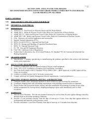
CJ5864-B<br />
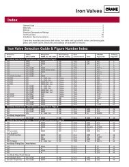
Figure 1. Bonnet Assembly for <strong>Design</strong> <strong>461</strong> <strong>Valve</strong> <strong>Body</strong><br />
-11-
Destgn <strong>461</strong><br />
Key 10 <strong>Valve</strong> Stem, 316 stainless steel<br />
BODY PORT CLASS<br />
SIZE, DIA.<br />
IN. In. mm. 600 900 & 1500 2500<br />
For Use With Standard Bonnet<br />
2 x 3l Std. Std. lOA X012 1069265 X862 . lOA X692<br />
3 x 4l Std. Std. . . . 1069265 X832 lOA X602<br />
4 x 62 2 to 3 51 to 76 a. . llA3429 x012 . . .<br />
4 x 63 2 to 3 51 to 76 . . . llA3429 X082 . . .<br />
6 x 82 3-l/2 to 89 to 114 llA3429 Xl62 llA3429 x112 . . .<br />
4-l/2<br />
6 x 83 3 to 4-l/2 76 to 114 llA3429 Xl22 llA3429 Xl32 . . .<br />
2 x 3l<br />
4 x 62<br />
4 x 63<br />
i6 x 82<br />
For Use With Radiation Bonnet<br />
HA3429 Xl42 HA3429 Xl52<br />
1183429 X112<br />
3 to 4-l/2 76 to 114 HA3429 Xl22 llA3429 Xl32 . . .<br />
1. For use with Group 1 actuators.<br />
2. For use with Group 100 actuators.<br />
3. For use with Group 101 actuators.<br />
Key 14 Standard Bonnet without equalizing connection<br />
STRMSIZR<br />
In. mm<br />
314 19.1<br />
1 25.4<br />
BODY BODY CLASS<br />
MATERIAL SIZE 300 or 600 1900 or 1500 1 2500<br />
WCB steel<br />
-1<br />
WCB steel<br />
2x3 2F8952 22012 2F6994 22012 lF8886 22012<br />
3x4 . . . 3F7897 22012 3F7818 XOOft2<br />
4x6 . . . 32Ao597 x012 . . .<br />
2x3 ..* 3B2408 22012 OX0912 22012<br />
3x4 . . . 2U8146 XOOA2 3D6819 22012<br />
.4 x 6 ..* 3B1592 22012 . . .<br />
-12-
Key 14 Radiation Fin Bonnet for 3/4 in. (19.1 mm) stem<br />
BODY CLASS<br />
SIZE, IN. 300 or 600 I 900 or 1500 2500<br />
2x3<br />
3x4<br />
4x6<br />
6x8<br />
2x3<br />
3x4<br />
4x6<br />
6x8<br />
WCB Steel <strong>Body</strong> Without Equalizing Cotiection<br />
<strong>Design</strong> <strong>461</strong> I<br />
3P1511 22012 3P1513 22012 3P1521 22012<br />
3F6997 XOOA2 2P1539 x0012 2P1535 X0012<br />
3P1515 22012 3P1537 x0012 . . .<br />
3P1541 x0012 . . . . . .<br />
WCB Steel <strong>Body</strong> With Equalizing Connection<br />
3P1512 XOOA2 3P1514 22012 3P1522 X0012<br />
3F6997 X0022 2P1540 X0032 2P1536 X0012<br />
3P1516 22012 3P1538 X0012 . . .<br />
3P1542 X0012 . . . . . .<br />
C5 Steel <strong>Body</strong> Without Equalizing Connection<br />
3P1515 29022 3P1537 x0022<br />
3P1512 X0012 3P1514 29022 3P1522 X0022<br />
3P1516 29022 3P1538 X0022 . . .<br />
3P1542 X0022 . . . . . .<br />
-13-
I <strong>Design</strong> <strong>461</strong><br />
I<br />
Key 14 Radiation Fin Bonnet for 1 in. (25.4 mm) stem<br />
BODY<br />
SIZE, IN. 300 or 600<br />
CLASS<br />
900 or 1500<br />
I<br />
WCB Steel <strong>Body</strong> Without Equalizing Connection<br />
2500<br />
2x3 3E6696 X0012 3D4085 22012 336695 X0012<br />
3x4 336705 22012 3c4534 22012 3LlO53 x0012<br />
4x6 336694 X0012 3E6692 X0012 . . .<br />
6x8 3E6704 X0012 3V8431 X0012 . . .<br />
2x3<br />
3x4<br />
4x6<br />
6x8<br />
2x3<br />
3x4<br />
4x6<br />
6x8<br />
WCB Steel <strong>Body</strong> With Equalizing Connection<br />
3E6696 X0032 3134085 X0012- 336695 X0032<br />
3E6705 X0022 3c4534 x0022 3L1053 X0032<br />
3E6694 X0032 3E6692 X0032 . . .<br />
3E6704 X0012 3V8431 X0032 . . .<br />
C5 Steel <strong>Body</strong> Without Equalizing Connection<br />
3E6696 X0022 3134085 29022 3E6695 X0022<br />
3E6705 X0012 3c4534 x0012 3L1053 x0022<br />
3E6694 X0022 3E6692 X0022 . . .<br />
336704 X0022 3V8431 X0022 . . .<br />
C5 Steel <strong>Body</strong> With Equalizing Connection<br />
2x3 3E6696 X0042 3D4085 X0022 3E6695 X0042<br />
3x4 3E6705 X0032 3C4534 X0032 3LlO53 X0042<br />
4x6 3E6694 X0042 3E6692 X0042 . . .<br />
6x8 3E6704 X0042 3V8431 X0042 . . *<br />
-14-
.<br />
<strong>Design</strong> <strong>461</strong><br />
Key 31 Pipe Plug, Lubricator, or Lubricator/Isolating <strong>Valve</strong> for use<br />
with both 3/4-inch (19.1 mn) and l-inch (25.4 mn) stems<br />
Part<br />
Pipe Plug<br />
Lubricator<br />
Lubr/ISO <strong>Valve</strong><br />
Bonnet Material<br />
WCB steel<br />
Cast chrome moly-steel<br />
All materials<br />
Actuator Groups (by Type Number)<br />
Carbon, chrome moly,<br />
carbon-moly<br />
Group 1<br />
2-l/8 in. (54 mm), 2-13/16 in. (71 mm),<br />
or 3-9/16 in. (90 mm) Yoke Boss<br />
350 - 2-13/16 in. (71.4 mm) Yoke Boss<br />
422 & 424<br />
470 Series - 2 in. (50.8 nnn) travel<br />
472 & 473<br />
512 & 512R<br />
513 & 513R<br />
603 Sr 1B<br />
608 84 618<br />
610 & 688<br />
611<br />
612 & 612R<br />
613 & 613R<br />
644 & 645<br />
655<br />
657 & 667 - 3 in. (76.2 mm) travel<br />
1008 - 2-13/16 in. (71.4 mm) Yoke Boss<br />
-15-<br />
Part Number<br />
llA7675 24662<br />
. llA7675 35072<br />
KMFXl-F9<br />
KMKKl-FlO<br />
Group 100<br />
5 in. (127 mm) Yoke Boss<br />
350<br />
470<br />
471<br />
472<br />
473<br />
474<br />
475<br />
476<br />
657<br />
1008<br />
Group 101<br />
5 in. (127 mm) Yoke Boss<br />
667
AFJ506<br />
<strong>Design</strong> <strong>461</strong><br />
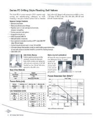
Figure 2. <strong>Design</strong> <strong>461</strong> <strong>Valve</strong> <strong>Body</strong> Assembly<br />
(RSHRI”) Fisher Controls<br />
For intomtatlon write:<br />
P.O. Box 190, Marshmown. low8 50158. USA.<br />
or Brenchlay House. Maidstone. Ken1 ME 14 1UQ. England
![ratings & DEFINITIONS452-467_Technical Information[1].pdf](https://img.yumpu.com/49871719/1/190x245/ratings-definitions452-467-technical-information1pdf.jpg?quality=85)