TRIDENT MODEL PD765 Instruction Manual
TRIDENT MODEL PD765 Instruction Manual
TRIDENT MODEL PD765 Instruction Manual

Create successful ePaper yourself
Turn your PDF publications into a flip-book with our unique Google optimized e-Paper software.
<strong>TRIDENT</strong> <strong>MODEL</strong> <strong>PD765</strong><br />
<strong>Instruction</strong> <strong>Manual</strong><br />
• Accepts Current, Voltage, TC, & RTD Inputs<br />
• 4 Digit Display, 0.56" (14 mm) High, Red LEDs<br />
• Linear or Square Root with Low-Flow Cutoff<br />
• Maximum/Minimum Display<br />
• Type 4X, NEMA 4X, IP65 Front<br />
Sunlight<br />
• Universal Power Supply 85-265 VAC Readable<br />
• 12-36 VDC/12-24 VAC Power Option Display!<br />
• Two Relays or 4-20 mA Output Option<br />
• 24 VDC Transmitter Power Supply Options<br />
• Serial Communication Adapters<br />
RS-232 & RS-422/485 Options<br />
• Modbus ® RTU Option<br />
• Copy Meter Settings to Other Meters<br />
• MeterView ® Software - Configuration & Data Acquisition<br />
PRECISION DIGITAL CORPORATION<br />
19 Strathmore Road • Natick MA 01760 USA<br />
Tel (800) 343-1001 • Fax (508) 655-8990<br />
www.predig.com
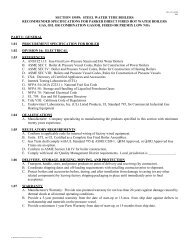
Trident Model <strong>PD765</strong> Universal Input Meter<br />
<strong>Instruction</strong> <strong>Manual</strong><br />
Disclaimer<br />
The information contained in this document is subject to change<br />
without notice. Precision Digital makes no representations or warranties<br />
with respect to the contents hereof, and specifically disclaims<br />
any implied warranties of merchantability or fitness for a particular<br />
purpose.<br />
Registered Trademarks<br />
MeterView ® is a registered trademark of Precision Digital Corporation,<br />
Modbus ® is a registered trademark of Schneider Automation Inc. All<br />
other trademarks mentioned in this document are the property of their<br />
respective owners.<br />
© 2005 Precision Digital Corporation. All rights reserved.<br />
Visit our Web Site<br />
http://www.predig.com<br />
For an Interactive VirtualMeter Demo!<br />
2
Trident Model <strong>PD765</strong> Universal Input Meter<br />
INTRODUCTION<br />
3<br />
<strong>Instruction</strong> <strong>Manual</strong><br />
The Trident is a multipurpose, easy to use digital meter. It accepts current,<br />
voltage, thermocouple, and RTD signals. The four front panel buttons<br />
make the setup and programming an easy task.<br />
The isolated 24 VDC transmitter power (optional) can be used to power<br />
the input transmitter, the 4-20 mA output, or other devices.<br />
The two relays (optional) can be used for alarm indication or process control<br />
applications, such as pump alternation control.<br />
The 4-20 mA isolated output and the Modbus RTU serial communication<br />
options make the Trident an excellent addition to any system.<br />
ORDERING INFORMATION<br />
85-265 VAC*<br />
Model<br />
12-36 VDC*<br />
Model<br />
Options Installed<br />
<strong>PD765</strong>-6R0-00 <strong>PD765</strong>-7R0-00 No options<br />
<strong>PD765</strong>-6R0-10<br />
<strong>PD765</strong>-6R2-00 <strong>PD765</strong>-7R2-00 2 relays<br />
<strong>PD765</strong>-6R2-10<br />
24 V transmitter supply<br />
<strong>PD765</strong>-6R3-00 <strong>PD765</strong>-7R3-00 4-20 mA output<br />
<strong>PD765</strong>-6R3-10<br />
<strong>PD765</strong>-6R3-20<br />
2 relays & 24 V transmitter supply<br />
4-20 mA output & 24 V supply<br />
4-20 mA output & dual 24 V supplies<br />
To request meters with Modbus option enabled, replace the last digit with a “1”.<br />
Modbus option may be ordered separately by requesting P/N: PDN-MODBUS<br />
*All models may be powered from AC or DC, see Specifications for details.<br />
Accessories<br />
Model Description<br />
PDA7232 RS-232 serial adapter with PDA7420 included<br />
PDA7420 Trident meter copy cable, 7' (2.1 m)<br />
PDA7422 RS-422/485 serial adapter with PDA7420 included<br />
PDA7485-I RS-232 to RS-485 isolated converter<br />
PDA7485-N RS-232 to RS-485 non-isolated converter<br />
PDA7488 Trident RS-232/485 isolated multi-input adapter board<br />
PDA8485-I USB to RS-422/485 isolated converter<br />
PDA8485-N USB to RS-422/485 non-isolated converter<br />
PDA7503-X MeterView ® software (Note: X = 1, 2, or 3)<br />
Enclosures<br />
NEMA 4 & explosion-proof enclosures – See Web site.<br />
Plastic, steel, stainless steel & cast aluminum
Trident Model <strong>PD765</strong> Universal Input Meter<br />
Table of Contents<br />
<strong>Instruction</strong> <strong>Manual</strong><br />
INTRODUCTION ------------------------------------------------------------ 3<br />
ORDERING INFORMATION --------------------------------------------- 3<br />
SPECIFICATIONS---------------------------------------------------------- 7<br />
General-------------------------------------------------------------------------------7<br />
Process Input ----------------------------------------------------------------------8<br />
Temperature Inputs--------------------------------------------------------------9<br />
Relays Option-------------------------------------------------------------------- 10<br />
Isolated 4-20 mA Transmitter Output ------------------------------------ 11<br />
Serial Communications------------------------------------------------------- 11<br />
COMPLIANCE INFORMATION ----------------------------------------12<br />
Safety ------------------------------------------------------------------------------- 12<br />
Electromagnetic Compatibility--------------------------------------------- 12<br />
SAFETY INFORMATION ------------------------------------------------13<br />
INSTALLATION ------------------------------------------------------------14<br />
Unpacking------------------------------------------------------------------------- 14<br />
Panel Mounting------------------------------------------------------------------ 14<br />
Connections---------------------------------------------------------------------- 15<br />
Connector Labeling ---------------------------------------------------------- 15<br />
Power Connections ---------------------------------------------------------- 15<br />
Signal Connections ---------------------------------------------------------- 16<br />
Serial Communication ------------------------------------------------------- 19<br />
Relays and 24 V Output Connections ----------------------------------- 19<br />
Switching Inductive Loads-------------------------------------------------- 20<br />
4-20 mA Output & Input Signal Connections -------------------------- 21<br />
SETUP AND PROGRAMMING ----------------------------------------22<br />
Front Panel Buttons and Status LED Indicators --------------------- 23<br />
Display Functions and Messages----------------------------------------- 24<br />
Main Menu ------------------------------------------------------------------------ 27<br />
Setting Numeric Values ------------------------------------------------------ 28<br />
Setting Up the Meter (setu) ------------------------------------------------- 29<br />
Setting the Input Signal (inpt)-------------------------------------------- 30<br />
Setting the Decimal Point (dc.pt) ----------------------------------------- 31<br />
Setting the Temperature Scale (F C) ---------------------------------- 31<br />
Setting the Relay Operation (rely) -------------------------------------- 32<br />
4
Trident Model <strong>PD765</strong> Universal Input Meter <strong>Instruction</strong> <strong>Manual</strong><br />
Relay and Alarm Operation ------------------------------------------------ 35<br />
Scaling the 4-20 mA Analog Output (Aout)---------------------------- 41<br />
Program the Sensor Break Output Value (SEbr) --------------------- 42<br />
Analog Output when Display is Out of Range------------------------- 42<br />
Programming the Meter (prog)--------------------------------------------- 43<br />
Scaling the Meter (scal)---------------------------------------------------- 44<br />
Calibrating the Meter (Cal)------------------------------------------------- 46<br />
Recalibrating Temperature Inputs (Cal) -------------------------------- 46<br />
Recalibrating Process Inputs (ICal)------------------------------------- 47<br />
Setting Up the Password (pass) ------------------------------------------- 48<br />
Locking the Meter ------------------------------------------------------------ 48<br />
Unlocking the Meter---------------------------------------------------------- 48<br />
Advanced Features Menu---------------------------------------------------- 50<br />
Advanced Features Menu & Display Messages ---------------------- 51<br />
Offset Adjustment (Adj)----------------------------------------------------- 53<br />
Noise Filter (fltr)------------------------------------------------------------ 53<br />
Noise Filter Bypass (byps) ------------------------------------------------- 54<br />
Serial Communications (serl) -------------------------------------------- 54<br />
Select Menu (SElc) ---------------------------------------------------------- 55<br />
Linear or Square Root Function (linr or Sqrt) ---------------------- 55<br />
Low-Flow Cutoff (cutF) ----------------------------------------------------- 56<br />
Display Intensity (inty) ----------------------------------------------------- 56<br />
Meter Copy Function (Copy) ----------------------------------------------- 57<br />
Internal Calibration (ICal)-------------------------------------------------- 59<br />
OPERATION ----------------------------------------------------------------62<br />
Front Panel Buttons Operation -------------------------------------------- 62<br />
Maximum/Minimum Readings---------------------------------------------- 63<br />
MOUNTING DIMENSIONS ----------------------------------------------64<br />
TROUBLESHOOTING----------------------------------------------------65<br />
Diagnostics Menu (diag)----------------------------------------------------- 65<br />
Determining Software Version -------------------------------------------- 65<br />
Reset Meter to Factory Defaults ------------------------------------------- 66<br />
Factory Defaults & User Settings----------------------------------------- 67<br />
Troubleshooting Tips --------------------------------------------------------- 69<br />
QUICK USER INTERFACE REFERENCE GUIDE----------------70<br />
5
Trident Model <strong>PD765</strong> Universal Input Meter<br />
<strong>Instruction</strong> <strong>Manual</strong><br />
Table of Figures<br />
Figure 1. Panel Cutout and Mounting...............................................14<br />
Figure 2. Connector Labeling for Two Relays & 24 V Supply.........15<br />
Figure 3. Power Connections ............................................................15<br />
Figure 4. Transmitter Powered by Ext. Supply or Self-Powered ....16<br />
Figure 5. Transmitters Powered by Internal Supply (Optional) ......16<br />
Figure 6. Voltage Input Connections ................................................17<br />
Figure 7. Thermocouple Input Connections ....................................17<br />
Figure 8. Three-Wire RTD Input Connections ..................................18<br />
Figure 9. Two-Wire RTD Input Connections.....................................18<br />
Figure 10. Four-Wire RTD Input Connections..................................19<br />
Figure 11. Relay & 24 V Output Connections...................................19<br />
Figure 12. AC and DC Loads Protection...........................................20<br />
Figure 13. Low Voltage DC Loads Protection ..................................20<br />
Figure 14. 4-20 mA Output & Input Signal Powered by Meter ........21<br />
Figure 15. 4-20 mA Output Powered Externally...............................21<br />
Figure 16. Meter Copy Connection ...................................................57<br />
Figure 17. Meter Dimensions – Side View ........................................64<br />
Figure 18. Case Dimensions - Top View...........................................64<br />
6
Trident Model <strong>PD765</strong> Universal Input Meter<br />
SPECIFICATIONS<br />
7<br />
<strong>Instruction</strong> <strong>Manual</strong><br />
Except where noted all specifications apply to operation at +25°C.<br />
General<br />
DISPLAY<br />
0.56" (14 mm) high, red LED<br />
Four digits (-1999 to 9999), automatic lead zero blanking.<br />
DISPLAY INTENSITY Eight intensity levels<br />
DISPLAY<br />
UPDATE RATE<br />
Process/RTD: 3.7-5/second<br />
Thermocouple: 1.8-2.5/second<br />
OVERRANGE Display flashes 9999<br />
UNDERRANGE Display flashes -1999<br />
PROGRAMMING<br />
METHODS<br />
NOISE FILTER<br />
RECALIBRATION<br />
MAX/MIN<br />
DISPLAY<br />
PASSWORD<br />
NON-VOLATILE<br />
MEMORY<br />
POWER<br />
OPTIONS<br />
FUSE<br />
ISOLATED<br />
TRANSMITTER<br />
POWER SUPPLY<br />
NORMAL MODE<br />
REJECTION<br />
ISOLATION<br />
OVERVOLTAGE<br />
CATEGORY<br />
Four front panel buttons, PC and MeterView ® software, or<br />
cloning using Copy function<br />
Programmable from 2 to 199 (0 will disable filter)<br />
All ranges are calibrated at the factory. Recalibration is<br />
recommended at least every 12 months.<br />
Max/min readings reached by the process are stored until<br />
reset by the user or until power to the meter is turned off.<br />
Programmable password restricts modification of<br />
programmed settings.<br />
All programmed settings are stored in non-volatile memory<br />
for a minimum of ten years if power is lost.<br />
85-265 VAC, 50/60 Hz<br />
Model<br />
Watts<br />
90-265 VDC, 20 W max<br />
<strong>PD765</strong>-6RX-0* 8<br />
or 12-36 VDC, 12-24 VAC, 6 W max<br />
<strong>PD765</strong>-6RX-1, 2* 20<br />
See table for power consumption<br />
(*X: number depends on option) <strong>PD765</strong>-7RX-0* 6<br />
Required fuse: UL Recognized, 5 A max, slow blow<br />
Up to 6 meters may share one 5 A fuse<br />
One or two transmitter power supplies (Optional)<br />
P or P1: 24 VDC ± 10% @ 200 mA max. (-1 option)<br />
P1 & P2: 24 VDC ± 10% @ 200 mA & 40 mA max. (-2 option)<br />
64 dB at 50/60 Hz<br />
4 kV input/output-to-power line<br />
500 V input-to-output or output-to-P1/P2 supplies<br />
Installation Overvoltage Category II:<br />
Local level with smaller transient overvoltages than Installation<br />
Overvoltage Category III.
Trident Model <strong>PD765</strong> Universal Input Meter<br />
ENVIRONMENTAL Operating temperature range: 0 to 65°C<br />
Storage temperature range: -40 to 85°C<br />
Relative humidity: 0 to 90% non-condensing<br />
CONNECTIONS<br />
ENCLOSURE<br />
MOUNTING<br />
TIGHTENING<br />
TORQUE<br />
OVERALL<br />
DIMENSIONS<br />
WEIGHT<br />
WARRANTY<br />
EXTENDED<br />
WARRANTY<br />
Process Input<br />
INPUTS<br />
ACCURACY<br />
FUNCTION<br />
LOW-FLOW<br />
CUTOFF<br />
TEMPERATURE<br />
DRIFT<br />
DECIMAL POINT<br />
CALIBRATION<br />
RANGE<br />
INPUT<br />
IMPEDANCE<br />
INPUT<br />
OVERLOAD<br />
<strong>Instruction</strong> <strong>Manual</strong><br />
Removable screw terminal blocks accept 12 to 22 AWG<br />
wire, RJ11 for serial communication adapters<br />
1/8 DIN, high impact plastic, UL 94V-0, color: gray<br />
1/8 DIN panel cutout required. Two panel mounting<br />
bracket assemblies provided<br />
Screw terminal connectors: 4.5 lb-in (0.5 Nm)<br />
2.45" x 4.68" x 4.19" (62 mm x 119 mm x 106 mm)<br />
(H x W x D)<br />
9.5 oz (269 g) (including options)<br />
3 years parts & labor<br />
1 or 2 years, refer to the Price List for details.<br />
Field selectable:<br />
±20 mADC (0-20, 4-20 mA) and ±10 VDC (0-5, 1-5, 0-10 V)<br />
±0.05% of span ±1 count, square root: 10-100% FS<br />
Linear or square root<br />
0-9999 (0 disables cutoff function)<br />
50 PPM/°C from 0 to 65°C ambient<br />
Up to three decimal places for process inputs:<br />
d.ddd, dd.dd, ddd.d, or dddd<br />
An Error message will appear if input 1 and input 2 signals<br />
are too close together.<br />
Input<br />
Range<br />
4-20 mA 0.40 mA<br />
±10 V 0.20 V<br />
Minimum Span<br />
Input 1 & Input 2<br />
Voltage ranges: greater than 1 MΩ<br />
Current ranges: 50 - 100 Ω (depending on resettable fuse impedance)<br />
Current input protected by resettable fuse.<br />
Fuse resets automatically after fault is removed.<br />
8
Trident Model <strong>PD765</strong> Universal Input Meter<br />
Temperature Inputs<br />
<strong>Instruction</strong> <strong>Manual</strong><br />
INPUTS<br />
RESOLUTION<br />
ACCURACY<br />
Field selectable: type J, K, T, or E thermocouples;<br />
100 Ω platinum RTD (0.00385 or 0.00392 curve)<br />
1° for all thermocouples and RTD inputs<br />
1° or 0.1° for Type T thermocouple<br />
Input Type Range Accuracy<br />
Type J<br />
Type K<br />
Type T<br />
Type T<br />
0.1° Res<br />
Type E<br />
-58° to 1382° F<br />
-50° to 750°C<br />
-58° to 2300° F<br />
-50° to 1260°C<br />
-292° to 700° F<br />
-180° to 371°C<br />
-199.9° to 700.0° F<br />
-180.0° to 371.0°C<br />
-58° to 1578° F<br />
-50° to 870°C<br />
100 Ω RTD -328° to 1382°F<br />
-200° to 750°C<br />
COLD<br />
JUNCTION<br />
REFERENCE<br />
TEMPERATURE<br />
DRIFT<br />
OFFSET<br />
ADJUSTMENT<br />
INPUT<br />
IMPEDANCE<br />
SENSOR BREAK<br />
DETECTION<br />
±2°F<br />
±1°C<br />
±2°F<br />
±1°C<br />
±2°F<br />
±1°C<br />
±1.8°F<br />
±1.0°C<br />
±2°F<br />
±1°C<br />
±1°F<br />
±1°C<br />
Automatic, fixed, no user calibration needed<br />
±2°C maximum<br />
0 to 65°C ambient temperature<br />
Programmable to ±19.9°. This parameter allows the user to<br />
apply an offset value to the temperature being displayed.<br />
Greater than 100 kΩ<br />
Open TC or RTD sensor indicated by display flashing oPEn.<br />
All relays and alarm status LEDs go to alarm state.<br />
Analog output goes to the programmed sensor break value.<br />
9
Trident Model <strong>PD765</strong> Universal Input Meter<br />
Relays Option<br />
<strong>Instruction</strong> <strong>Manual</strong><br />
RATING<br />
ELECTRICAL<br />
NOISE<br />
SUPPRESSION<br />
DEADBAND<br />
HIGH OR LOW<br />
ALARM<br />
RELAY<br />
OPERATION<br />
RELAY RESET<br />
TIME DELAY<br />
FAIL-SAFE<br />
OPERATION<br />
AUTO<br />
INITIALIZATION<br />
2 SPDT (Form C); rated 3 A @ 30 VDC or 3 A @ 250 VAC<br />
resistive load; 1/14 HP @ 125/250 VAC for inductive loads<br />
A suppressor (snubber) should be connected to each relay<br />
contact switching inductive loads to prevent<br />
disruption to the microprocessor’s operation.<br />
Recommended suppressor value: 0.01 µF/470 Ω, 250 VAC<br />
(PDX6901).<br />
0-100% of full scale, user selectable<br />
User may program any alarm for high or low trip point.<br />
Automatic (non-latching)<br />
Latching<br />
Pump alternation control<br />
User selectable via front panel buttons or PC<br />
Automatic reset only (non-latching)<br />
Automatic + manual reset at any time (non-latching)<br />
<strong>Manual</strong> reset only, at any time (latching)<br />
<strong>Manual</strong> reset only after alarm condition has cleared (latching)<br />
Automatic reset: Relays will automatically reset when the<br />
input passes the reset point.<br />
<strong>Manual</strong> reset: Front panel ACK button. Pressing ACK resets<br />
all manually resettable relays.<br />
0 to 199 seconds, on and off delays<br />
Programmable and independent for each relay<br />
Programmable<br />
Independent for each relay<br />
When power is applied to the meter, relays will reflect the<br />
state of the input to the meter.<br />
Fail-safe operation: relay coil is energized in non-alarm condition. In<br />
case of power failure, relay will go to alarm state.<br />
10
Trident Model <strong>PD765</strong> Universal Input Meter<br />
Isolated 4-20 mA Transmitter Output<br />
<strong>Instruction</strong> <strong>Manual</strong><br />
OUTPUT RANGE 1.00 to 23.00 mA typical<br />
CALIBRATION<br />
Factory calibrated for 4-20 mA<br />
SCALING RANGE 0.00 to 23.99 mA for any display range,<br />
see output range above<br />
ACCURACY ± 0.1% FS ± 0.004 mA<br />
TEMPERATURE<br />
DRIFT<br />
ISOLATED<br />
TRANSMITTER<br />
POWER SUPPLY<br />
EXTERNAL LOOP<br />
POWER SUPPLY<br />
OUTPUT LOOP<br />
RESISTANCE<br />
50 PPM/°C from 0 to 65°C ambient<br />
Note: Analog output drift is separate from input drift.<br />
One or two transmitter power supplies (Optional)<br />
P1: 24 VDC ± 10% @ 200 mA max. (-1 option)<br />
P1 & P2: 24 VDC ± 10% @ 200 mA & 40 mA max. (-2 option)<br />
35 VDC maximum<br />
Power supply Minimum Maximum<br />
24 VDC 10 Ω 700 Ω<br />
35 VDC (external) 100 Ω 1200 Ω<br />
Serial Communications<br />
METER<br />
ADDRESS<br />
BAUD RATE<br />
TRANSMIT<br />
TIME DELAY<br />
DATA<br />
PARITY<br />
BYTE-TO-BYTE<br />
TIMEOUT<br />
TURN AROUND<br />
DELAY<br />
PDC protocol: 0 - 99<br />
Modbus protocol: 1 - 247<br />
300 – 19,200 bps<br />
Programmable between 0 and 199 ms<br />
or transmitter always on for RS422 communication<br />
8 bit (1 start bit, 1 stop bit)<br />
None, even, or odd<br />
(Modbus only; PDC protocol does not use parity)<br />
0.01 – 2.54 sec (Modbus only)<br />
Less than 2 ms (fixed)<br />
Refer to PDC and Modbus Serial Communication Protocol manuals for details.<br />
11
Trident Model <strong>PD765</strong> Universal Input Meter<br />
COMPLIANCE INFORMATION<br />
Safety<br />
UL LISTED<br />
UL FILE NUMBER<br />
FRONT PANEL<br />
LOW VOLTAGE<br />
DIRECTIVE<br />
USA and Canada<br />
UL 508 Industrial Control Equipment<br />
E160849<br />
<strong>Instruction</strong> <strong>Manual</strong><br />
UL Type 4X, NEMA 4X, IP65; panel gasket provided<br />
EN 61010-1:2001 (UL 61010C-1)<br />
Safety requirements for measurement, control, and<br />
laboratory use<br />
Electromagnetic Compatibility<br />
EMISSIONS EN 55011:1998<br />
Group 1 Class A ISM emissions requirements<br />
Radiated<br />
Class A<br />
Emissions<br />
AC Mains<br />
Class A<br />
Conducted<br />
Emissions<br />
IMMUNITY EN 61000-6-2:2001<br />
EMC heavy industrial generic immunity standard<br />
RFI - Amplitude 80 -1000 MHz 10 V/m 80% AM (1 kHz)<br />
Modulated<br />
Electrical Fast ±2kV AC mains, ±1kV other<br />
Transients<br />
Electrostatic ±4kV contact, ±8kV air<br />
Discharge<br />
RFI - Conducted 10V, 0.15-80 MHz, 1kHz 80% AM<br />
AC Surge<br />
±2kV Common, ±1kV Differential<br />
Surge<br />
1KV (CM)<br />
Power-Frequency 3 A/m 70%V for 0.5 period<br />
Magnetic Field<br />
Voltage Dips 40%V for 5 & 50 periods<br />
Voltage<br />
Trident Model <strong>PD765</strong> Universal Input Meter<br />
<strong>Instruction</strong> <strong>Manual</strong><br />
Note:<br />
Testing was conducted on Trident Meters installed through the covers<br />
of grounded metal enclosures with cable shields grounded at the<br />
point of entry representing installations designed to optimize EMC<br />
performance.<br />
Declaration of Conformity available at www.predig.com<br />
SAFETY INFORMATION<br />
!<br />
CAUTION: Read complete<br />
instructions prior to installation<br />
and operation of the<br />
meter.<br />
WARNING: Risk of<br />
electric shock.<br />
WARNING<br />
Hazardous voltages exist within enclosure. Installation and service<br />
should be performed only by trained service personnel.<br />
13
Trident Model <strong>PD765</strong> Universal Input Meter<br />
INSTALLATION<br />
Unpacking<br />
<strong>Instruction</strong> <strong>Manual</strong><br />
There is no need to remove the meter from its case to complete<br />
the installation, wiring, and setup of the meter.<br />
Remove the meter from box. Inspect the packaging and contents<br />
for damage. Report damages, if any, to the carrier.<br />
If any part is missing or the meter malfunctions, please contact<br />
your supplier or the factory for assistance.<br />
Panel Mounting<br />
• Prepare a standard 1/8 DIN panel cutout – 3.622" x 1.772" (92 mm<br />
x 45 mm). Refer to Mounting Dimensions, page 64 for more details.<br />
• Clearance: allow at least 4" (102 mm) behind the panel for wiring.<br />
• Panel thickness: 0.04" - 0.25" (1.0 mm - 6.4 mm).<br />
Recommended minimum panel thickness to maintain Type 4X<br />
rating: 0.06" (1.5 mm) steel panel, 0.16" (4.1 mm) plastic panel.<br />
• Remove the two mounting brackets provided with the meter (back-off<br />
the two screws so that there is ¼" (6.4 mm) or less through the<br />
bracket. Slide the bracket toward the front of the case and remove).<br />
• Insert meter into the panel cutout.<br />
• Install mounting brackets and tighten the screws against the panel.<br />
To achieve a proper seal, tighten the mounting bracket screws<br />
evenly until meter is snug to the panel along its short side. DO NOT<br />
OVER TIGHTEN, as the rear of the panel may be damaged.<br />
A<br />
3.622" (92mm)<br />
Gasket<br />
Panel<br />
Removable<br />
Connectors<br />
1.772"<br />
B<br />
(45mm)<br />
Square Corners to 0.060"<br />
(1.5mm) Max Radius<br />
Panel Cutout<br />
to DIN 43700<br />
Tolerances:<br />
A: +0.032 (+0.8mm)<br />
-0.000 (-0.0mm)<br />
B: +0.024 (+0.6mm)<br />
-0.000 (-0.0mm)<br />
Mounting<br />
Bracket<br />
Figure 1. Panel Cutout and Mounting<br />
14<br />
Mounting<br />
Screw
Trident Model <strong>PD765</strong> Universal Input Meter<br />
Connections<br />
<strong>Instruction</strong> <strong>Manual</strong><br />
All connections are made to removable screw terminal connectors<br />
located at the rear of the meter.<br />
!<br />
Use copper wire with 60°C or 60/75°C insulation<br />
for all line voltage connections. Observe all safety<br />
regulations. Electrical wiring should be performed<br />
in accordance with all applicable national, state,<br />
and local codes to prevent damage to the meter<br />
and ensure personnel safety.<br />
Connector Labeling<br />
The connectors label, affixed to the meter, shows the location of all connectors<br />
available with requested configuration. It also identifies the location<br />
of the RTD/TC selector switch.<br />
RELAY2<br />
RELAY1<br />
4 3<br />
6 5 2 1<br />
24V OUT<br />
2 1<br />
POWER<br />
2 1<br />
NO NC COM NO NC COM<br />
RTD<br />
TC<br />
P+ P-<br />
+ -<br />
V+ mA+ EXC T+ COM<br />
3 4<br />
1 2 5<br />
RTD<br />
TC<br />
1 2 3 4 5 6<br />
SWITC H<br />
EL1601<br />
Figure 2. Connector Labeling for Two Relays & 24 V Supply<br />
Power Connections<br />
Power connections are made to a two-terminal connector labeled<br />
POWER on Figure 2. The meter will operate regardless of DC polarity<br />
connection. The + and - symbols are only a suggested wiring convention.<br />
POWER CONNECTOR<br />
2<br />
1<br />
+ -<br />
Required External Fuse:<br />
5 A max, Slow Blow<br />
AC or DC<br />
POWER<br />
Figure 3. Power Connections<br />
15
Trident Model <strong>PD765</strong> Universal Input Meter<br />
Signal Connections<br />
<strong>Instruction</strong> <strong>Manual</strong><br />
Signal connections are made to a five-terminal connector labeled<br />
SIGNAL on Figure 2. The COM (common) terminal is the return for all<br />
types of input signals.<br />
Current and Voltage Connections<br />
The following figures show examples for current and voltage connections.<br />
There are no switches or jumpers to set up for current and voltage inputs.<br />
Setup and programming is performed through the front panel buttons.<br />
SIGNAL CONNECTOR<br />
V+ mA+ EXC T+ COM<br />
1 2<br />
3 4<br />
5<br />
SIGNAL CONNECTOR<br />
V+ mA+ EXC T+ COM<br />
1 2<br />
3 4<br />
5<br />
- + + -<br />
2-Wire<br />
4-20 mA<br />
Transmitter<br />
External<br />
Power<br />
Supply<br />
+ -<br />
2-Wire 4-20 mA<br />
Self-Powered<br />
Transmitter<br />
Figure 4. Transmitter Powered by Ext. Supply or Self-Powered<br />
SIGNAL CONNECTOR<br />
V+ mA+ EXC T+ COM<br />
24V OUT<br />
P+ P-<br />
SIGNAL CONNECTOR<br />
V+ mA+ EXC T+ COM<br />
24V OUT<br />
P+ P-<br />
1 2<br />
3 4<br />
5<br />
2 1<br />
1 2<br />
3 4<br />
5<br />
2 1<br />
- +<br />
2-Wire<br />
4-20 mA<br />
Transmitter<br />
Signal - +<br />
3-Wire<br />
4-20 mA<br />
Transmitter<br />
Figure 5. Transmitters Powered by Internal Supply (Optional)<br />
The current input is protected against current overload by a resettable<br />
fuse. The display may or may not show a fault condition depending on<br />
the nature of the overload.<br />
The fuse limits the current to a safe level when it detects a fault condition,<br />
and automatically resets itself when the fault condition is removed.<br />
16
Trident Model <strong>PD765</strong> Universal Input Meter<br />
<strong>Instruction</strong> <strong>Manual</strong><br />
SIGNAL CONNECTOR<br />
V+ mA+ EXC T+ COM<br />
1 2<br />
3 4<br />
5<br />
SIGNAL CONNECTOR<br />
V+ mA+ EXC T+ COM<br />
1 2<br />
3 4<br />
5<br />
24V OUT<br />
P+ P-<br />
2 1<br />
+ -<br />
Voltage<br />
Signal<br />
Signal - +<br />
3-Wire<br />
Voltage<br />
Transducer<br />
Figure 6. Voltage Input Connections<br />
The meter is capable of accepting any voltage from -10 VDC to +10 VDC.<br />
Thermocouple and RTD Connections<br />
The following figures show examples for thermocouple and RTD connections.<br />
The RTD/TC selector switch must be set to the proper position for the<br />
meter to accept the selected temperature input.<br />
The input type is selected using the Setup menu.<br />
Selected thermocouple input must correspond to thermocouple sensor<br />
and wire type used.<br />
SIGNAL CONNECTOR<br />
V+ mA+ EXC T+ COM<br />
1 2<br />
3 4<br />
5<br />
1 2 3 4 5 6<br />
RTD<br />
TC<br />
+<br />
-<br />
Switch<br />
Position<br />
TC<br />
Figure 7. Thermocouple Input Connections<br />
17
Trident Model <strong>PD765</strong> Universal Input Meter<br />
SIGNAL<br />
CONNECTOR<br />
V+ mA+ EXC T+<br />
1 2<br />
3 4<br />
5<br />
COM<br />
<strong>Instruction</strong> <strong>Manual</strong><br />
1 2 3 4 5 6<br />
RTD<br />
TC<br />
RTD<br />
Sensor<br />
Switch<br />
Position<br />
Figure 8. Three-Wire RTD Input Connections<br />
The meter accepts two, three, or four-wire RTDs. The three-wire RTD<br />
connection has built-in lead wire compensation.<br />
SIGNAL<br />
CONNECTOR<br />
V+ mA+ EXC T+<br />
1 2<br />
3 4<br />
5<br />
COM<br />
1 2 3 4 5 6<br />
RTD<br />
TC<br />
RTD<br />
Sensor<br />
Switch<br />
Position<br />
Figure 9. Two-Wire RTD Input Connections<br />
Lead wire compensation for two-wire RTDs can be applied using the<br />
Adjust menu. See Offset Adjustment (Adj), page 53.<br />
18
Trident Model <strong>PD765</strong> Universal Input Meter<br />
<strong>Instruction</strong> <strong>Manual</strong><br />
SIGNAL CONNECTOR<br />
V+ mA+ EXC T+ COM<br />
1 2<br />
3 4<br />
5<br />
1 2 3 4 5 6<br />
RTD<br />
TC<br />
RTD<br />
Sensor<br />
Switch<br />
Position<br />
NC<br />
Figure 10. Four-Wire RTD Input Connections<br />
The four-wire RTD connection is similar to the three-wire. One of the<br />
leads of a four-wire RTD is not connected, and may be clipped off.<br />
The three-wire connection provides sufficient lead wire compensation to<br />
provide accurate readings even with long leads.<br />
Serial Communication<br />
Serial communication connection is made to an RJ11 connector labeled<br />
SERIAL on Figure 2. Use PDA7232 for RS-232 interfacing.<br />
Use PDA7422 for RS-422/485 interfacing.<br />
Use PDA7420 for meter-to-meter interfacing for cloning purposes (i.e.<br />
copying programmed settings from one meter to other meters).<br />
Relays and 24 V Output Connections<br />
Relay connections are made to a six-terminal connector labeled<br />
RELAY1, RELAY2 on Figure 2. The COM (common) terminals of the<br />
relays should not be confused with the COM (common) terminal of the<br />
SIGNAL connector. The 24 VDC output is available at the connector<br />
labeled 24V OUT, next to the relays connector.<br />
RELAY2<br />
RELAY1<br />
24V OUT<br />
6 5 4 3 2 1 2 1<br />
NO NC COM NO NC COM<br />
P+ P-<br />
Figure 11. Relay & 24 V Output Connections<br />
19
Trident Model <strong>PD765</strong> Universal Input Meter<br />
<strong>Instruction</strong> <strong>Manual</strong><br />
Switching Inductive Loads<br />
The use of suppressors (snubbers) is strongly recommended when switching<br />
inductive loads to prevent disrupting the microprocessor’s operation. The suppressors<br />
also prolong the life of the relay contacts. Suppression can be obtained<br />
with resistor-capacitor (RC) networks assembled by the user or purchased as<br />
complete assemblies. Refer to the following circuits for RC network assembly<br />
and installation:<br />
C<br />
R<br />
C<br />
R<br />
Figure 12. AC and DC Loads Protection<br />
Choose R and C as follows:<br />
R: 0.5 to 1 Ω for each volt across the contacts<br />
C: 0.5 to 1 µF for each amp through closed contacts<br />
Notes:<br />
1. Use capacitors rated for 250 VAC.<br />
2. RC networks may affect load release time of solenoid loads. Check to confirm<br />
proper operation.<br />
3. Install the RC network at the meter's relay screw terminals. An RC network<br />
may also be installed across the load. Experiment for best results.<br />
Use a diode with a reverse<br />
breakdown voltage two to<br />
three times the circuit voltage<br />
and forward current at<br />
least as large as the load<br />
current.<br />
Figure 13. Low Voltage DC Loads Protection<br />
RC Networks Available from Precision Digital<br />
RC networks are available from Precision Digital and should be applied to each<br />
relay contact switching an inductive load. Part number: PDX6901.<br />
20
Trident Model <strong>PD765</strong> Universal Input Meter<br />
4-20 mA Output & Input Signal Connections<br />
<strong>Instruction</strong> <strong>Manual</strong><br />
Connections for the 4-20 mA transmitter output are made to the connector<br />
terminals labeled “mA OUT, I-, I+”. The 4-20 mA output may be<br />
powered from an internal power supply (optional) or from an external<br />
power supply.<br />
SIGNAL CONNECTOR<br />
V+ mA+ EXC T+ COM<br />
1 2<br />
3 4<br />
5<br />
mA OUT<br />
I-<br />
6<br />
I+<br />
P1+<br />
24V OUT<br />
P2-<br />
P1-<br />
P2+<br />
5 4<br />
3 2<br />
1<br />
-<br />
2-Wire<br />
4-20 mA<br />
Transmitter<br />
+<br />
+ -<br />
Remote Display,<br />
Chart Recorder,<br />
etc.<br />
Figure 14. 4-20 mA Output & Input Signal Powered by Meter<br />
mA OUT<br />
I- I+<br />
6<br />
5<br />
External<br />
Power<br />
Supply<br />
- +<br />
+ -<br />
Remote Display,<br />
Chart Recorder,<br />
etc.<br />
Figure 15. 4-20 mA Output Powered Externally<br />
21
Trident Model <strong>PD765</strong> Universal Input Meter<br />
<strong>Instruction</strong> <strong>Manual</strong><br />
SETUP AND PROGRAMMING<br />
• There is no need to recalibrate the meter<br />
when first received from the factory.<br />
• The meter is factory calibrated prior to<br />
shipment, for all input types, in milliamps,<br />
volts, and degrees respectively. The calibration<br />
equipment is certified to NIST standards.<br />
Overview<br />
There are no jumpers involved in the setup process of the meter. The<br />
RTD/TC selector switch, located between the SIGNAL and SERIAL<br />
connectors, must be set accordingly for the meter to accept RTD or<br />
thermocouple inputs, Figure 2.<br />
Setup and programming is done through the front panel buttons.<br />
After power and signal connections have been completed and verified,<br />
apply power to the meter.<br />
For<br />
Quick User Interface Reference Guide<br />
go to page 70<br />
22
Trident Model <strong>PD765</strong> Universal Input Meter<br />
<strong>Instruction</strong> <strong>Manual</strong><br />
Front Panel Buttons and Status LED Indicators<br />
1<br />
9765<br />
2<br />
S<br />
R<br />
Button<br />
Symbol<br />
MENU RESET MAX<br />
ACK<br />
Description LED Status<br />
Menu 1 Alarm 1<br />
Right arrow/Reset 2 Alarm 2<br />
Up arrow/Max S Set point indicator<br />
Enter/Ack R Reset point indicator<br />
• Press the Menu button to enter or exit the Programming Mode at<br />
any time.<br />
• Press the Right arrow button to move to the next digit during digit<br />
programming.<br />
• Press the Up arrow button to scroll through the menus, decimal<br />
point, or to increment the value of a digit.<br />
• Press the Enter/Ack button to access a menu or to accept a setting.<br />
• Press and hold the Right arrow and the Menu buttons, for three<br />
seconds, to access the Advanced features of the meter (Press and<br />
hold Right arrow first then Menu).<br />
For Interactive VirtualMeter<br />
Demo visit<br />
www.predig.com<br />
23
Trident Model <strong>PD765</strong> Universal Input Meter<br />
<strong>Instruction</strong> <strong>Manual</strong><br />
Display Functions and Messages<br />
The meter displays various functions and messages during<br />
setup/programming and operation. The following table shows the displayed<br />
functions and messages with their action/setting description.<br />
Display Parameter Action/Setting<br />
setu Setup Enter Setup menu<br />
inpt Input Enter Input menu<br />
4-20 4-20 mA Set meter for 4-20 mA input<br />
0-10 0-10 VDC Set meter for ±10 VDC input<br />
rtd RTD Set meter for RTD input<br />
a385 Alpha 385<br />
A392 Alpha 392<br />
Set α = 0.00385 European curve 100Ω<br />
RTD<br />
Set α = 0.00392 American curve 100Ω RTD<br />
tC TC Set meter for TC input<br />
0 J 0 J Type J<br />
1 k 1 K Type K<br />
2 T 2 T Type T<br />
3<br />
t.0<br />
3 T.0 Type T, 0.1° resolution<br />
4 E 4 E Type E<br />
f C °F or °C Set temperature scale<br />
°F °F Set meter to Fahrenheit<br />
°C °C Set meter to Celsius<br />
dec.p Decimal point Set decimal point for process inputs<br />
RELY Relay Enter the Relay menu<br />
RLY1 Relay1<br />
Act1 Action1<br />
Auto Automatic<br />
A-<br />
m<br />
Auto-manual<br />
LtCH Latching<br />
Relay 1 setup<br />
Set relay 1 action (automatic, latching, etc.)<br />
Set relay for automatic reset<br />
Set relay for automatic + manual reset any<br />
time<br />
Set relay for latching operation<br />
24
Trident Model <strong>PD765</strong> Universal Input Meter<br />
Display Parameter Action/Setting<br />
L-CL Latching-cleared<br />
Altr Alternate<br />
25<br />
<strong>Instruction</strong> <strong>Manual</strong><br />
Set relay for latching operation with manual<br />
reset only after alarm condition has cleared<br />
Set relays for pump alternation control<br />
oFF Off Disable relay and front panel status LEDs<br />
Disable relay’s fail-safe operation<br />
Set1 Set1 Program set point 1<br />
rSt1 Reset1 Program reset point 1<br />
RLY2 Relay2 Setup relay 2<br />
Act2 Action2<br />
Set2 Set2 Program set point 2<br />
Set relay 2 action (automatic, latching, etc.)<br />
RSt2 Reset2 Program reset point 2<br />
FLSF Fail-safe<br />
FLS1 Fail-safe1<br />
Enter Fail-safe menu<br />
Set relay 1 fail-safe operation<br />
on On Enable fail-safe operation<br />
FLS2 Fail-safe2<br />
DLAY Delay<br />
DLY1 Delay1<br />
Set relay 2 fail-safe operation<br />
Enter Time Delay menu<br />
Enter relay 1 time delay setup<br />
On1 On1 Set relay 1 On time delay<br />
OFF1 Off1<br />
DLY2 Delay2<br />
Set relay 1 Off time delay<br />
Enter relay 2 time delay setup<br />
On2 On2 Set relay 2 On time delay<br />
OFF2 Off2<br />
Set relay 2 Off time delay<br />
Aout Analog output Enter the Analog output menu<br />
SEbr Sensor break<br />
out1 Output 1<br />
out2 Output 2<br />
Program TC or RTD sensor break value for<br />
analog out<br />
Program output 1 value (e.g. 4 mA)<br />
Program output 2 value (e.g. 20 mA)<br />
prog Program Enter the Program menu<br />
scal Scale Enter the Scale menu<br />
Cal Calibrate Enter the Calibrate menu
Trident Model <strong>PD765</strong> Universal Input Meter<br />
Display Parameter Action/Setting<br />
<strong>Instruction</strong> <strong>Manual</strong><br />
inp1 Input 1 Calibrate input 1 signal or program input 1<br />
value<br />
dis1 Display 1 Program display 1 value<br />
inp2 Input 2 Calibrate input 2 signal or program input 2<br />
value<br />
dis2 Display 2 Program display 2 value<br />
err Error Error, calibration not successful, check signal<br />
pass Password Enter the Password menu<br />
unlC Unlocked Program password to lock meter<br />
loCd Locked Enter password to unlock meter<br />
9999<br />
-1999<br />
open<br />
Flashing display<br />
Overrange condition<br />
Underrange condition<br />
Open TC or RTD sensor<br />
26
Trident Model <strong>PD765</strong> Universal Input Meter<br />
<strong>Instruction</strong> <strong>Manual</strong><br />
Main Menu<br />
The main menu consists of the most commonly used functions: Setup,<br />
Program, and Password.<br />
• Press Menu button to enter Programming Mode then press Up<br />
arrow button to scroll main menu.<br />
Run<br />
Mode<br />
9846 setu prog pass<br />
• Press Menu, at any time, to exit and return to Run Mode. Changes<br />
made to settings prior to pressing Enter/Ack are not saved.<br />
• Changes to the settings are saved to memory only after pressing<br />
Enter/Ack.<br />
• The display moves to the next menu every time a setting is accepted<br />
by pressing Enter/Ack.<br />
27
Trident Model <strong>PD765</strong> Universal Input Meter<br />
<strong>Instruction</strong> <strong>Manual</strong><br />
Setting Numeric Values<br />
The numeric values are set using the Right and Up arrow buttons.<br />
Press Right arrow to select next digit and Up arrow to increment digit<br />
value.<br />
The digit being changed is displayed brighter than the rest.<br />
Press the Enter/Ack button, at any time, to accept a setting or Menu<br />
button to exit without saving changes.<br />
Increment Digit<br />
Value<br />
04.00 04.00 05.00<br />
Select Next Digit Accept Setting<br />
Next<br />
Setting<br />
The decimal point is set using the Up arrow button in the Setup-decimal<br />
point menu.<br />
28
Trident Model <strong>PD765</strong> Universal Input Meter<br />
Setting Up the Meter (setu)<br />
The Setup menu is used to select:<br />
1. Input signal the meter will accept<br />
2. Decimal point position for process inputs<br />
3. Units (°F or °C) for temperature inputs<br />
4. Relay operation<br />
5. 4-20 mA analog output set up<br />
<strong>Instruction</strong> <strong>Manual</strong><br />
Press the Enter/Ack button to access any menu or press Up arrow button<br />
to scroll through choices. Press the Menu button to exit at any time.<br />
setu inpt dec.p<br />
F C<br />
*<br />
* **<br />
rely Aout<br />
Relay menu is always available even if relays<br />
option is not installed. Visual alarm indication is<br />
available through front panel LEDs and MeterView<br />
software.<br />
**<br />
Analog Output menu is available if selected in the<br />
Advanced Features menu. 4-20 mA output option<br />
board is installed and set up at the factory.<br />
29
Trident Model <strong>PD765</strong> Universal Input Meter<br />
<strong>Instruction</strong> <strong>Manual</strong><br />
Setting the Input Signal (inpt)<br />
Enter the Input menu to set up the meter to display current (4-20), voltage<br />
(0-10), thermocouple (tC), or RTD (rtd) inputs.<br />
The voltage input is capable of accepting any signal from -10 to +10<br />
VDC. Select voltage input to accept 0-5, 1-5, 0-10, or ±10 VDC signals.<br />
The current input is capable of accepting any signal from -20 to 20 mA.<br />
Select current input to accept 0-20 or 4-20 mA signals.<br />
inpt<br />
4-20 0-10 rtd tC<br />
Press Enter/Ack to<br />
Make Selections<br />
a385<br />
0 j<br />
J<br />
Press Up Arrow<br />
to Scroll Through<br />
Choices<br />
a392<br />
1 k<br />
K<br />
Press Menu to<br />
Exit at any Time<br />
2 t<br />
T<br />
3 t.0<br />
T.0<br />
4 e E<br />
If RTD is selected, the display shows A385 or A392. Select the coefficient<br />
to match the RTD sensor, either 0.00385 (European curve) or<br />
0.00392 (American curve).<br />
If TC is selected, scroll through the thermocouple types and select the<br />
type matching the TC sensor.<br />
The input signal must be connected to the appropriate input terminals<br />
and the RTD/TC selector switch must be set accordingly, see Figure 7<br />
on page 17.<br />
For thermocouple inputs, allow at<br />
least 30 minutes warm-up time for<br />
meter to reach specified accuracy.<br />
30
Trident Model <strong>PD765</strong> Universal Input Meter<br />
<strong>Instruction</strong> <strong>Manual</strong><br />
Setting the Decimal Point (dc.pt)<br />
Decimal point for temperature inputs is fixed.<br />
Decimal point for process inputs may be set with up to three decimal<br />
places or with no decimal point at all.<br />
Pressing the Up arrow moves the decimal point one place to the right<br />
until no decimal point is displayed, then it moves to the leftmost position.<br />
Select Decimal<br />
Point<br />
Previous<br />
dec.p dddd Next<br />
Setting the Temperature Scale (F C)<br />
The meter can be set to display temperature in degrees Fahrenheit or<br />
Celsius.<br />
Press Up arrow to change selection.<br />
Press Enter/Ack to accept.<br />
Previous<br />
f C o<br />
f Next<br />
o<br />
C<br />
31
Trident Model <strong>PD765</strong> Universal Input Meter<br />
Setting the Relay Operation (rely)<br />
<strong>Instruction</strong> <strong>Manual</strong><br />
This menu allows you to set up the operation of the relays:<br />
1. Relay action<br />
a. Automatic reset only (non-latching)<br />
b. Automatic + manual reset at any time (non-latching)<br />
c. Latching (manual reset only)<br />
d. Latching with Clear (manual reset only after alarm condition<br />
has cleared)<br />
e. Pump alternation control (automatic reset only)<br />
f. Off (relay and status LED disabled)<br />
2. Set point<br />
3. Reset point<br />
4. Fail-safe operation<br />
a. On (enabled)<br />
b. Off (disabled)<br />
5. Time delay<br />
a. On delay (0-199 seconds)<br />
b. Off delay (0-199 seconds)<br />
From Setup<br />
Menu<br />
rELY<br />
Refer to page 23 for a<br />
description of Display<br />
Functions and Messages<br />
rLY1 rLY2 FLSF<br />
dLAY<br />
Act1<br />
Same<br />
Functions as<br />
Relay 1<br />
FLS1<br />
dLy1<br />
SEt1<br />
FLS2<br />
dLY2<br />
rSt1<br />
Press Enter/Ack button to access any menu<br />
Press Menu button to exit at any time<br />
32
Trident Model <strong>PD765</strong> Universal Input Meter <strong>Instruction</strong> <strong>Manual</strong><br />
Setting the Relay Action<br />
The relays’ Action menu allows the user to set up the operation of the<br />
relays. The relays may be set up for any of the following modes of operation:<br />
1. Automatic reset (non-latching)<br />
2. Automatic + manual reset at any time (non-latching)<br />
3. Latching (manual reset only, at any time)<br />
4. Latching with Clear (manual reset only after alarm condition<br />
has cleared)<br />
5. Pump alternation control (automatic reset only)<br />
6. Off (relay and status LED disabled)<br />
The following graphic shows relay 1 action setup; relay 2 is set up in a<br />
similar fashion.<br />
From Relay 1<br />
Menu<br />
Act1<br />
Press Enter/Ack button to accept setting<br />
Press Menu button to exit at any time<br />
Auto A-m LtCH<br />
L-CL<br />
oFF ALtr<br />
Programming Set and Reset Points<br />
High alarm indication: program set point above reset point.<br />
Low alarm indication: program set point below reset point.<br />
The deadband is determined by the difference between set and reset<br />
points. Minimum deadband is one display count. If set and reset points<br />
are programmed the same, relay will reset one count below set point.<br />
SEt1<br />
rSt1<br />
Program Set<br />
Point<br />
Program Reset<br />
Point<br />
Quick Set Points<br />
Press Up arrow and Menu<br />
at the same time to access<br />
set/reset points quickly.<br />
33
Trident Model <strong>PD765</strong> Universal Input Meter <strong>Instruction</strong> <strong>Manual</strong><br />
Setting Fail-Safe Operation<br />
The fail-safe operation is set independently for each relay. Select on to<br />
enable or select off to disable fail-safe operation.<br />
FLSF<br />
Press Enter/Ack button to accept setting<br />
Press Menu button to exit at any time<br />
FLS1<br />
on<br />
oFF<br />
FLS2<br />
on oFF<br />
Programming Time Delay<br />
The On and Off time delays may be programmed for each relay between<br />
0 and 199 seconds. The relays will transfer only after the condition<br />
has been maintained for the corresponding time delay.<br />
The On time delay is associated with the set point.<br />
The Off time delay is associated with the reset point.<br />
dLAY<br />
dLy1<br />
On1<br />
OFF1<br />
dLY2<br />
Program On<br />
Time Delay<br />
Program Off<br />
Time Delay<br />
34
Trident Model <strong>PD765</strong> Universal Input Meter<br />
<strong>Instruction</strong> <strong>Manual</strong><br />
Relay and Alarm Operation<br />
The following graphs illustrate the operation of the relays, status LEDs,<br />
and ACK button.<br />
High Alarm Operation (Set > Reset)<br />
Set<br />
Input<br />
Reset<br />
Relay<br />
LED<br />
de-energized<br />
off<br />
energized<br />
on<br />
Automatic (non-latching)<br />
Relay<br />
LED<br />
ACK<br />
pressed<br />
Automatic or <strong>Manual</strong> (non-latching)<br />
Relay<br />
LED<br />
ACK<br />
pressed<br />
<strong>Manual</strong> (latching)<br />
Relay<br />
LED<br />
ACK<br />
pressed<br />
<strong>Manual</strong> only after passing below Reset (latching with clear)<br />
For <strong>Manual</strong> reset mode, ACK can be pressed anytime to turn "off" relay.<br />
For relay to turn back "on", signal must go below set point, and then go<br />
above it.<br />
35
Trident Model <strong>PD765</strong> Universal Input Meter<br />
Low Alarm Operation (Set < Reset)<br />
Input<br />
<strong>Instruction</strong> <strong>Manual</strong><br />
Reset<br />
Set<br />
Relay<br />
LED<br />
energized<br />
on<br />
de-energized<br />
off<br />
Automatic (non-latching)<br />
Relay<br />
LED<br />
ACK<br />
pressed<br />
Automatic or <strong>Manual</strong> (non-latching)<br />
Relay<br />
LED<br />
ACK<br />
pressed<br />
<strong>Manual</strong> (latching)<br />
Relay<br />
LED<br />
ACK<br />
pressed<br />
<strong>Manual</strong> only after passing above Reset (latching with clear)<br />
For <strong>Manual</strong> reset mode, ACK can be pressed anytime to turn "off" relay.<br />
For relay to turn back "on", signal must go above set point, and then go<br />
below it.<br />
36
Trident Model <strong>PD765</strong> Universal Input Meter <strong>Instruction</strong> <strong>Manual</strong><br />
Time Delay Operation<br />
The following graphs show the operation of the time delay function.<br />
Set<br />
Input<br />
Reset<br />
Relay<br />
Trident Model <strong>PD765</strong> Universal Input Meter <strong>Instruction</strong> <strong>Manual</strong><br />
High Alarm with Fail-Safe Operation (Set > Reset)<br />
Input<br />
Set<br />
Reset<br />
Relay<br />
LED<br />
energized<br />
off<br />
de-energized<br />
on<br />
Automatic (non-latching)<br />
Relay<br />
LED<br />
ACK<br />
pressed<br />
Automatic or <strong>Manual</strong> (non-latching)<br />
Relay<br />
LED<br />
ACK<br />
pressed<br />
<strong>Manual</strong> (latching)<br />
Relay<br />
LED<br />
ACK<br />
pressed<br />
<strong>Manual</strong> only after passing below Reset (latching with clear)<br />
Fail-safe operation: relay coil is energized in non-alarm condition. In<br />
case of power failure, relay will go to alarm state.<br />
38
Trident Model <strong>PD765</strong> Universal Input Meter <strong>Instruction</strong> <strong>Manual</strong><br />
Low Alarm with Fail-Safe Operation (Set < Reset)<br />
Input<br />
Reset<br />
Set<br />
Relay<br />
LED<br />
de-energized<br />
on<br />
energized<br />
off<br />
Automatic (non-latching)<br />
Relay<br />
LED<br />
ACK<br />
pressed<br />
Automatic or <strong>Manual</strong> (non-latching)<br />
Relay<br />
LED<br />
ACK<br />
pressed<br />
<strong>Manual</strong> (latching)<br />
Relay<br />
LED<br />
ACK<br />
pressed<br />
<strong>Manual</strong> only after passing above Reset (latching with clear)<br />
Fail-safe operation: relay coil is energized in non-alarm condition. In<br />
case of power failure, relay will go to alarm state.<br />
39
Trident Model <strong>PD765</strong> Universal Input Meter<br />
<strong>Instruction</strong> <strong>Manual</strong><br />
Relay2 Set<br />
Relay1 Set<br />
Relay1 &<br />
Relay2 Reset<br />
Pump 1<br />
Pump 2<br />
Relay2 Set<br />
Relay1 Set<br />
Relay1 Reset<br />
Relay2 Reset<br />
Pump 1<br />
Pump 2<br />
Relay2 Set<br />
Relay1 Set<br />
Relay2 Reset<br />
Relay1 Reset<br />
Pump 1<br />
Pump 2<br />
Input<br />
de-energized energized<br />
Input<br />
de-energized energized<br />
Input<br />
de-energized energized<br />
Pump Alternation Control Operation<br />
LEDs indicate the relay status<br />
40
Trident Model <strong>PD765</strong> Universal Input Meter<br />
<strong>Instruction</strong> <strong>Manual</strong><br />
Scaling the 4-20 mA Analog Output (Aout)<br />
The 4-20 mA analog output can be scaled to provide a 4-20 mA signal<br />
for any display range selected.<br />
No equipment is needed to scale the analog output; simply program the<br />
display values to the corresponding mA output signal.<br />
The Analog Output menu is used to program:<br />
1. 4-20 mA output based on display values<br />
2. Sensor break value in mA<br />
Aout<br />
scal<br />
dis1<br />
00.00<br />
Press Enter to Accept Setting<br />
Press Up to Set Digit Value<br />
Press Right to Select Next Digit<br />
Press Menu to Exit at any Time<br />
out1 04.00<br />
dis2<br />
Set Display 1<br />
Value<br />
Set Output 1<br />
Value<br />
Scale<br />
Output 2<br />
For instructions on how to program<br />
numeric values see Setting Numeric<br />
Values, page 28.<br />
41
Trident Model <strong>PD765</strong> Universal Input Meter<br />
<strong>Instruction</strong> <strong>Manual</strong><br />
Program the Sensor Break Output Value (SEbr)<br />
The sensor break value corresponds to the output signal generated<br />
when the meter detects a sensor break for thermocouple and RTD inputs.<br />
For example if there is an open thermocouple, the meter displays the<br />
message “open” and the analog output goes to the programmed sensor<br />
break value (e.g. 3.00 mA).<br />
The sensor break value can be programmed from 0.00 to 23.99.<br />
The typical output signal range is 1.00 to 23.00 mA (e.g. If sensor break<br />
value is programmed to 0.00, the actual output will not be greater than<br />
1.00 mA).<br />
Aout<br />
scal<br />
Press Enter to Accept Setting<br />
Press Up to Set Digit Value<br />
Press Right to Select Next Digit<br />
Press Menu to Exit at any Time<br />
sEbr<br />
03.00<br />
Program<br />
Menu<br />
Set Sensor<br />
Break Value<br />
Analog Output when Display is Out of Range<br />
The analog output reflects the display out of range conditions as follows:<br />
Input Condition Display Analog Output<br />
Underrange Flashing -1999 3.00 mA<br />
Overrange Flashing 9999 21.00 mA<br />
Open TC or RTD Flashing open Sensor break value<br />
42
Trident Model <strong>PD765</strong> Universal Input Meter<br />
Programming the Meter (prog)<br />
<strong>Instruction</strong> <strong>Manual</strong><br />
It is very important to read the following information, before proceeding<br />
to program the meter:<br />
• There is no need to recalibrate the meter when first received from<br />
the factory.<br />
• The meter is factory calibrated prior to shipment, for all input<br />
types, in milliamps, volts, and degrees respectively. The calibration<br />
equipment is certified to NIST standards.<br />
• Use the Scale menu to scale process inputs (e.g. 4-20 mA). A calibrated<br />
signal source is not needed to scale the meter.<br />
• For thermocouple and RTDs, just connect the sensor to the proper<br />
terminals and turn the power on. No calibration needed! (when<br />
the meter is first received from the factory).<br />
The Program menu contains the Calibrate and the Scale menus.<br />
Process inputs may be calibrated or scaled to any display within the<br />
range of the meter.<br />
prog ScAl CAL<br />
Additional parameters, not needed for most applications, are programmed<br />
with the Advanced features menu, see Advanced Features<br />
Menu, page 50.<br />
43
Trident Model <strong>PD765</strong> Universal Input Meter<br />
<strong>Instruction</strong> <strong>Manual</strong><br />
Scaling the Meter (scal)<br />
The process inputs (4-20 mA and ±10 VDC) can be scaled to display<br />
the process in engineering units.<br />
A signal source is not needed to scale the meter; simply program the<br />
inputs and corresponding display values.<br />
scal<br />
inp1<br />
04.00<br />
Set Input 1<br />
Value<br />
Press Enter to Accept Setting<br />
Press Up to Set Digit Value<br />
Press Right to Select Next Digit<br />
Press Menu to Exit at any Time<br />
dis1 00.0<br />
Set Display 1<br />
Value<br />
For instructions on how to program<br />
numeric values see Setting Numeric<br />
Values, page 28.<br />
inp2<br />
Scale<br />
Input 2<br />
Note:<br />
The Scale menu is not available for temperature inputs.<br />
44
Trident Model <strong>PD765</strong> Universal Input Meter<br />
<strong>Instruction</strong> <strong>Manual</strong><br />
Error Message (Err)<br />
An error message indicates that the calibration or scaling process was<br />
not successful.<br />
After the error message is displayed, the meter reverts to input 1, allowing<br />
the appropriate input signals to be applied.<br />
The error message might be caused by any of the following conditions:<br />
1. Input signal is not connected to the proper terminals or it is connected<br />
backwards.<br />
2. Wrong signal selection in Setup menu.<br />
3. Minimum input span requirements not maintained.<br />
4. Input 1 signal inadvertently applied to calibrate input 2.<br />
Minimum Input Span<br />
The minimum input span is the minimum difference between input 1 and<br />
input 2 signals required to complete the calibration or scaling of the meter.<br />
Input range<br />
Input 1 & input 2 span<br />
4-20 mA 0.40 mA<br />
±10 VDC 0.20 VDC<br />
TC<br />
100°F (56°C)<br />
RTD<br />
50°F (28°C)<br />
45
Trident Model <strong>PD765</strong> Universal Input Meter<br />
Calibrating the Meter (Cal)<br />
<strong>Instruction</strong> <strong>Manual</strong><br />
To scale the meter without a signal<br />
source refer to Scaling the Meter<br />
(scal), page 44.<br />
The meter can be calibrated to display the process in engineering units<br />
by applying the appropriate input signal and following the calibration<br />
procedure.<br />
The use of a calibrated signal source is strongly recommended to calibrate<br />
the meter.<br />
Cal<br />
See Scaling the Meter for Button<br />
Functions Description<br />
inp1 dis1 04.00<br />
Display<br />
Flashes<br />
Accepting<br />
Input<br />
Set Display 1<br />
Value<br />
inp2<br />
Calibrate<br />
Input 2<br />
Recalibrating Temperature Inputs (Cal)<br />
Remember, the meter is calibrated at the factory prior to shipment.<br />
Recalibration is recommended at least every twelve months.<br />
The Calibration (CAL) menu is used to recalibrate the thermocouple and<br />
RTD inputs.<br />
Allow at least 30 minutes warm-up time<br />
before performing recalibration procedure<br />
to ensure specified accuracy.<br />
46
Trident Model <strong>PD765</strong> Universal Input Meter<br />
<strong>Instruction</strong> <strong>Manual</strong><br />
Recommended Calibration Points<br />
To recalibrate the meter, it is recommended to use the Fahrenheit scale;<br />
this will give a greater degree of accuracy to the calibration. The scale<br />
can be changed to the Celsius scale after calibration is completed. The<br />
meter will display temperature accurately in any scale. The following<br />
table shows the recommended low and high calibration points for all<br />
types.<br />
Type of<br />
input<br />
Input 1<br />
(Low)<br />
Input 2<br />
(High)<br />
Check<br />
(Middle)<br />
Type J T/C 32°F 1182°F 600°F<br />
Type K T/C 32°F 1893°F 960°F<br />
Type T T/C 32°F 693°F 360°F<br />
Type T T/C 32.0°F 693.0°F 360.0°F<br />
Type E T/C 32°F 1652°F 840°F<br />
100 Ω RTD<br />
(0.00385)<br />
100 Ω RTD<br />
(0.00392)<br />
32°F<br />
100Ω<br />
32°F<br />
100Ω<br />
1148°F<br />
320.12Ω<br />
1127°F<br />
320.89Ω<br />
590°F<br />
215.61Ω<br />
580°F<br />
215.87Ω<br />
Recalibration Procedure for Temperature Inputs<br />
1. Connect signal to the meter using the appropriate wire (e.g. type J<br />
thermocouple wire to recalibrate type J input), see page 17.<br />
2. Set up the meter to accept the selected input (e.g. type J T/C), see<br />
page 30.<br />
3. Set up the meter to display temperature in degrees Fahrenheit, see<br />
page 31.<br />
4. Apply signal corresponding to input 1 (32°F) and program display 1 to<br />
32, see page 46.<br />
5. Apply signal corresponding to input 2 (1182°F for type J) and program<br />
display 2 accordingly, see page 46.<br />
6. After the meter accepts input 2, the display flashes the message CJr<br />
that indicates the meter is sensing the cold junction reference. This<br />
completes the recalibration procedure for the selected input.<br />
Recalibrating Process Inputs (ICal)<br />
The Internal Calibration (ICAL) menu, located in the Advanced features<br />
menu, is used to recalibrate the current and voltage inputs. Recalibration<br />
is recommended at least every twelve months.<br />
Refer to Internal Calibration (ICal), page 59 for instructions.<br />
47
Trident Model <strong>PD765</strong> Universal Input Meter<br />
<strong>Instruction</strong> <strong>Manual</strong><br />
Setting Up the Password (pass)<br />
The Password menu is used to program a four-digit password to prevent<br />
unauthorized changes to the programmed parameter settings.<br />
Locking the Meter<br />
Enter the Password menu and program a four-digit password.<br />
For instructions on how to program numeric values see Setting Numeric<br />
Values, page 28.<br />
Run Mode<br />
pass unlC 0000<br />
loCd<br />
Program<br />
Password<br />
Record the password for future reference. If appropriate, it may be recorded<br />
in the space provided.<br />
Model:<br />
Serial Number:<br />
Password: __ __ __ __<br />
Unlocking the Meter<br />
If the meter is password protected, the correct password must be entered<br />
in order to make changes to the parameter settings.<br />
Run Mode<br />
pass loCd 0000<br />
unlC<br />
Enter<br />
Password<br />
48
Trident Model <strong>PD765</strong> Universal Input Meter<br />
<strong>Instruction</strong> <strong>Manual</strong><br />
Entering the correct four-digit number sets the password to 0000, disabling<br />
the protection.<br />
Changes to the programmed parameter settings are allowed only with<br />
the password set to 0000.<br />
If the password entered is incorrect, the meter displays LoCd (Locked)<br />
for about two seconds, then it returns to Run Mode. To try again, press<br />
Enter/Ack while the Locked message is displayed.<br />
Forgot the Password?<br />
The password may be disabled by the following<br />
procedure:<br />
1. Note display reading prior to pressing the Menu<br />
button. Ignore decimal point and sign.<br />
2. Access the Password menu, add 2 to the noted<br />
reading and enter that number as the password<br />
(e.g. display reading = -1.23, password = 0125).<br />
49
Trident Model <strong>PD765</strong> Universal Input Meter<br />
Advanced Features Menu<br />
<strong>Instruction</strong> <strong>Manual</strong><br />
To simplify the setup process, functions not needed for most applications<br />
are located in the Advanced features menu.<br />
Press and hold the Right arrow and the Menu buttons, for three seconds,<br />
to access the Advanced features of the meter (Press and hold<br />
Right arrow first then Menu).<br />
*<br />
adj<br />
fltr<br />
Press for Three Seconds<br />
Press Enter/Ack to Access<br />
Menu or to Accept Setting<br />
Press Up to Scroll Menu and<br />
to Increment Digit Value<br />
byps<br />
serl<br />
Press Right to Select Next Digit<br />
Press Menu to Exit at any Time<br />
Copy SELc<br />
**<br />
I Cal<br />
diag<br />
* Available for temperature inputs only<br />
* * Available for process inputs only<br />
50
Trident Model <strong>PD765</strong> Universal Input Meter<br />
<strong>Instruction</strong> <strong>Manual</strong><br />
Advanced Features Menu & Display Messages<br />
Display Parameter Action/Setting<br />
adj Adjust Set offset adjustment for temperature, not<br />
available for process inputs<br />
fltr Filter Set noise filter value<br />
byps Bypass Set filter bypass value<br />
serl Serial Set serial communication parameters<br />
prot Protocol Enter the Protocol menu<br />
PDC PDC Select PDC protocol<br />
mbs Modbus Select Modbus protocol<br />
addr Address Set meter address<br />
baud Baud rate Select baud rate<br />
trdE Transmit delay Set transmit delay for serial communication<br />
prty Parity Select none, even, or odd (Modbus only)<br />
tbyt Byte-to-byte Program byte-to-byte timeout<br />
(silent time – Modbus only)<br />
Copy Copy Enter copy function<br />
send Send Send meter settings to another meter<br />
done Done Copy function completed<br />
Selc Select Enter the Select menu (function, cutoff, out)<br />
Func Function Select linear or square root function<br />
Linr Linear Set meter for linear function<br />
Sqrt Square root Set meter for square root extraction<br />
cutF Cutoff Set low-flow cutoff<br />
out Output Set meter for either relay or analog output<br />
(factory set only – corresponding option installed)<br />
Inty Intensity Select display intensity<br />
Aout Analog output Set meter for analog output option<br />
rEly Relay Set meter for relay option<br />
ICal Initial calibration Enter initial calibration for process inputs<br />
51
Trident Model <strong>PD765</strong> Universal Input Meter <strong>Instruction</strong> <strong>Manual</strong><br />
Display Parameter Action/Setting<br />
Curr Current Calibrating current input<br />
I lo I low Calibrate low current input<br />
I Hi I high Calibrate high current input<br />
volt Volt Calibrating voltage input<br />
Vlo V low Calibrate low voltage input<br />
VHi V high Calibrate high voltage input<br />
diag Diagnostics Display parameter settings<br />
led LED Test display<br />
CJC CJC Display cold junction compensation voltage<br />
Cfg CFG Display meter configuration<br />
pts Points Display calibration points for process inputs<br />
RELY Relays Display relay settings<br />
Aout Analog output Display analog output settings<br />
GoFF Gain/offset Display gain and offset for process inputs<br />
SErL Serial Display serial communication settings<br />
Info Information Display software version and S/N information<br />
52
Trident Model <strong>PD765</strong> Universal Input Meter<br />
<strong>Instruction</strong> <strong>Manual</strong><br />
For instructions on how to program<br />
numeric values see Setting Numeric<br />
Values, page 28.<br />
Offset Adjustment (Adj)<br />
This parameter allows the user to select an offset adjustment to the<br />
temperature being displayed. Offset adjustment values can be either<br />
positive or negative and can be any number within ±19.9°. The offset<br />
adjustment value is programmed through the Adjust menu.<br />
The offset adjustment feature can be useful to compensate for errors<br />
due to thermocouple junctions or excessive lead wire resistance in<br />
RTDs.<br />
The offset adjustment value is automatically reset to zero whenever the<br />
type of temperature sensor is changed (i.e. Thermocouple type or RTD<br />
curve).<br />
Celsius/Fahrenheit conversion of the offset adjustment value is automatic,<br />
see note 2 below for important limitations.<br />
Notes:<br />
1. Offset adjustment is available only when TC or RTD input is selected.<br />
2. If adjustment value is greater than 11°C and the temperature<br />
scale is changed to Fahrenheit, the maximum applied adjustment<br />
will be 19.9°F.<br />
Noise Filter (fltr)<br />
Most applications do not require changing this parameter. It is intended<br />
to help attain a steady display with an unsteady (noisy) input signal.<br />
The field selectable noise filter averages any minor or quick changes in<br />
the input signal and displays the reading with greater stability.<br />
Increasing the filter value will help stabilize the display, however this will<br />
reduce the display response to changes on the input signal.<br />
The filter level may be set anywhere from 2 to 199.<br />
Setting filter value to zero disables filter function, and bypass setting<br />
becomes irrelevant.<br />
53
Trident Model <strong>PD765</strong> Universal Input Meter<br />
<strong>Instruction</strong> <strong>Manual</strong><br />
Noise Filter Bypass (byps)<br />
The meter can be programmed to filter small input changes, but allow<br />
larger input changes to be displayed immediately, by setting the bypass<br />
value accordingly.<br />
If the input signal goes beyond the bypass value, it will be displayed<br />
immediately with no averaging done on it.<br />
The noise filter bypass value may be set anywhere from 0.2 to 99.9. It<br />
corresponds to percentage of full scale for process inputs and to degrees<br />
Fahrenheit for temperature inputs.<br />
Increasing the bypass value may slow down the display response to<br />
changes on the input signal.<br />
Serial Communications (serl)<br />
The meter is equipped with serial communications capability as a standard<br />
feature using PDC Serial Communication Protocol. The Modbus<br />
RTU protocol is optional and may be purchased at any time.<br />
To communicate with a computer or other data terminal equipment, an<br />
RS-232 or RS-422/485 adapter option is required, see Ordering Information<br />
on page 3 for details.<br />
Serl Prot Addr bAud trde<br />
When using more than one meter in a multi-drop mode, each meter<br />
must be provided with its own unique address. The address may be<br />
programmed from 00 to 99 for PDC protocol and from 1 to 247 for<br />
Modbus protocol. The transmit delay may be set between 0 and 199<br />
ms (see Serial Communication Adapter manual for more details).<br />
The Trident can also be connected directly to another Trident meter<br />
through a cable assembly (PDA7420). This allows the user to copy all<br />
the settings from one meter to another, using the Copy function.<br />
Protocol Selection Menu (Prot)<br />
The Protocol selection menu is used to select either the PDC or the<br />
Modbus protocol. If Modbus option is purchased separately, it is necessary<br />
to enter a four-digit code to enable the Modbus protocol.<br />
54
Trident Model <strong>PD765</strong> Universal Input Meter<br />
Select Menu (SElc)<br />
<strong>Instruction</strong> <strong>Manual</strong><br />
The Select menu is used to select linear or square root function, display<br />
intensity, and low-flow cutoff. Selection for relay or analog output is a<br />
factory setting depending on the option installed.<br />
• Output options are installed<br />
and set up at the factory.<br />
• Changing the output selection<br />
will cause erroneous<br />
operation.<br />
*<br />
seLc Func cutF out<br />
inty<br />
* The Output selection menu is for factory use only<br />
Do not change output selection!<br />
Linear or Square Root Function (linr or Sqrt)<br />
Meters are set up at the factory for linear function. The linear function<br />
provides a display that is linear with respect to the input signal.<br />
The square root function is used to linearize the signal from a differential<br />
pressure transmitter and display flow rate in engineering units.<br />
Advanced<br />
Features<br />
Press Enter to Accept Setting<br />
SELc<br />
Func<br />
Linr<br />
Sqrt<br />
55
Trident Model <strong>PD765</strong> Universal Input Meter<br />
<strong>Instruction</strong> <strong>Manual</strong><br />
Low-Flow Cutoff (cutF)<br />
The low-flow cutoff feature allows the meter to be programmed so that<br />
the often-unsteady output from a differential pressure transmitter, at low<br />
flow rates, always displays zero on the meter.<br />
The cutoff value may be programmed from 0 to 9999. Below the cutoff<br />
value, the meter will display zero. Programming the cutoff value to zero<br />
disables the cutoff.<br />
Advanced<br />
Features<br />
SELc<br />
Func<br />
Press Enter to Accept Setting<br />
Press Up to Set Digit Value<br />
Press Right to Select Next Digit<br />
Press Menu to Exit at any Time<br />
cutF<br />
03.00<br />
out<br />
Set Cutoff<br />
Value<br />
Display Intensity (inty)<br />
The Display Intensity function allows the selection of eight levels of intensity<br />
for various lighting conditions.<br />
Advanced<br />
Features<br />
SELc<br />
Func<br />
Press Enter to Accept Setting<br />
Press Up to Select Value<br />
Press Menu to Exit at any Time<br />
inty<br />
int3<br />
Next<br />
Select Display<br />
Intensity Level<br />
56
Trident Model <strong>PD765</strong> Universal Input Meter<br />
<strong>Instruction</strong> <strong>Manual</strong><br />
MeterView ® Software<br />
Precision Digital’s MeterView ® software allows the Trident to be programmed<br />
from a PC and to act as a data logger.<br />
MeterView ® software allows all setup parameters to be saved to a file<br />
for reporting, restoring, or programming other meters.<br />
See Ordering Information, page 3 to order MeterView ® software.<br />
Note: PDC protocol must be selected to communicate with MeterView ® .<br />
Meter Copy Function (Copy)<br />
The Copy function is used to copy (or clone) all the settings from one<br />
meter to other meters requiring exactly the same setup and programming<br />
(i.e. type of input, scaling, decimal point, filter, bypass, etc.).<br />
Cable Assembly<br />
Master<br />
Clone<br />
CoPy<br />
Figure 16. Meter Copy Connection<br />
Copy Function Requirements<br />
To successfully copy settings from one<br />
meter to another, both meters must have:<br />
1. Same software version<br />
2. Same baud rate setting<br />
3. PDC protocol selected<br />
See Determining Software Version,<br />
page 65 for instructions.<br />
57
Trident Model <strong>PD765</strong> Universal Input Meter<br />
<strong>Instruction</strong> <strong>Manual</strong><br />
Meter Cloning <strong>Instruction</strong>s<br />
NOTICE!<br />
Do not connect the two meters to<br />
the same 4-20 mA loop while<br />
cloning. Internal calibration may<br />
be affected.<br />
1. Connect the two meters using cable assembly PDA7420 or equivalent<br />
(e.g. Digi-Key P/N H1663-07-ND). Cable should not exceed<br />
7' (2.1 m).<br />
2. Power up both meters. Leave Clone meter in Run Mode.<br />
3. Enter the Advanced features menu of the Master meter, see<br />
Advanced Features Menu, page 50.<br />
4. Scroll to Copy function using Up arrow button then press<br />
Enter/Ack.<br />
5. The meter displays the message Send. Press Enter/Ack, the display<br />
flashes while sending data. The message done is displayed<br />
when copying is completed.<br />
Advanced<br />
Features<br />
Display<br />
Flashes While<br />
Sending<br />
Copy<br />
send<br />
done<br />
Press Menu to Exit and<br />
Return to Run Mode<br />
6. The Clone meter displays the memory address being programmed<br />
then the message done when copying is completed. The meter initializes<br />
and returns to Run Mode using the same settings as the<br />
Master.<br />
7. If meter to be cloned does not respond to the data being sent, refer<br />
to Copy Function Requirements above.<br />
58
Trident Model <strong>PD765</strong> Universal Input Meter<br />
<strong>Instruction</strong> <strong>Manual</strong><br />
Internal Calibration (ICal)<br />
• There is no need to recalibrate the meter<br />
when first received from the factory.<br />
• The meter is factory calibrated prior to<br />
shipment, for all input types, in milliamps,<br />
volts, and degrees respectively. The calibration<br />
equipment is certified to NIST<br />
standards.<br />
The internal calibration allows the user to scale the meter without applying<br />
a signal. This menu is not available if the meter is set up for TC or<br />
RTD inputs.<br />
The use of calibrated signal sources is necessary to perform the internal<br />
calibration of the meter.<br />
Check calibration of the meter at least every 12 months. Each input type<br />
must be recalibrated separately, if meter will be used with all input<br />
types.<br />
Notes:<br />
• If meter is in operation and it is intended to<br />
accept only one input type (e.g. 4-20 mA),<br />
recalibration of other inputs is not necessary.<br />
• Allow the meter to warm up for at least<br />
15 minutes before performing the internal<br />
calibration procedure.<br />
The Internal calibration menu is part of the Advanced features menu.<br />
1. Press and hold the Right arrow and the Menu buttons, for three<br />
seconds, to access the Advanced features of the meter (Press and<br />
hold Right arrow first then Menu).<br />
2. Press the Up arrow button to scroll to the Internal calibration menu<br />
and press Enter/Ack.<br />
3. The meter displays either current (Curr) or voltage (volt), according<br />
to the meter input setup. Press Enter/Ack to start the calibration<br />
process.<br />
59
Trident Model <strong>PD765</strong> Universal Input Meter <strong>Instruction</strong> <strong>Manual</strong><br />
Example for current input internal calibration:<br />
4. The meter displays Low input current (I lo). Apply the low input<br />
signal and press Enter/Ack. The display flashes for a moment<br />
while meter is accepting the low input.<br />
5. After the display stops flashing, a number is displayed with the<br />
leftmost digit brighter than the rest. The bright digit is the active digit<br />
that can be changed by pressing the Up arrow button. Press the<br />
Right arrow button to move to the next digit.<br />
6. Set the display value to correspond to the input signal being calibrated.<br />
7. The display moves to the high input calibration (I Hi). Apply the<br />
high input signal and press Enter/Ack.<br />
8. Set the display for the high input calibration in the same way as it<br />
was set for the low input calibration.<br />
For instructions on how to program<br />
numeric values see Setting Numeric<br />
Values, page 28.<br />
I Cal<br />
Curr<br />
Set Display Value<br />
for Low Input<br />
I lo 04.00<br />
Display<br />
Flashes<br />
While<br />
Accepting<br />
Input<br />
I Hi<br />
Calibrate<br />
High Input<br />
The graphic above shows the calibration of the current input. The voltage<br />
input is calibrated in a similar way.<br />
60
Trident Model <strong>PD765</strong> Universal Input Meter<br />
<strong>Instruction</strong> <strong>Manual</strong><br />
Tips:<br />
• Low and high input signals can be any valid values within the<br />
range of the meter.<br />
• Observe minimum input span requirements between input 1<br />
and input 2.<br />
• Low input must be less than high input signal.<br />
Error Message (Err)<br />
An error message indicates that the calibration or scaling process was<br />
not successful.<br />
After the error message is displayed, the meter reverts to input 1, allowing<br />
the appropriate input signals to be applied.<br />
The error message might be caused by any of the following conditions:<br />
1. Input signal is not connected to the proper terminals, or it is connected<br />
backwards.<br />
2. Wrong signal selection in Setup menu.<br />
3. Minimum input span requirements not maintained.<br />
Minimum Input Span<br />
The minimum input span is the minimum difference between input 1 and<br />
input 2 signals required to complete the calibration or scaling of the meter.<br />
Input range<br />
Input 1 & input 2 span<br />
4-20 mA 0.40 mA<br />
±10 VDC 0.20 VDC<br />
61
Trident Model <strong>PD765</strong> Universal Input Meter<br />
<strong>Instruction</strong> <strong>Manual</strong><br />
OPERATION<br />
For process inputs, the meter is capable of accepting positive and negative<br />
signals and displaying these signals in engineering units from -1999<br />
to 9999 (e.g. a signal from -10 to +10 VDC could be displayed as -10.00<br />
to 10.00).<br />
The temperature inputs are displayed according to the input type and<br />
temperature units (°F or °C) selected. Type T thermocouples can be<br />
displayed with either 1° or 0.1° resolution.<br />
Front Panel Buttons Operation<br />
Button<br />
Symbol<br />
Description<br />
Press to enter or exit Programming Mode,<br />
view settings, or exit Max/Min readings<br />
Press to reset Max/Min readings<br />
Press to display Max/Min readings<br />
alternately<br />
Press to display Max/Min reading<br />
indefinitely while displaying Max/Min<br />
Press ACK to acknowledge relays<br />
62
Trident Model <strong>PD765</strong> Universal Input Meter<br />
<strong>Instruction</strong> <strong>Manual</strong><br />
Maximum/Minimum Readings<br />
The main function of the front panel buttons during operation is to display<br />
the maximum and minimum readings reached by the process or<br />
temperature inputs.<br />
Actual<br />
Reading<br />
2468 Hi lo<br />
9846 200<br />
10 Sec Time Out<br />
Press Up to Display and to<br />
Toggle Between Max & Min<br />
Press Enter to Hold Max/Min<br />
Press Right to Reset Max/Min<br />
Press Menu to Exit Max/Min<br />
1. Press Up arrow/Max button to display maximum reading since the<br />
last reset/power-up.<br />
2. Press Up arrow/Max again to display the minimum reading since<br />
the last reset/power-up.<br />
3. Press Enter/Ack to hold Max/Min display reading, the meter will<br />
continue to track new Max/Min readings.<br />
4. If Enter/Ack is not pressed, the Max/Min display reading will time<br />
out after ten seconds and the meter will return to display the actual<br />
reading.<br />
5. Press Right arrow/Reset button to reset Max/Min while reading is<br />
being displayed. Max/Min display readings are reset to actual<br />
reading.<br />
63
Trident Model <strong>PD765</strong> Universal Input Meter<br />
<strong>Instruction</strong> <strong>Manual</strong><br />
MOUNTING DIMENSIONS<br />
1.76"<br />
(45mm)<br />
2.45"<br />
(62mm)<br />
0.59"<br />
(15mm)<br />
3.2"<br />
(81mm)<br />
3.6"<br />
(91mm)<br />
Figure 17. Meter Dimensions – Side View<br />
2.50"<br />
(64mm)<br />
3.61"<br />
(92mm)<br />
4.68"<br />
(119mm)<br />
Figure 18. Case Dimensions - Top View<br />
64
Trident Model <strong>PD765</strong> Universal Input Meter<br />
<strong>Instruction</strong> <strong>Manual</strong><br />
TROUBLESHOOTING<br />
For Interactive VirtualMeter<br />
Demo visit<br />
www.predig.com<br />
The rugged design and the user-friendly interface of the meter should<br />
make it unusual for the installer or operator to refer to this section of the<br />
manual.<br />
If the meter is not working as expected, refer to the Diagnostics menu<br />
and recommendations below.<br />
Diagnostics Menu (diag)<br />
The Diagnostics menu is located in the Advanced features menu, to<br />
access Diagnostics menu see Advanced Features Menu, page 50.<br />
It provides an easy way to view the programmed parameter settings for<br />
troubleshooting purposes. Press the Enter/Ack button to view the settings<br />
and the Menu button to exit at any time.<br />
For a description of the diagnostics messages see Advanced Features<br />
Menu & Display Messages, page 51.<br />
Determining Software Version<br />
To determine the software version of a meter:<br />
1. Go to the Diagnostics menu (diAG) and press Enter/Ack button.<br />
2. Press Up arrow/Max button and scroll to Information menu<br />
(Info).<br />
3. Press Enter/Ack to access the software number (SFT), version<br />
(UER), and serial number (Sn) information. Write down the information<br />
as it is displayed. Continue pressing Enter/Ack until<br />
all the information is displayed.<br />
65
Trident Model <strong>PD765</strong> Universal Input Meter<br />
<strong>Instruction</strong> <strong>Manual</strong><br />
Reset Meter to Factory Defaults<br />
When the parameters have been changed in a way that is difficult to<br />
determine what’s happening, it might be better to start the setup process<br />
from the factory defaults.<br />
<strong>Instruction</strong>s to load factory defaults:<br />
1. Enter the Advanced features menu. See Advanced Features Menu,<br />
page 50.<br />
2. Press Up arrow to go to Diagnostics menu<br />
3. Press and hold Right arrow/Reset for five seconds, press<br />
Enter/Ack when display flashes reset.<br />
Note: If Enter/Ack is not pressed within three seconds, display returns<br />
to Diagnostics menu.<br />
4. The meter goes through an initialization sequence (same as on<br />
power-up), and loads the factory default settings.<br />
Press and Hold for 3 Sec<br />
diag<br />
Flashing<br />
Display<br />
rset<br />
Meter Re-<br />
Initializes<br />
Press and Hold<br />
for 5 Sec<br />
66
Trident Model <strong>PD765</strong> Universal Input Meter<br />
Factory Defaults & User Settings<br />
67<br />
<strong>Instruction</strong> <strong>Manual</strong><br />
The following table shows the factory setting for most of the programmable<br />
parameters on the meter. Next to the factory setting, the user<br />
may record the new setting for the particular application. MeterView ®<br />
software allows the saving of all meter parameters to a file for restoring<br />
meter settings, reporting, and copying settings to other meters.<br />
Model: ______________ S/N: _______________ Date: _________<br />
Parameter Display Default Setting User Setting<br />
Input type inpt 4-20 mA<br />
Programming prog Scale<br />
Input 1 InP1 4.00 mA<br />
Display 1 Dis1 4.00<br />
Input 2 InP2 20.00 mA<br />
Display 2 Dis2 20.00<br />
Decimal point dd.dd 2 places<br />
Relay 1<br />
Rly1<br />
Action 1 Act1 Automatic<br />
Set 1 Set1 7.00<br />
Reset 1 RSt1 6.00<br />
Relay 2<br />
Rly2<br />
Action 2 Act2 Automatic<br />
Set 2 Set2 10.00<br />
Reset 2 RSt2 9.00<br />
Fail-safe<br />
flsf<br />
Fail-safe 1 Fls1 Off<br />
Fail-safe 2 Fls2 Off<br />
Time delay<br />
dlay<br />
On delay 1 On1 0 sec<br />
Off delay 1 Off1 0 sec<br />
On delay 2 On2 0 sec<br />
Off delay 2 Off2 0 sec
Trident Model <strong>PD765</strong> Universal Input Meter <strong>Instruction</strong> <strong>Manual</strong><br />
Parameter Display Default Setting User Setting<br />
Password pass 0000 (unlocked)<br />
Advanced<br />
Features<br />
Adjust Adj 0.0° (temp only)<br />
Filter fltr 10<br />
Bypass byps 0.2<br />
Serial settings<br />
serl<br />
Protocol pdC PDC protocol<br />
Address addr 00<br />
Baud rate baud 2400<br />
Trans delay trde 10 ms<br />
Function Func Linear<br />
Cutoff value CutF 0.00 (disabled)<br />
Output option out Factory set only<br />
Display intensity inty Level 2<br />
Modbus defaults<br />
Address addr 247<br />
Parity prty Even<br />
Byte-to-byte timeout* tbyt 0.01 sec<br />
*Note:<br />
The byte-to-byte timeout setting might be updated automatically depending<br />
on the baud rate selected and the previous timeout setting. The<br />
minimum timeout allowed is saved to memory if a lower value is entered<br />
(e.g. If user enters 0.00 with a baud rate of 300, 0.06 is saved).<br />
68
Trident Model <strong>PD765</strong> Universal Input Meter<br />
Troubleshooting Tips<br />
Symptom<br />
No display at all<br />
Not able to change setup or programming,<br />
LoCd is displayed<br />
Meter displays error message<br />
during calibration (err)<br />
Meter displays<br />
• open<br />
• 9999<br />
• -1999<br />
• Displays negative number,<br />
not responding to RTD.<br />
Display alternates between<br />
1. Hi and a number<br />
2. Lo and a number<br />
Display response is too slow<br />
Inaccurate temperature reading<br />
If the display locks up or the meter<br />
does not respond at all<br />
Relay operation is reversed<br />
Relay and status LED do not<br />
respond to signal<br />
Meter not communicating with<br />
MeterView ® or other programs<br />
Other symptoms not described<br />
above<br />
<strong>Instruction</strong> <strong>Manual</strong><br />
Check/Action<br />
Check power at power connector<br />
Meter is locked, enter correct four-digit<br />
password to unlock<br />
Check:<br />
1. Signal connections<br />
2. Input selected in Setup menu<br />
3. Minimum input span requirements<br />
Check:<br />
1. Input selected in Setup menu<br />
2. TC/RTD Switch position<br />
3. Corresponding signal at Signal<br />
connector<br />
Press Menu to exit Max/Min<br />
display readings.<br />
Check filter and bypass values<br />
Check:<br />
1. Temperature units (°F or °C)<br />
2. TC type or RTD curve selected<br />
3. Offset adjustment<br />
4. TC wire used<br />
5. Calibration<br />
Cycle the power to restart the<br />
microprocessor.<br />
Check:<br />
1. Fail-safe in Setup menu<br />
2. Wiring of relay contacts<br />
Check:<br />
1. Relay action in Setup menu<br />
2. Set and reset points<br />
Check:<br />
1. Serial adapter and cable<br />
2. Serial protocol selected<br />
3. Meter address and baud rate<br />
4. MeterView address and baud rate<br />
Call Technical Support for<br />
assistance.<br />
69
Trident Model <strong>PD765</strong> Universal Input Meter<br />
<strong>Instruction</strong> <strong>Manual</strong><br />
QUICK USER INTERFACE REFERENCE GUIDE<br />
Run Mode<br />
Display<br />
Max/Min Input 4-20 mA<br />
A385<br />
Setup<br />
0-10 V<br />
A392<br />
Program<br />
RTD<br />
Password<br />
TC<br />
Type J<br />
Type K<br />
Locked<br />
Unlocked<br />
Type T<br />
Type T.0<br />
Type E<br />
TC or RTD?<br />
Yes No<br />
Scale<br />
TC or RTD?<br />
Yes No<br />
Decimal<br />
Point<br />
dddd<br />
Calibrate<br />
F or C<br />
F<br />
d . ddd<br />
To Password<br />
C<br />
dd . dd<br />
ddd . d<br />
Relays Relay 1<br />
Action<br />
Auto<br />
Relay 2<br />
Set point<br />
Auto & <strong>Manual</strong><br />
Failsafe<br />
Reset point<br />
Latch<br />
Delays<br />
Latch w/Clear<br />
Pump Alt<br />
Analog<br />
output<br />
Scale<br />
Failsafe 1<br />
Off<br />
Sensor<br />
break<br />
Failsafe 2<br />
To Delays<br />
To<br />
Set point<br />
Delay 1<br />
On<br />
To Program<br />
Delay 2<br />
Off<br />
To Program<br />
70
Trident Model <strong>PD765</strong> Universal Input Meter<br />
Pushbutton<br />
Menu<br />
Right Arrow<br />
Up Arrow<br />
Enter/Ack<br />
<strong>Instruction</strong> <strong>Manual</strong><br />
Function<br />
Go to Programming Mode or leave Programming, Advanced<br />
Features, and Max/Min Modes.<br />
Move to next digit.<br />
Move to next selection or increment digit.<br />
Accept selection/value and move to next selection.<br />
Right Arrow & Menu held for 3 seconds enters Advanced Features<br />
Max/Min Mode<br />
While in Run Mode, pressing Up Arrow will initiate Max/Min Mode. Up Arrow<br />
toggles between Max & Min displays, and Right Arrow resets the Max/Min to the<br />
current value. Press Menu or wait 10 seconds to return to Run Mode. Pressing<br />
Enter/Ack will disable the 10 second timeout and continuously display Max or Min.<br />
Press & hold Right arrow and<br />
Menu for 3 seconds to access<br />
Advanced Features Menu<br />
When the meter is locked, Adjust,<br />
Filter and Bypass can only display<br />
their settings, and the Copy and<br />
ICAL functions are not available.<br />
TC or RTD?<br />
Yes No<br />
Adjust<br />
Filter<br />
Advanced<br />
Features<br />
Right Arrow &<br />
Menu for 3<br />
seconds<br />
Menu<br />
Operational Modes<br />
Run<br />
Menu<br />
Up Arrow<br />
Menu<br />
Max &<br />
Min<br />
Bypass<br />
Serial<br />
Menu<br />
Program<br />
Copy<br />
Select<br />
Send<br />
Function<br />
cutoff<br />
Linear<br />
Sq. Root<br />
Protocol<br />
Address<br />
Modbus<br />
PDC<br />
output<br />
Baud<br />
Intensity<br />
TX Delay<br />
TC or RTD?<br />
Yes No<br />
Modbus?<br />
No Yes<br />
Initial<br />
Calibrate<br />
Diagnostics<br />
Parity<br />
Byte-to-byte<br />
timeout<br />
71
Trident Model <strong>PD765</strong> Universal Input Meter<br />
<strong>Instruction</strong> <strong>Manual</strong><br />
How to Contact Precision Digital<br />
• For Technical Support please<br />
Call: (800) 610-5239 or (508) 655-7300<br />
Fax: (508) 655-8990<br />
Email: support@predig.com<br />
• For Sales Support or to place an order please<br />
Call: (800) 343-1001 or (508) 655-7300<br />
Fax: (508) 655-8990<br />
Email: sales@predig.com<br />
• For Warranty Registration and to Extend Your<br />
Warranty online visit<br />
www.predig.com<br />
• For the latest version of this manual please visit<br />
www.predig.com<br />
• For Interactive VirtualMeter Demo please visit<br />
www.predig.com<br />
LIM765_H.doc<br />
SFT013/031 Ver 3.0 & up<br />
12/05
![ratings & DEFINITIONS452-467_Technical Information[1].pdf](https://img.yumpu.com/49871719/1/190x245/ratings-definitions452-467-technical-information1pdf.jpg?quality=85)