TRIDENT MODEL PD765 Instruction Manual
TRIDENT MODEL PD765 Instruction Manual
TRIDENT MODEL PD765 Instruction Manual

You also want an ePaper? Increase the reach of your titles
YUMPU automatically turns print PDFs into web optimized ePapers that Google loves.
Trident Model <strong>PD765</strong> Universal Input Meter<br />
<strong>Instruction</strong> <strong>Manual</strong><br />
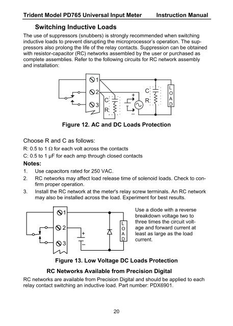
Switching Inductive Loads<br />
The use of suppressors (snubbers) is strongly recommended when switching<br />
inductive loads to prevent disrupting the microprocessor’s operation. The suppressors<br />
also prolong the life of the relay contacts. Suppression can be obtained<br />
with resistor-capacitor (RC) networks assembled by the user or purchased as<br />
complete assemblies. Refer to the following circuits for RC network assembly<br />
and installation:<br />
C<br />
R<br />
C<br />
R<br />
Figure 12. AC and DC Loads Protection<br />
Choose R and C as follows:<br />
R: 0.5 to 1 Ω for each volt across the contacts<br />
C: 0.5 to 1 µF for each amp through closed contacts<br />
Notes:<br />
1. Use capacitors rated for 250 VAC.<br />
2. RC networks may affect load release time of solenoid loads. Check to confirm<br />
proper operation.<br />
3. Install the RC network at the meter's relay screw terminals. An RC network<br />
may also be installed across the load. Experiment for best results.<br />
Use a diode with a reverse<br />
breakdown voltage two to<br />
three times the circuit voltage<br />
and forward current at<br />
least as large as the load<br />
current.<br />
Figure 13. Low Voltage DC Loads Protection<br />
RC Networks Available from Precision Digital<br />
RC networks are available from Precision Digital and should be applied to each<br />
relay contact switching an inductive load. Part number: PDX6901.<br />
20

![ratings & DEFINITIONS452-467_Technical Information[1].pdf](https://img.yumpu.com/49871719/1/190x245/ratings-definitions452-467-technical-information1pdf.jpg?quality=85)