485OTLED - Datasheet - RS-232 to RS-485 Optically ... - Wantronix
485OTLED - Datasheet - RS-232 to RS-485 Optically ... - Wantronix
485OTLED - Datasheet - RS-232 to RS-485 Optically ... - Wantronix

You also want an ePaper? Increase the reach of your titles
YUMPU automatically turns print PDFs into web optimized ePapers that Google loves.
Integrate – Expand – Simplify B&B ELECTRONICS PRODUCT INFORMATION<br />
International Headquarters:<br />
707 Day<strong>to</strong>n Road P.O. Box 1040 Ottawa, IL 61350 USA<br />
815-433-5100 Fax 433-5104 www.bb-elec.com orders@bb-elec.com support@bb-elec.com<br />
Westlink Commercial Park Oranmore Co. Galway Ireland<br />
+353 91 792444 Fax +353 91 792445 www.bb-europe.com orders@bb-elec.com support@bb-europe.com<br />
<strong><strong>485</strong>OTLED</strong>-3803-1/3<br />
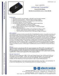
Model <strong><strong>485</strong>OTLED</strong><br />
<strong>RS</strong>-<strong>232</strong> <strong>to</strong> <strong>RS</strong>-<strong>485</strong> <strong>Optically</strong><br />
Isolated Converter CE<br />
Introduction<br />
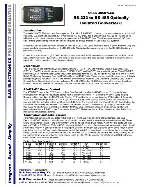
The Model <strong><strong>485</strong>OTLED</strong> is our most feature-packed <strong>RS</strong>-<strong>232</strong> <strong>to</strong> <strong>RS</strong>-422/<strong>485</strong> converter. It converts unbalanced, full or halfduplex<br />
<strong>RS</strong>-<strong>232</strong> signals <strong>to</strong> balanced, full or half-duplex <strong>RS</strong>-422 or <strong>RS</strong>-<strong>485</strong> signals at baud rates up <strong>to</strong> 115.2 kbps. In<br />
addition the unit optically isolates and surge suppresses the <strong>RS</strong>-422/<strong>485</strong> lines. The driver uses au<strong>to</strong>matic SD (send<br />
data) or RTS (handshake) control, or can be configured as always enabled for use in <strong>RS</strong>-422 systems.<br />
A dipswitch selects communication features on the <strong><strong>485</strong>OTLED</strong>. Two LEDs show data traffic in either direction. Only one<br />
power supply is necessary, located on the <strong>RS</strong>-<strong>232</strong> side. The isolated power and ground on the <strong>RS</strong>-422/<strong>485</strong> side are<br />
generated internally.<br />
Connections are made through a DB25 female connec<strong>to</strong>r on the <strong>RS</strong>-<strong>232</strong> side and terminal blocks on the <strong>RS</strong>-422/<strong>485</strong><br />
side. All terminal blocks, dipswitches, and jumpers are located inside the hood and are reachable through the access<br />
panel, which slides closed <strong>to</strong> protect the connections.<br />
Description<br />
The <strong>RS</strong>-<strong>232</strong> port has a female DB25 connec<strong>to</strong>r with pins 2 (TD) 3, (RD), and 7 (Signal Ground) supported, Pins 4<br />
(RTS) and 5 (CTS) are tied <strong>to</strong>gether, and pins 6 (DSR), 8 (CD), and 20 (DTR), are also tied <strong>to</strong>gether. The <strong><strong>485</strong>OTLED</strong><br />
has two LEDs: A Transmit Data LED <strong>to</strong> show when data goes from the <strong>RS</strong>-<strong>232</strong> side <strong>to</strong> the <strong>RS</strong>-<strong>485</strong> side, and a Receive<br />
Data LED showing data going from the <strong>RS</strong>-<strong>485</strong> side <strong>to</strong> the <strong>RS</strong>-<strong>232</strong> side. These are very useful for determining if data is<br />
getting through the converter. The <strong>RS</strong>-<strong>485</strong> terminal blocks support Transmit Data (A) and (B), Receive Data (A) and<br />
(B), and Signal Ground. A single supply voltage of 10 <strong>to</strong> 30 VDC on the <strong>RS</strong>-<strong>232</strong> side powers the unit. An 8-position<br />
dipswitch allows the selection of baud rate, 2-wire or 4-wire mode, echo on or off, and termination in or out.<br />
<strong>RS</strong>-422/<strong>485</strong> Driver Control<br />
The <strong><strong>485</strong>OTLED</strong> uses either RTS Control or Send Data Control <strong>to</strong> enable the <strong>RS</strong>-<strong>485</strong> driver. This option is user<br />
selectable by setting push-on jumpers located next <strong>to</strong> the terminal blocks. RTS controls the driver using <strong>to</strong>ggling<br />
Request <strong>to</strong> Send (pin 4) of the <strong>RS</strong>-<strong>232</strong> side. Raising RTS enables the driver and lowering RTS disables it. Au<strong>to</strong>matic<br />
Send Data Control recognizes the first bit of data from the <strong>RS</strong>-<strong>232</strong> side, enables the transmitter and disables the<br />
receiver. After the last bit of data is sent from the <strong>RS</strong>-<strong>232</strong> side, the timeout waits one character length then disables the<br />
transmitter and enables the receiver. The timeout can be selected with dipswitches or by changing the value of R21<br />
(see Table 1). The timeout is preset at the fac<strong>to</strong>ry for 9600 baud. Removing both sets of jumpers completely will<br />
constantly enable the <strong>RS</strong>-<strong>485</strong> driver. This makes the <strong><strong>485</strong>OTLED</strong> behave like an <strong>RS</strong>-422 converter. See Table 2 for<br />
standard communications settings.<br />
Termination and Echo Options<br />
Termination resistance can be selected with Switch 8 for high baud rates and long cable distances. See B&B<br />
Electronics <strong>RS</strong>-422/<strong>485</strong> Application Note more information (available on the web site or request one by mail). The 4-<br />
wire/2-wire switches (6 and 7) are turned off for 4-wire mode and on for 2-wire mode. When they are set <strong>to</strong> ON, they<br />
connect TD(A) <strong>to</strong> RD(A) and TD(B) <strong>to</strong> RD(B) internally. Switch 5 is controls Echo on and off. When switch 5 is in the off<br />
position the receiver is constantly enabled. Placing the switch in the on position allows the driver or the receiver <strong>to</strong> be<br />
enabled at any time. In 2-wire mode it is recommended that switch 5 be turned on <strong>to</strong> prevent data being sent out from<br />
being “echoed” back through the receiver. Up <strong>to</strong> 32 receivers can be driven by any one <strong>RS</strong>-<strong>485</strong> driver, allowing you <strong>to</strong><br />
put <strong>to</strong>gether large systems with many drop points. Using an <strong>RS</strong>-422/<strong>485</strong> repeater manufactured by B&B Electronics<br />
can increase the number of receivers.<br />
Table 1. Baud Rate Selection<br />
Baud Switch 1 Switch 2 Switch 3 Switch 4 R21 Time out (ms)<br />
1200 OFF OFF OFF OFF 820kΩ 9.0<br />
2400 OFF OFF OFF OFF 410kΩ 4.5<br />
4800 ON OFF OFF OFF Not Used 2.2<br />
9600 OFF ON OFF OFF Not Used 1.1<br />
19200 OFF OFF ON OFF Not Used 0.6<br />
38400 OFF OFF OFF ON Not Used 0.3<br />
57600 OFF OFF ON ON Not Used 0.2<br />
115200 OFF OFF OFF OFF 8.2kΩ 0.1
Integrate – Expand – Simplify B&B ELECTRONICS PRODUCT INFORMATION<br />
Table 2. Standard Communications Settings<br />
Communication<br />
Mode<br />
JP1 Switch 5<br />
Echo<br />
Switch 6<br />
4W/2W<br />
Switch 7<br />
4W/2W<br />
<strong>RS</strong>-422 Mode<br />
Neither OFF OFF OFF<br />
(full duplex)<br />
<strong>RS</strong>-<strong>485</strong> 4-Wire Mode RTS or SD OFF OFF OFF<br />
(full-duplex)<br />
<strong>RS</strong>-<strong>485</strong> 2-Wire Mode<br />
(half-duplex)<br />
RTS or SD ON ON ON<br />
TD A-<br />
TD B+<br />
RD A-<br />
RD B+<br />
422/<strong>485</strong><br />
GND<br />
10 - 30<br />
VDC<br />
<strong>RS</strong>-<strong>232</strong><br />
GND<br />
SW6<br />
SW8<br />
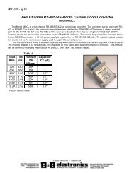
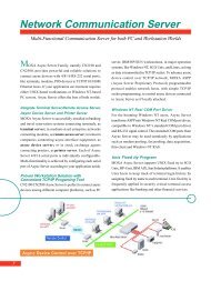
Typical <strong>RS</strong>-422/<strong>485</strong> 2 Wire Setup<br />
<strong><strong>485</strong>OTLED</strong><br />
Rt<br />
SW 7<br />
+<br />
-<br />
Rt<br />
Data A-<br />
Data B+<br />
Power<br />
Supply<br />
2 Wire Device<br />
Rec.<br />
GND<br />
International Headquarters:<br />
707 Day<strong>to</strong>n Road P.O. Box 1040 Ottawa, IL 61350 USA<br />
815-433-5100 Fax 433-5104 www.bb-elec.com orders@bb-elec.com support@bb-elec.com<br />
Enable<br />
Dr.<br />
Westlink Commercial Park Oranmore Co. Galway Ireland<br />
+353 91 792444 Fax +353 91 792445 www.bb-europe.com orders@bb-elec.com support@bb-europe.com<br />
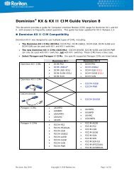
TD A-<br />
TD B+<br />
RD A-<br />
RD B+<br />
422/<strong>485</strong><br />
GND<br />
10 - 30<br />
VDC<br />
<strong>RS</strong>-<strong>232</strong><br />
GND<br />
SW6<br />
SW8<br />
<strong><strong>485</strong>OTLED</strong>-3803-2/3<br />
Typical <strong>RS</strong>-422/<strong>485</strong> 4 Wire Setup<br />
<strong><strong>485</strong>OTLED</strong><br />
Specifications<br />
Dimensions: 2.7 x 5.1 x 0.9 in. (7.0 x 13.0 x 24.0 cm)<br />
Temperature Range: 32 <strong>to</strong> 158°F (0 <strong>to</strong> 70°C)<br />
Supply Voltage: +10 <strong>to</strong> 30 VDC @ 95 mA maximum<br />
Data Rates: Up <strong>to</strong> 115.2 kbs<br />
Connec<strong>to</strong>rs: DB25 female for <strong>RS</strong>-<strong>232</strong><br />
Terminal blocks for <strong>RS</strong>-422/<strong>485</strong> and power<br />
Isolation:<br />
2000 VAC Optical Isolation of Data Signals and Ground<br />
Surge Suppression: 7.5V, bi-directional avalanche breakdown device.<br />
500W peak power dissipation<br />
Clamping time
Integrate – Expand – Simplify B&B ELECTRONICS PRODUCT INFORMATION<br />
International Headquarters:<br />
707 Day<strong>to</strong>n Road P.O. Box 1040 Ottawa, IL 61350 USA<br />
815-433-5100 Fax 433-5104 www.bb-elec.com orders@bb-elec.com support@bb-elec.com<br />
Westlink Commercial Park Oranmore Co. Galway Ireland<br />
+353 91 792444 Fax +353 91 792445 www.bb-europe.com orders@bb-elec.com support@bb-europe.com<br />
<strong><strong>485</strong>OTLED</strong>-3803-3/3