Chapter - Fuels and Combustion - RETScreen International
Chapter - Fuels and Combustion - RETScreen International
Chapter - Fuels and Combustion - RETScreen International

Create successful ePaper yourself
Turn your PDF publications into a flip-book with our unique Google optimized e-Paper software.
Thermal Equipment: <strong>Fuels</strong> <strong>and</strong> <strong>Combustion</strong><br />
FUELS & COMBUSTION<br />
1. INTRODUCTION..........................................................................................................1<br />
2 TYPE OF FUELS............................................................................................................1<br />
3. PERFORMANCE EVALUATION OF FUELS ...............................................11<br />
4. ENERGY EFFICIENCY OPPORTUNITIES...................................................17<br />
5. OPTION CHECKLIST..............................................................................................20<br />
6. WORKSHEETS...........................................................................................................23<br />
7. REFERENCES..............................................................................................................24<br />
1. INTRODUCTION<br />
This section briefly describes the main features of fuels.<br />
Energy from the Sun is converted into chemical energy by photosynthesis. But, as we know,<br />
when we burn dried plants or wood, producing energy in the form of heat <strong>and</strong> light, we are<br />
releasing the Sun’s energy originally stored in that plant or in that wood through<br />
photosynthesis. We know that, in most of the world today, wood is not the main source of<br />
fuel. We generally use natural gas or oil in our homes, <strong>and</strong> we use mainly oil <strong>and</strong> coal to heat<br />
the water to produce the steam to drive the turbines for our huge power generation systems.<br />
These fuels - coal, oil, <strong>and</strong> natural gas - are often referred to as fossil fuels.<br />
The various types of fuels (like liquid, solid <strong>and</strong> gaseous fuels) that are available depend on<br />
various factors such as costs, availability, storage, h<strong>and</strong>ling, pollution <strong>and</strong> l<strong>and</strong>ed boilers,<br />
furnaces <strong>and</strong> other combustion equipments.<br />
The knowledge of the fuel properties helps in selecting the right fuel for the right purpose <strong>and</strong><br />
for the efficient use of the fuel. Laboratory tests are generally used for assessing the nature<br />
<strong>and</strong> quality of fuels.<br />
2 TYPE OF FUELS<br />
This section describes types of fuels: solid, liquid, <strong>and</strong> gaseous.<br />
2.1 Liquid <strong>Fuels</strong><br />
Liquid fuels like furnace oil <strong>and</strong> LSHS (low sulphur heavy stock) are predominantly used in<br />
industrial applications. The various properties of liquid fuels are given below.<br />
2.1.1 Density<br />
Energy Efficiency Guide for Industry in Asia – www.energyefficiencyasia.org ©UNEP 1
Thermal Equipment: <strong>Fuels</strong> <strong>and</strong> <strong>Combustion</strong><br />
Density is defined as the ratio of the mass of the fuel to the volume of the fuel at a reference<br />
temperature of 15°C. Density is measured by an instrument called a hydrometer. The<br />
knowledge of density is useful for quantitative calculations <strong>and</strong> assessing ignition qualities.<br />
The unit of density is kg/m3.<br />
2.1.2 Specific gravity<br />
This is defined as the ratio of the weight of a given volume of oil to the weight of the same<br />
volume of water at a given temperature. The density of fuel, relative to water, is called<br />
specific gravity. The specific gravity of water is defined as 1. Since specific gravity is a ratio,<br />
it has no units. The measurement of specific gravity is generally made by a hydrometer.<br />
Specific gravity is used in calculations involving weights <strong>and</strong> volumes. The specific gravity<br />
of various fuel oils are given in Table below:<br />
Table 1. Specific gravity of various fuel oils (adapted from Thermax India Ltd.)<br />
Fuel Oil<br />
L.D.O<br />
(Light Diesel Oil)<br />
Furnace oil L.S.H.S<br />
(Low Sulphur<br />
Heavy Stock)<br />
Specific Gravity 0.85 - 0.87 0.89 - 0.95 0.88 - 0.98<br />
2.1.3 Viscosity<br />
The viscosity of a fluid is a measure of its internal resistance to flow. Viscosity depends on<br />
the temperature <strong>and</strong> decreases as the temperature increases. Any numerical value for<br />
viscosity has no meaning unless the temperature is also specified. Viscosity is measured in<br />
Stokes / Centistokes. Sometimes viscosity is also quoted in Engler, Saybolt or Redwood.<br />
Each type of oil has its own temperature - viscosity relationship. The measurement of<br />
viscosity is made with an instrument called a Viscometer.<br />
Viscosity is the most important characteristic in the storage <strong>and</strong> use of fuel oil. It influences<br />
the degree of pre-heating required for h<strong>and</strong>ling, storage <strong>and</strong> satisfactory atomization. If the<br />
oil is too viscous, it may become difficult to pump, hard to light the burner, <strong>and</strong> difficult to<br />
h<strong>and</strong>le. Poor atomization may result in the formation of carbon deposits on the burner tips or<br />
on the walls. Therefore pre-heating is necessary for proper atomization.<br />
2.1.4 Flash Point<br />
The flash point of a fuel is the lowest temperature at which the fuel can be heated so that the<br />
vapour gives off flashes momentarily when an open flame is passed over it. The flash point<br />
for furnace oil is 66 0 C.<br />
2.1.5 Pour Point<br />
The pour point of a fuel is the lowest temperature at which it will pour or flow when cooled<br />
under prescribed conditions. It is a very rough indication of the lowest temperature at which<br />
fuel oil is ready to be pumped.<br />
2.1.6 Specific Heat<br />
Energy Efficiency Guide for Industry in Asia – www.energyefficiencyasia.org ©UNEP 2
Thermal Equipment: <strong>Fuels</strong> <strong>and</strong> <strong>Combustion</strong><br />
Specific heat is the amount of kCals needed to raise the temperature of 1 kg of oil by 1 0 C.<br />
The unit of specific heat is kcal/kg 0 C. It varies from 0.22 to 0.28 depending on the oil specific<br />
gravity. The specific heat determines how much steam or electrical energy it takes to heat oil<br />
to a desired temperature. Light oils have a low specific heat, whereas heavier oils have a<br />
higher specific heat.<br />
2.1.7 Calorific Value<br />
The calorific value is the measurement of heat or energy produced, <strong>and</strong> is measured either as<br />
gross calorific value or net calorific value. The difference is determined by the latent heat of<br />
condensation of the water vapour produced during the combustion process. Gross calorific<br />
value (GCV) assumes all vapour produced during the combustion process is fully condensed.<br />
Net calorific value (NCV) assumes the water leaves with the combustion products without<br />
fully being condensed. <strong>Fuels</strong> should be compared based on the net calorific value.<br />
The calorific value of coal varies considerably depending on the ash, moisture content <strong>and</strong><br />
the type of coal while calorific value of fuel oils are much more consistent. The typical GCVs<br />
of some of the commonly used liquid fuels are given below:<br />
Table 2. Gross calorific values for different fuel oils (adapted from Thermax India Ltd.)<br />
Fuel Oil<br />
Gross Calorific Value (kCal/kg)<br />
Kerosene - 11,100<br />
Diesel Oil - 10,800<br />
L.D.O - 10,700<br />
Furnace Oil - 10,500<br />
LSHS - 10,600<br />
2.1.8 Sulphur<br />
The amount of sulphur in the fuel oil depends mainly on the source of the crude oil <strong>and</strong> to a<br />
lesser extent on the refining process. The normal sulfur content for the residual fuel oil<br />
(furnace oil) is in the order of 2 - 4 %. Typical figures for different fuel oils are shown in<br />
Table 3.<br />
Table 3. Percentages of sulphur for different fuel oils (adapted from Thermax India Ltd.)<br />
Fuel oil<br />
Percentage of Sulphur<br />
Kerosene 0.05 - 0.2<br />
Diesel Oil 0.05 - 0.25<br />
L.D.O 0.5 - 1.8<br />
Furnace Oil 2.0 - 4.0<br />
LSHS < 0.5<br />
The main disadvantage of sulphur is the risk of corrosion by sulphuric acid formed during<br />
<strong>and</strong> after combustion, <strong>and</strong> condensation in cool parts of the chimney or stack, air pre-heater<br />
<strong>and</strong> economizer.<br />
2.1.9 Ash Content<br />
Energy Efficiency Guide for Industry in Asia – www.energyefficiencyasia.org ©UNEP 3
Thermal Equipment: <strong>Fuels</strong> <strong>and</strong> <strong>Combustion</strong><br />
The ash value is related to the inorganic material or salts in the fuel oil. The ash levels in<br />
distillate fuels are negligible. Residual fuels have higher ash levels. These salts may be<br />
compounds of sodium, vanadium, calcium, magnesium, silicon, iron, aluminum, nickel, etc.<br />
Typically, the ash value is in the range 0.03 - 0.07 %. Excessive ash in liquid fuels can cause<br />
fouling deposits in the combustion equipment. Ash has an erosive effect on the burner tips,<br />
causes damage to the refractories at high temperatures <strong>and</strong> gives rise to high temperature<br />
corrosion <strong>and</strong> fouling of equipments.<br />
2.1.10 Carbon Residue<br />
Carbon residue indicates the tendency of oil to deposit a carbonaceous solid residue on a hot<br />
surface, such as a burner or injection nozzle, when its vaporizable constituents evaporate.<br />
Residual oil contains carbon residue of 1 percent or more.<br />
2.1.11 Water Content<br />
The water content of furnace oil when it is supplied is normally very low because the product<br />
at refinery site is h<strong>and</strong>led hot. An upper limit of 1% is specified as a st<strong>and</strong>ard.<br />
Water may be present in free or emulsified form <strong>and</strong> can cause damage to the inside surfaces<br />
of the furnace during combustion especially if it contains dissolved salts. It can also cause<br />
spluttering of the flame at the burner tip, possibly extinguishing the flame, reducing the flame<br />
temperature or lengthening the flame.<br />
Typical specifications of fuel oils are summarized in the Table below.<br />
Table 4. Typical specifications of fuel oils (adapted from Thermax India Ltd.)<br />
Properties<br />
Fuel Oils<br />
Furnace Oil L.S.H.S L.D.O<br />
Density (Approx. 0.89 - 0.95 0.88 - 0.98 0.85 - 0.87<br />
g/cc at 150C)<br />
Flash Point (0C) 66 93 66<br />
Pour Point (0C) 20 72 18<br />
G.C.V. (kCal/kg) 10500 10600 10700<br />
Sediment, % Wt.<br />
0.25 0.25 0.1<br />
Max.<br />
Sulphur Total, % Up to 4.0 Up to 0.5 Up to 1.8<br />
Wt. Max.<br />
Water Content, %<br />
1.0 1.0 0.25<br />
Vol. Max.<br />
Ash % Wt. Max. 0.1 0.1 0.02<br />
2.1.12 Storage of Fuel oil<br />
It can be potentially hazardous to store furnace oil in barrels. A better practice is to store it in<br />
cylindrical tanks, either above or below the ground. Furnace oil that is delivered may contain<br />
dust, water <strong>and</strong> other contaminants.<br />
Energy Efficiency Guide for Industry in Asia – www.energyefficiencyasia.org ©UNEP 4
Thermal Equipment: <strong>Fuels</strong> <strong>and</strong> <strong>Combustion</strong><br />
The sizing of the storage tank facility is very important. A recommended storage size<br />
estimate is to provide for at least 10 days of normal consumption. Industrial heating fuel<br />
storage tanks are generally vertical mild steel tanks mounted above the ground. It is prudent<br />
for safety <strong>and</strong> environmental reasons to build bund walls around tanks to contain accidental<br />
spillages.<br />
As a certain amount of settlement of solids <strong>and</strong> sludge will occur in tanks over time, tanks<br />
should be cleaned at regular intervals: annually for heavy fuels <strong>and</strong> every two years for light<br />
fuels. Care should be taken when oil is decanted from the tanker to the storage tank. All leaks<br />
from joints, flanges <strong>and</strong> pipelines must be attended to at the earliest. Fuel oil should be free<br />
from possible contaminants such as dirt, sludge <strong>and</strong> water before it is fed to the combustion<br />
system.<br />
2.2 Solid Fuel (Coal)<br />
2.2.1 Coal classification<br />
Coal is classified into three major types namely anthracite, bituminous, <strong>and</strong> lignite. However,<br />
there is no clear demarcation between them. Coal is further classified as semi-anthracite,<br />
semi-bituminous, <strong>and</strong> sub-bituminous. Anthracite is the oldest coal from a geological<br />
perspective. It is a hard coal composed mainly of carbon with little volatile content <strong>and</strong><br />
practically no moisture. Lignite is the youngest coal from a geological perspective. It is a soft<br />
coal composed mainly of volatile matter <strong>and</strong> moisture content with low fixed carbon. Fixed<br />
carbon refers to carbon in its free state, not combined with other elements. Volatile matter<br />
refers to those combustible constituents of coal that vaporize when coal is heated.<br />
The common coals used in for example Indian industry are bituminous <strong>and</strong> sub-bituminous<br />
coal. The gradation of Indian coal based on its calorific value is as follows:<br />
Grade Calorific Value Range<br />
(in kCal/kg)<br />
A Exceeding 6200<br />
B 5600 –6200<br />
C 4940 –5600<br />
D 4200 –4940<br />
E 3360 –4200<br />
F 2400 –3360<br />
G 1300 –2400<br />
Normally D, E <strong>and</strong> F coal grades are available to Indian industry.<br />
The chemical composition of coal has a strong influence on its combustibility. The properties<br />
of coal are broadly classified as physical properties <strong>and</strong> chemical properties.<br />
2.2.2 Physical <strong>and</strong> chemical properties of coal<br />
Physical properties of coal include the heating value, moisture content, volatile matter <strong>and</strong><br />
ash.<br />
Energy Efficiency Guide for Industry in Asia – www.energyefficiencyasia.org ©UNEP 5
Thermal Equipment: <strong>Fuels</strong> <strong>and</strong> <strong>Combustion</strong><br />
The chemical properties of coal refer to the various elemental chemical constituents such as<br />
carbon, hydrogen, oxygen, <strong>and</strong> sulphur.<br />
The heating value of coal varies from coal field to coal field. The typical GCVs for various<br />
coals are given in the Table below.<br />
Table 5. GCV for various coal types<br />
Parameter Lignite<br />
(Dry Basis)<br />
Indian Coal Indonesian<br />
Coal<br />
South African<br />
Coal<br />
GCV (kCal/kg)<br />
4,500 * 4,000 5,500 6,000<br />
*GCV of lignite on ‘as received basis’is 2500 –3000<br />
2.2.3 Analysis of coal<br />
There are two methods to analyze coal: ultimate analysis <strong>and</strong> proximate analysis. The<br />
ultimate analysis determines all coal component elements, solid or gaseous <strong>and</strong> the proximate<br />
analysis determines only the fixed carbon, volatile matter, moisture <strong>and</strong> ash percentages. The<br />
ultimate analysis is determined in a properly equipped laboratory by a skilled chemist, while<br />
proximate analysis can be determined with a simple apparatus. (It may be noted that<br />
proximate has no connection with the word “approximate”).<br />
Measurement of moisture<br />
The determination of moisture content is carried out by placing a sample of powdered raw<br />
coal of size 200-micron size in an uncovered crucible, which is placed in the oven kept at 108<br />
+2 o C along with the lid. Then the sample is cooled to room temperature <strong>and</strong> weighed again.<br />
The loss in weight represents moisture.<br />
Measurement of volatile matter<br />
A fresh sample of crushed coal is weighed, placed in a covered crucible, <strong>and</strong> heated in a<br />
furnace at 900 + 15 o C. The sample is cooled <strong>and</strong> weighed. Loss of weight represents<br />
moisture <strong>and</strong> volatile matter. The remainder is coke (fixed carbon <strong>and</strong> ash). For detailed<br />
methodologies (including for determination of carbon <strong>and</strong> ash content), refer to IS 1350 part<br />
I: 1984, part III, IV.<br />
Measurement of carbon <strong>and</strong> ash<br />
The cover from the crucible used in the last test is removed <strong>and</strong> the crucible is heated over the<br />
Bunsen burner until all the carbon is burned. The residue is weighed, which is the<br />
incombustible ash. The difference in weight from the previous weighing is the fixed carbon.<br />
In actual practice Fixed Carbon or FC derived by subtracting from 100 the value of moisture,<br />
volatile matter <strong>and</strong> ash.<br />
Proximate analysis<br />
The proximate analysis indicates the percentage by weight of fixed carbon, volatiles, ash, <strong>and</strong><br />
moisture content in coal. The amounts of fixed carbon <strong>and</strong> volatile combustible matter<br />
directly contribute to the heating value of coal. Fixed carbon acts as a main heat generator<br />
during burning. High volatile matter content indicates easy ignition of fuel. The ash content is<br />
important in the design of the furnace grate, combustion volume, pollution control equipment<br />
<strong>and</strong> ash h<strong>and</strong>ling systems of a furnace. A typical proximate analysis of various coal types is<br />
given in Table 6.<br />
Energy Efficiency Guide for Industry in Asia – www.energyefficiencyasia.org ©UNEP 6
Thermal Equipment: <strong>Fuels</strong> <strong>and</strong> <strong>Combustion</strong><br />
Table 6. Typical proximate analysis of various coals (percentage)<br />
Parameter Indian Coal Indonesian Coal South African Coal<br />
Moisture 5.98 9.43 8.5<br />
Ash 38.63 13.99 17<br />
Volatile matter 20.70 29.79 23.28<br />
Fixed Carbon 34.69 46.79 51.22<br />
These parameters are described below.<br />
Fixed carbon:<br />
Fixed carbon is the solid fuel left in the furnace after volatile matter is distilled off. It consists<br />
mostly of carbon but also contains some hydrogen, oxygen, sulphur <strong>and</strong> nitrogen not driven<br />
off with the gases. Fixed carbon gives a rough estimate of the heating value of coal.<br />
Volatile matter:<br />
Volatile matters are the methane, hydrocarbons, hydrogen <strong>and</strong> carbon monoxide, <strong>and</strong><br />
incombustible gases like carbon dioxide <strong>and</strong> nitrogen found in coal. Thus the volatile matter<br />
is an index of the gaseous fuels present. A typical range of volatile matter is 20 to 35%.<br />
Volatile matter:<br />
• Proportionately increases flame length, <strong>and</strong> helps in easier ignition of coal<br />
• Sets minimum limit on the furnace height <strong>and</strong> volume<br />
• Influences secondary air requirement <strong>and</strong> distribution aspects<br />
• Influences secondary oil support<br />
Ash content:<br />
Ash is an impurity that will not burn. Typical range is 5% to 40%. Ash<br />
• Reduces h<strong>and</strong>ling <strong>and</strong> burning capacity<br />
• Increases h<strong>and</strong>ling costs<br />
• Affects combustion efficiency <strong>and</strong> boiler efficiency<br />
• Causes clinkering <strong>and</strong> slagging<br />
Moisture content:<br />
Moisture in coal must be transported, h<strong>and</strong>led <strong>and</strong> stored. Since it replaces combustible<br />
matter, it decreases the heat content per kg of coal. Typical range is 0.5 to 10%. Moisture:<br />
• Increases heat loss, due to evaporation <strong>and</strong> superheating of vapour<br />
• Helps to a certain extent with binding fines<br />
• Aids radiation heat transfer<br />
Sulphur content:<br />
Typical range is 0.5 to 0.8% normally. Sulphur:<br />
• Affects clinkering <strong>and</strong> slagging tendencies<br />
• Corrodes chimney <strong>and</strong> other equipment such as air heaters <strong>and</strong> economizers<br />
• Limits exit flue gas temperature<br />
Ultimate analysis<br />
Energy Efficiency Guide for Industry in Asia – www.energyefficiencyasia.org ©UNEP 7
Thermal Equipment: <strong>Fuels</strong> <strong>and</strong> <strong>Combustion</strong><br />
The ultimate analysis indicates the various elemental chemical constituents such as carbon,<br />
hydrogen, oxygen, sulphur, etc. It is useful in determining the quantity of air required for<br />
combustion <strong>and</strong> the volume <strong>and</strong> composition of the combustion gases. This information is<br />
required for the calculation of flame temperature <strong>and</strong> the flue duct design etc. Typical<br />
ultimate analyses of various coals are given in the table below.<br />
Table 7. Typical ultimate analysis of coals<br />
Parameter Indian Coal, % Indonesian Coal, %<br />
Moisture 5.98 9.43<br />
Mineral Matter (1.1 x Ash) 38.63 13.99<br />
Carbon 41.11 58.96<br />
Hydrogen 2.76 4.16<br />
Nitrogen 1.22 1.02<br />
Sulphur 0.41 0.56<br />
Oxygen 9.89 11.88<br />
Table 8. Relationship between ultimate analysis <strong>and</strong> proximate analysis<br />
%C = 0.97C+ 0.7(VM - 0.1A) - M(0.6-0.01M)<br />
%H =<br />
0.036C + 0.086 (VM -0.1xA) - 0.0035M 2 (1-0.02M)<br />
%N<br />
2<br />
= 2.10 -0.020 VM<br />
Where<br />
C = % of fixed carbon<br />
A = % of ash<br />
VM = % of volatile matter<br />
M = % of moisture<br />
Note: the above equation is valid for coal with a greater than 15% moisture content<br />
2.2.4 Storage, h<strong>and</strong>ling <strong>and</strong> preparation of coal<br />
Uncertainty in the availability <strong>and</strong> transportation of fuel necessitates storage <strong>and</strong> subsequent<br />
h<strong>and</strong>ling. Storing coal has its own disadvantages like build-up of inventory, space constraints,<br />
deterioration in quality <strong>and</strong> potential fire hazards. Other minor losses associated with the<br />
storage of coal include oxidation, wind <strong>and</strong> carpet loss. A 1% oxidation of coal has the same<br />
effect as 1% ash in coal. Wind losses may account for nearly 0.5 –1.0 % of the total loss.<br />
The main goal of good coal storage is to minimize carpet loss <strong>and</strong> the loss due to spontaneous<br />
combustion. Formation of a soft carpet, comprising of coal dust <strong>and</strong> soil, causes carpet loss.<br />
On the other h<strong>and</strong>, if the temperature gradually rises in a coal heap, then oxidation may lead<br />
to spontaneous combustion of coal stored. Carpet losses can be reduced by:<br />
1. Preparing a hard solid surface for coal to be stored<br />
2. Preparing st<strong>and</strong>ard storage bays of concrete <strong>and</strong> brick<br />
In industry, coal h<strong>and</strong>ling methods range from manual <strong>and</strong> conveyor systems. It would be<br />
advisable to minimize the h<strong>and</strong>ling of coal so that further generation of fines <strong>and</strong> segregation<br />
effects are reduced.<br />
Energy Efficiency Guide for Industry in Asia – www.energyefficiencyasia.org ©UNEP 8
Thermal Equipment: <strong>Fuels</strong> <strong>and</strong> <strong>Combustion</strong><br />
The preparation of coal prior to feeding into the boiler is an important step for achieving good<br />
combustion. Large <strong>and</strong> irregular lumps of coal may cause the following problems:<br />
• Poor combustion conditions <strong>and</strong> inadequate furnace temperature<br />
• Higher excess air resulting in higher stack loss<br />
• Increase of unburnts in the ash<br />
• Low thermal efficiency<br />
Note: A detailed description for the preparation of coal is given under the section “Energy<br />
Efficiency Opportunities”.<br />
2.3 Gaseous Fuel<br />
Gas fuels are the most convenient because they require the least amount of h<strong>and</strong>ling <strong>and</strong> are<br />
used in the simplest <strong>and</strong> most maintenance-free burner systems. Gas is delivered "on tap" via<br />
a distribution network <strong>and</strong> so is suited for areas with a high population or industrial density.<br />
However, large individual consumers do have gasholders <strong>and</strong> some produce their own gas.<br />
2.3.1 Types of gaseous fuel<br />
The following is a list of the types of gaseous fuel:<br />
• <strong>Fuels</strong> naturally found in nature:<br />
− Natural gas<br />
− Methane from coal mines<br />
• Fuel gases made from solid fuel<br />
− Gases derived from coal<br />
− Gases derived from waste <strong>and</strong> biomass<br />
− From other industrial processes (blast furnace gas)<br />
• Gases made from petroleum<br />
− Liquefied Petroleum gas (LPG)<br />
− Refinery gases<br />
− Gases from oil gasification<br />
• Gases from some fermentation process<br />
Gaseous fuels in common use are liquefied petroleum gases (LPG), Natural gas, producer<br />
gas, blast furnace gas, coke oven gas etc. The calorific value of gaseous fuel is expressed in<br />
Kilocalories per normal cubic meter (kCal/Nm 3 ) i.e. at normal temperature (20 0 C) <strong>and</strong><br />
pressure (760 mm Hg).<br />
2.3.2 Properties of gaseous fuels<br />
Since most gas combustion appliances cannot utilize the heat content of the water vapour,<br />
gross calorific value is of little interest. Fuel should be compared based on the net calorific<br />
value. This is especially true for natural gas, since increased hydrogen content results in high<br />
water formation during combustion.<br />
Typical physical <strong>and</strong> chemical properties of various gaseous fuels are given in Table 9.<br />
Energy Efficiency Guide for Industry in Asia – www.energyefficiencyasia.org ©UNEP 9
Thermal Equipment: <strong>Fuels</strong> <strong>and</strong> <strong>Combustion</strong><br />
Table 9. Typical physical <strong>and</strong> chemical properties of various gaseous fuels<br />
Fuel Gas Relative Higher Heating Air/Fuel Flame Flame<br />
Density Value kcal/Nm 3 ratiom<br />
of air to m 3 Temp. o C<br />
Speed m/s<br />
of Fuel<br />
Natural 0.6 9350 10 1954 0.290<br />
Gas<br />
Propane 1.52 22200 25 1967 0.460<br />
Butane 1.96 28500 32 1973 0.870<br />
2.3.3 LPG<br />
LPG is a predominant mixture of propane <strong>and</strong> Butane with a small percentage of unsaturates<br />
(Propylene <strong>and</strong> Butylene) <strong>and</strong> some lighter C<br />
2<br />
as well as heavier C<br />
5<br />
fractions. Included in the<br />
LPG range are propane (C<br />
3<br />
H<br />
8<br />
), Propylene(C<br />
3<br />
H<br />
6<br />
), normal <strong>and</strong> iso-butane (C<br />
4<br />
H<br />
10<br />
)<strong>and</strong><br />
Butylene(C<br />
4<br />
H<br />
8<br />
). LPG may be defined as those hydrocarbons, which are gaseous at normal<br />
atmospheric pressure, but may be condensed to the liquid state at normal temperature, by the<br />
application of moderate pressures. Although they are normally used as gases, they are stored<br />
<strong>and</strong> transported as liquids under pressure for convenience <strong>and</strong> ease of h<strong>and</strong>ling. Liquid LPG<br />
evaporates to produce about 250 times volume of gas.<br />
LPG vapour is denser than air: butane is about twice as heavy as air <strong>and</strong> propane about one<br />
<strong>and</strong> a half times as heavy as air. Consequently, the vapour may flow along the ground <strong>and</strong><br />
into drains sinking to the lowest level of the surroundings <strong>and</strong> be ignited at a considerable<br />
distance from the source of leakage. In still air vapour will disperse slowly. Escape of even<br />
small quantities of the liquefied gas can give rise to large volumes of vapour / air mixture <strong>and</strong><br />
thus cause considerable hazard. To aid in the detection of atmospheric leaks, all LPG’s are<br />
required to be odorized. There should be adequate ground level ventilation where LPG is<br />
stored. For this very reason LPG cylinders should not be stored in cellars or basements,<br />
which have no ventilation at ground level.<br />
2.3.4 Natural gas<br />
Methane is the main constituent of natural gas <strong>and</strong> accounting for about 95% of the total<br />
volume. Other components are: Ethane, Propane, Butane, Pentane, Nitrogen, Carbon<br />
Dioxide, <strong>and</strong> traces of other gases. Very small amounts of sulphur compounds are also<br />
present. Since methane is the largest component of natural gas, generally properties of<br />
methane are used when comparing the properties of natural gas to other fuels.<br />
Natural gas is a high calorific value fuel requiring no storage facilities. It mixes with air<br />
readily <strong>and</strong> does not produce smoke or soot. It contains no sulphur. It is lighter than air <strong>and</strong><br />
disperses into air easily in case of leak. A typical comparison of carbon contents in oil, coal<br />
<strong>and</strong> gas is given in the table below.<br />
Energy Efficiency Guide for Industry in Asia – www.energyefficiencyasia.org ©UNEP 10
Thermal Equipment: <strong>Fuels</strong> <strong>and</strong> <strong>Combustion</strong><br />
Table 10. Comparison of chemical composition of various fuels<br />
Fuel Oil Coal Natural Gas<br />
Carbon 84 41.11 74<br />
Hydrogen 12 2.76 25<br />
Sulphur 3 0.41 -<br />
Oxygen 1 9.89 Trace<br />
Nitrogen Trace 1.22 0.75<br />
Ash Trace 38.63 -<br />
Water Trace 5.98 -<br />
3. PERFORMANCE EVALUATION OF FUELS<br />
This section explains the principles of combustion, how fuel performance can be evaluated<br />
using the stochiometric calculation of air requirement, the concept of excess air, <strong>and</strong> the draft<br />
system of exhaust gases.<br />
3.1 Principles of <strong>Combustion</strong><br />
3.1.1 <strong>Combustion</strong> process<br />
<strong>Combustion</strong> refers to the rapid oxidation of fuel accompanied by the production of heat, or<br />
heat <strong>and</strong> light. Complete combustion of a fuel is possible only in the presence of an adequate<br />
supply of oxygen.<br />
Oxygen (O 2 ) is one of the most common elements on earth making up 20.9% of our air.<br />
Rapid fuel oxidation results in large amounts of heat. Solid or liquid fuels must be changed to<br />
a gas before they will burn. Usually heat is required to change liquids or solids into gases.<br />
Fuel gases will burn in their normal state if enough air is present.<br />
Most of the 79% of air (that is not oxygen) is nitrogen, with traces of other elements.<br />
Nitrogen is considered to be a temperature reducing diluter that must be present to obtain the<br />
oxygen required for combustion.<br />
Nitrogen reduces combustion efficiency by absorbing heat from the combustion of fuels <strong>and</strong><br />
diluting the flue gases. This reduces the heat available for transfer through the heat exchange<br />
surfaces. It also increases the volume of combustion by-products, which then have to travel<br />
through the heat exchanger <strong>and</strong> up the stack faster to allow the introduction of additional<br />
fuel-air mixture.<br />
This nitrogen also can combine with oxygen (particularly at high flame temperatures) to<br />
produce oxides of nitrogen (NO x ), which are toxic pollutants. Carbon, hydrogen <strong>and</strong> sulphur<br />
in the fuel combine with oxygen in the air to form carbon dioxide, water vapour <strong>and</strong> sulphur<br />
dioxide, releasing 8,084 kcals, 28,922 kcals <strong>and</strong> 2,224 kcals of heat respectively. Under<br />
certain conditions, carbon may also combine with oxygen to form carbon monoxide, which<br />
results in the release of a smaller quantity of heat (2,430 kcals/kg of carbon). Carbon burned<br />
to CO2 will produce more heat per unit of fuel than when CO or smoke are produced.<br />
Energy Efficiency Guide for Industry in Asia – www.energyefficiencyasia.org ©UNEP 11
Thermal Equipment: <strong>Fuels</strong> <strong>and</strong> <strong>Combustion</strong><br />
C + O 2 → CO 2 + 8,084 kcals/kg of Carbon<br />
2C + O 2 → 2 CO + 2,430 kcals/kg of Carbon<br />
2H 2 + O 2 → 2H 2 O + 28,922 kcals/kg of Hydrogen<br />
S + O 2 → SO 2 + 2,224 kcals/kg of Sulphur<br />
Each kilogram of CO formed means a loss of 5654 kCal of heat (8084 –2430).<br />
3.1.2 Three T’s of combustion<br />
The objective of good combustion is to release all of the heat in the fuel. This is<br />
accomplished by controlling the "three T's" of combustion which are (1) Temperature high<br />
enough to ignite <strong>and</strong> maintain ignition of the fuel, (2) Turbulence or intimate mixing of the<br />
fuel <strong>and</strong> oxygen, <strong>and</strong> (3) Time, sufficient for complete combustion.<br />
Commonly used fuels like natural gas <strong>and</strong> propane generally consist of carbon <strong>and</strong> hydrogen.<br />
Water vapor is a by-product of burning hydrogen. This removes heat from the flue gases,<br />
which would otherwise be available for more heat transfer.<br />
Natural gas contains more hydrogen <strong>and</strong> less carbon per kg than fuel oils <strong>and</strong> as such<br />
produces more water vapor. Consequently, more heat will be carried away by exhaust while<br />
firing natural gas.<br />
Too much, or too little fuel with the available combustion air may potentially result in<br />
unburned fuel <strong>and</strong> carbon monoxide generation. A very specific amount of O2 is needed for<br />
perfect combustion <strong>and</strong> some additional (excess) air is required for ensuring complete<br />
combustion. However, too much excess air will result in heat <strong>and</strong> efficiency losses.<br />
Not all of the fuel is converted to heat <strong>and</strong> absorbed by the steam generation equipment.<br />
Usually all of the hydrogen in the fuel is burned <strong>and</strong> most boiler fuels, allowable with today's<br />
air pollution st<strong>and</strong>ards, contain little or no sulfur. So the main challenge in combustion<br />
efficiency is directed toward unburned carbon (in the ash or incompletely burned gas), which<br />
forms CO instead of CO2.<br />
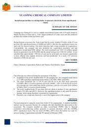
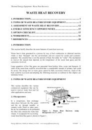
Figure 1. Perfect, good <strong>and</strong> incomplete combustion<br />
(Bureau of Energy Efficiency, 2004)<br />
Energy Efficiency Guide for Industry in Asia – www.energyefficiencyasia.org ©UNEP 12
Thermal Equipment: <strong>Fuels</strong> <strong>and</strong> <strong>Combustion</strong><br />
3.2 Stochiometric Calculation of Air Requirement<br />
3.2.1 Calculation of stochiometric air needed for combustion of furnace oil<br />
For combustion air is needed. The amount of air needed can be calculated using the method<br />
given below.<br />
The first step is to determine the composition of the furnace oil. Typical specifications of<br />
furnace oil from lab analysis is given below:<br />
Constituents<br />
% By weight<br />
Carbon 85.9<br />
Hydrogen 12<br />
Oxygen 0.7<br />
Nitrogen 0.5<br />
Sulphur 0.5<br />
H2O 0.35<br />
Ash 0.05<br />
GCV of fuel<br />
10880 kcal/kg<br />
If we take these analysis data, <strong>and</strong> considering a sample of 100 kg of furnace oil, then the<br />
chemical reactions are as follows:<br />
Element<br />
Molecular Weight (kg / kg mole)<br />
C 12<br />
O2 32<br />
H2 2<br />
S 32<br />
N2 28<br />
CO2 44<br />
SO2 64<br />
H2O 18<br />
C + O2 → CO2<br />
H2 + 1/2O2 → H2O<br />
S + O2 → SO2<br />
Constituents of fuel<br />
C + O2 → CO2<br />
12 + 32 → 44<br />
12 kg of carbon requires 32 kg of oxygen to form 44 kg of carbon dioxide therefore 1 kg of<br />
carbon requires 32/12 kg i.e 2.67 kg of oxygen<br />
(85.9) C + (85.9 x 2.67) O2 → 315.25 CO2<br />
2H2 + O2 → 2H2O<br />
4 + 32 → 36<br />
4 kg of hydrogen requires 32 kg of oxygen to form 36 kg of water, therefore 1 kg of hydrogen<br />
requires 32/4 kg i.e. 8 kg of oxygen.<br />
Energy Efficiency Guide for Industry in Asia – www.energyefficiencyasia.org ©UNEP 13
Thermal Equipment: <strong>Fuels</strong> <strong>and</strong> <strong>Combustion</strong><br />
(12) H2 + (12 x 8) O2 → (12 x 9 ) H2O<br />
S + O2 → SO2<br />
32 + 32 → 64<br />
32 kg of sulphur requires 32 kg of oxygen to form 64 kg of sulphur dioxide, therefore 1 kg of<br />
sulphur requires 32/32 kg i.e. 1 kg of oxygen<br />
(0.5) S + (0.5 x 1) O2 → 1.0 SO2<br />
Total oxygen required = 325.57 kg<br />
(229.07+96+0.5)<br />
Oxygen already present in<br />
100 kg fuel (given) = 0.7 kg<br />
Additional oxygen required = 325.57 –0.7<br />
= 324.87 kg<br />
Therefore quantity of dry air needed = (324.87) / 0.23<br />
(air contains 23% oxygen by weight)<br />
= 1412.45 kg of air<br />
Theoretical air required = (1412.45) / 100<br />
= 14.12 kg of air / kg of fuel<br />
Therefore, in this example, for each kg of furnace oil burnt, 14.12 kg of air is required.<br />
3.2.2 Calculation of theoretical CO2 content in the flue gases<br />
It is necessary to also calculate the CO2 content in the flue gases, which then can be used to<br />
calculate the excess air in the flue gases. A certain amount of excess air is needed for<br />
complete combustion of furnace oils. However, too much excess air points to heat losses <strong>and</strong><br />
too little excess air points to incomplete combustion. The CO2 in flue gases can be<br />
calculated as follows:<br />
Nitrogen in flue gas = 1412.45 –324.87<br />
= 1087.58 kg<br />
Theoretical CO2% in dry flue gas by volume is calculated as below:<br />
Moles of CO2 in flue gas = (314.97) / 44 = 7.16<br />
Moles of N2 in flue gas = (1087.58) / 28 = 38.84<br />
Moles of SO2 in flue gas = 1/64 = 0.016<br />
Theoretical CO2 % by Volume<br />
= (Moles of CO2 x 100) / Total Moles (Dry)<br />
= (7.16 x 100) / (7.16 + 38.84 + 0.016)<br />
= 15.5%<br />
Energy Efficiency Guide for Industry in Asia – www.energyefficiencyasia.org ©UNEP 14
Thermal Equipment: <strong>Fuels</strong> <strong>and</strong> <strong>Combustion</strong><br />
3.2.3 Calculation of constituents of flue gas with excess air<br />
Now we know the theoretical air requirements <strong>and</strong> the theoretical CO2 content of flue gases.<br />
The next step is to measure the actual CO2 percentage in the flue gases. In the calculation<br />
below it is assumed that the measured %CO2 in the flue gas is 10%.<br />
% Excess air = [(Theoretical CO2%/Actual CO2) –1] x 100<br />
= [(15.5/10 –1)] x 100<br />
= 55%<br />
Theoretical air required for 100kg of fuel burnt = 1412.45 kg<br />
Total quantity of air supply required with 55% excess air = 1412.45 x 1.55<br />
= 2189.30 kg<br />
Excess air quantity (actual –theoretical excess air) = 2189.30 –1412.45<br />
= 776.85<br />
O 2 (23%) = 776.85 x 0.23<br />
= 178.68 kg<br />
N2 (77%) = 776.85 –178.68<br />
= 598.17 kg<br />
The final constituents of flue gas with 55% excess air for every 100 kg fuel is as follows:<br />
CO2 = 314.97 kg<br />
H2O = 108.00 kg<br />
SO2 = 1 kg<br />
O2 = 178.68 kg<br />
N2 = 1685.75 kg (= 1087.58 in air + 598.17 in excess air)<br />
3.2.4 Calculation of theoretical CO2% in dry flue gas by volume<br />
Now that we have the constituents by weight, we can calculate the constituents on a volume<br />
basis as follows:<br />
Moles of CO2 in flue gas = 314.97 / 44 = 7.16<br />
Moles of SO2 in flue gas = 1/64 = 0.016<br />
Moles of O2 in flue gas = 178.68 / 32 = 5.58<br />
Moles of N2 in flue gas = 1685.75 / 28 = 60.20<br />
Theoretical CO2% by volume = (Moles of CO2 x 100) / Total moles (dry)<br />
= (7.16 x 100) / (7.16 + 0.016 + 5.58 + 60.20)<br />
= 10%<br />
Theoretical O2% by volume = (5.58 x 100) / 72.956<br />
= 7.5%<br />
Energy Efficiency Guide for Industry in Asia – www.energyefficiencyasia.org ©UNEP 15
Thermal Equipment: <strong>Fuels</strong> <strong>and</strong> <strong>Combustion</strong><br />
3.3 Concept of Excess Air<br />
For optimum combustion, the real amount of combustion air must be greater than that<br />
required theoretically. Part of the stack gas consists of pure air, i.e. air that is simply heated to<br />
stack gas temperature <strong>and</strong> leaves the boiler through the stack. Chemical analysis of the gases<br />
is an objective method that helps to achieve finer air control. By measuring CO2 or O2 in flue<br />
gases (by continuous recording instruments or Orsat apparatus or some cheaper portable<br />
instruments) the excess air level <strong>and</strong> stack losses can be estimated. The excess air to be<br />
supplied depends on the type of fuel <strong>and</strong> the firing system.<br />
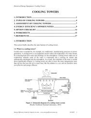
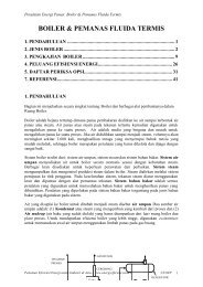
A faster way to calculate the excess air is by using the figures 2 <strong>and</strong> 3, provided the<br />
percentage of CO2 or O2 in the flue gases have been measured.<br />
Figure 2. Relation between CO 2 & Excess Air<br />
(Bureau of Energy Efficiency, 2004)<br />
Figure 3. Relationship between residual oxygen <strong>and</strong> excess air<br />
(Bureau of Energy Efficiency, 2004)<br />
Energy Efficiency Guide for Industry in Asia – www.energyefficiencyasia.org ©UNEP 16
Thermal Equipment: <strong>Fuels</strong> <strong>and</strong> <strong>Combustion</strong><br />
For optimum combustion of fuel oil the CO2 or O2 in flue gases should be maintained as<br />
follows:<br />
CO2 = 14.5–15 %<br />
O2 = 2–3 %<br />
3.4 Draft System<br />
The function of draft in a combustion system is to exhaust the products of combustion, i.e.<br />
flue gases, into the atmosphere. The draft can be classified into two types namely natural<br />
draft <strong>and</strong> mechanical draft.<br />
3.4.1 Natural draft<br />
Natural draft is the draft produced by a chimney alone. It is caused by the difference in<br />
weight between the column of hot gas inside the chimney <strong>and</strong> column of outside air of the<br />
same height <strong>and</strong> cross section. Being much lighter than outside air, chimney flue gas tends to<br />
rise, <strong>and</strong> the heavier outside air flows in through the ash pit to take its place. Draft is usually<br />
controlled by h<strong>and</strong>-operated dampers in the chimney <strong>and</strong> breeching connecting the boiler to<br />
the chimney. Here no fans or blowers are used. The products of combustion are discharged at<br />
such a height that it will not be a nuisance to the surrounding community.<br />
3.4.2 Mechanical draft<br />
It is draft artificially produced by fans. Three basic types of drafts that are applied are:<br />
• Balanced draft: Forced-draft (F-D) fan (blower) pushes air into the furnace <strong>and</strong> an<br />
induced draft (I-D) fan draws gases into the chimney thereby providing draft to remove<br />
the gases from the boiler. Here the pressure is maintained between 0.05 to 0.10 in. of<br />
water gauge below atmospheric pressure in the case of boilers <strong>and</strong> slightly positive for<br />
reheating <strong>and</strong> heat treatment furnaces.<br />
• Induced draft: An induced-draft fan draws enough draft for flow into the furnace,<br />
causing the products of combustion to discharge to atmosphere. Here the furnace is kept<br />
at a slight negative pressure below the atmospheric pressure so that combustion air flows<br />
through the system.<br />
• Forced draft: The Forced draft system uses a fan to deliver the air to the furnace, forcing<br />
combustion products to flow through the unit <strong>and</strong> up the stack.<br />
4. ENERGY EFFICIENCY OPPORTUNITIES<br />
This section includes energy efficiency opportunities in Fuel <strong>Combustion</strong><br />
4.1 Pre-heating of the <strong>Combustion</strong> Oil<br />
The viscosity of furnace oil <strong>and</strong> LSHS (Low Sulphur Heavy Stock) increases with decreasing<br />
temperature, which makes it difficult to pump the oil. At low ambient temperatures (below 25<br />
0 C), furnace oil cannot be pumped easily. To circumvent this, preheating of oil is<br />
accomplished in two ways:<br />
• The entire tank may be preheated. In this form of bulk heating, steam coils are placed at<br />
the bottom of the tank, which is fully insulated;<br />
Energy Efficiency Guide for Industry in Asia – www.energyefficiencyasia.org ©UNEP 17
Thermal Equipment: <strong>Fuels</strong> <strong>and</strong> <strong>Combustion</strong><br />
• The oil can be heated as it flows out with an outflow heater. To reduce steam<br />
requirements, it is advisable to insulate tanks where bulk heating is used.<br />
Bulk heating may be necessary if flow rates are high enough to make outflow heaters of<br />
adequate capacity impractical, or when a fuel such as LSHS is used. In the case of outflow<br />
heating, only the oil, which leaves the tank, is heated to the pumping temperature. The<br />
outflow heater is essentially a heat exchanger with steam or electricity as the heating<br />
medium.<br />
4.2 Temperature control of <strong>Combustion</strong> Oil<br />
Thermostatic temperature control of the oil is necessary to prevent overheating, especially<br />
when oil flow is reduced or stopped. This is particularly important for electric heaters, since<br />
oil may get carbonized when there is no flow <strong>and</strong> the heater is on. Thermostats should be<br />
provided at a region where the oil flows freely into the suction pipe. The temperature at<br />
which oil can readily be pumped depends on the grade of oil being h<strong>and</strong>led. Oil should never<br />
be stored at a temperature above that necessary for pumping as this leads to higher energy<br />
consumption.<br />
4.3 Preparation of Solid <strong>Fuels</strong><br />
4.3.1 Sizing of coal<br />
Proper coal sizing is one of the key measures to ensure efficient combustion. Proper coal<br />
sizing, with specific relevance to the type of firing system, helps towards even burning,<br />
reduced ash losses <strong>and</strong> better combustion efficiency.<br />
Coal is reduced in size by crushing <strong>and</strong> pulverizing. Pre-crushed coal can be economical for<br />
smaller units, especially stoker-fired units. In a coal h<strong>and</strong>ling system, crushing is limited to<br />
an upper size of 6 or 4mm. The devices most commonly used for crushing are the rotary<br />
breaker, the roll crusher <strong>and</strong> the hammer mill.<br />
It is necessary to screen the coal before crushing, so that only oversized coal is fed to the<br />
crusher. This helps to reduce power consumption in the crusher. Recommended practices in<br />
coal crushing are:<br />
• Incorporation of a screen to separate fines <strong>and</strong> small particles to avoid extra fine<br />
generation in crushing.<br />
• Incorporation of a magnetic separator to separate iron pieces in coal, which may damage<br />
the crusher.<br />
Table 11 gives the proper size of coal for various types of firing systems.<br />
Table 11. Proper size of coal for various types of firing system<br />
No. Types of Firing System Size (in mm)<br />
1. H<strong>and</strong> Firing<br />
(a) Natural draft 25-75<br />
(b) Forced draft 25-40<br />
Energy Efficiency Guide for Industry in Asia – www.energyefficiencyasia.org ©UNEP 18
Thermal Equipment: <strong>Fuels</strong> <strong>and</strong> <strong>Combustion</strong><br />
4.3.2 Conditioning of coal<br />
2. Stoker Firing<br />
(a) Chain grate<br />
i) Natural draft<br />
ii) Forced draft<br />
(b) Spreader Stoker<br />
25-40<br />
15-25<br />
15-25<br />
3. Pulverized Fuel Fired 75% below 75 micron*<br />
4 Fluidized bed boiler < 10 mm<br />
*1 Micron = 1/1000 mm<br />
The fines in coal present problems in combustion on account of segregation effects.<br />
Segregation of fines from larger coal pieces can be reduced to a great extent by conditioning<br />
coal with water. Water helps fine particles to stick to the bigger lumps due to surface tension<br />
of the moisture, thus stopping fines from falling through grate bars or being carried away by<br />
the furnace draft. While tempering the coal, care should be taken to ensure that moisture<br />
addition is uniform <strong>and</strong> preferably done in a moving or falling stream of coal.<br />
If the percentage of fines in the coal is very high, wetting of coal can decrease the percentage<br />
of unburnt carbon <strong>and</strong> the excess air level required for combustion. The table below shows<br />
the extent of wetting, depending on the percentage of fines in coal.<br />
Table 12. Extent of wetting: fines vs surface moisture in coal<br />
Fines (%) Surface Moisture (%)<br />
10 - 15 4 - 5<br />
15 - 20 5 - 6<br />
20 - 25 6 - 7<br />
25 - 30 7 - 8<br />
4.3.3 Blending of coal<br />
In the case of coal containing excessive fines, it is advisable to blend the predominantly<br />
lumped coal with lot of coal that contains excessive fines. Coal blending may thus help to<br />
limit the extent of fines in coal being fired to not more than 25%. Blending of different<br />
qualities of coal may also help to supply a uniform coal feed to the boiler.<br />
4.4 <strong>Combustion</strong> Controls<br />
<strong>Combustion</strong> controls assist the burner in regulation of fuel supply, air supply, (fuel to air<br />
ratio), <strong>and</strong> removal of gases of combustion to achieve optimum boiler efficiency. The amount<br />
of fuel supplied to the burner must be in proportion to the steam pressure <strong>and</strong> the quantity of<br />
steam required. The combustion controls are also necessary as safety device to ensure that<br />
the boiler operates safely.<br />
Various types of combustion controls in use are:<br />
• On/Off control: The simplest control, ON/OFF control means that either the burner is<br />
firing at full rate or it is OFF. This type of control is limited to small boilers.<br />
• High/low/off control: Slightly more complex is HIGH/LOW/OFF system where the<br />
burner has two firing rates. The burner operates at slower firing rate <strong>and</strong> then switches to<br />
Energy Efficiency Guide for Industry in Asia – www.energyefficiencyasia.org ©UNEP 19
Thermal Equipment: <strong>Fuels</strong> <strong>and</strong> <strong>Combustion</strong><br />
full firing as needed. Burners can also revert to the low firing position at reduced load.<br />
This control is fitted to medium sized boilers.<br />
• Modulating control: The modulating control operates on the principle of matching the<br />
steam pressure dem<strong>and</strong> by altering the firing rate over the entire operating range of the<br />
boiler. Modulating motors use conventional mechanical linkage or electric valves to<br />
regulate the primary air, secondary air, <strong>and</strong> fuel supplied to the burner. Full modulation<br />
means that boiler keeps firing, <strong>and</strong> fuel <strong>and</strong> air are carefully matched over the whole<br />
firing range to maximize thermal efficiency.<br />
5. OPTION CHECKLIST<br />
This section includes most important options to improve energy efficiency of fuel use <strong>and</strong> in<br />
combustion processes.<br />
Fuel Checklist<br />
• Daily check: Oil temperature at the burner <strong>and</strong> oil/steam leakages<br />
• Weekly task: Cleaning of all filters <strong>and</strong> draining of water from all tanks<br />
• Yearly task: Cleaning of all tanks<br />
Troubleshooting for fuels<br />
1. Oil not pumpable<br />
• Viscosity too high<br />
• Blocked lines <strong>and</strong> filters<br />
• Sludge in oil<br />
• Leak in oil suction<br />
• Vent pipe choked<br />
2. Blocking of strainers<br />
• Sludge or wax in oil<br />
• Heavy precipitated compounds in oil<br />
• Rust or scale in tank<br />
• Carbonization of oil due to excessive heating<br />
3. Excess water in oil<br />
• Water delivered along with oil<br />
• Leaking manhole<br />
• Seepage from underground tank<br />
• Ingress of moisture from vent pipe<br />
• Leaking heater steam coils<br />
4. Pipeline plugged<br />
• Sludge in oil<br />
• High viscosity oil<br />
• Foreign materials such as rags, scale <strong>and</strong> wood splinters in line<br />
• Carbonization of oil<br />
Energy Efficiency Guide for Industry in Asia – www.energyefficiencyasia.org ©UNEP 20
Thermal Equipment: <strong>Fuels</strong> <strong>and</strong> <strong>Combustion</strong><br />
<strong>Combustion</strong> Checklist<br />
1. Start up<br />
• Check for correct sized burner/nozzle.<br />
• Establish air supply first (start blower). Ensure no vapour/gases are present before<br />
light up.<br />
• Ensure a flame from a torch or other source is placed in front of the nozzle.<br />
• Turn ON the (preheated) oil supply (before start-up, drain off cold oil).<br />
2. Operations<br />
• Check for correct temperature of oil at the burner tip (consult viscosity vs.<br />
temperature chart).<br />
• Check air pressure for LAP burners (63.5 cm to 76.2 cm w.c. air pressure is<br />
commonly adopted).<br />
• Check for oil drips near burner.<br />
• Check for flame fading/flame pulsation.<br />
• Check positioning of burner (ensure no flame impingement on refractory walls or<br />
charge).<br />
• Adjust flame length to suit the conditions (ensure flame does not extend beyond the<br />
furnace).<br />
3. Load changes<br />
• Operate both air <strong>and</strong> oil valves simultaneously (For self-proportioned burner, operate<br />
the self-proportioning lever. Do not adjust valve only in oil line).<br />
• Adjust burners <strong>and</strong> damper for a light brown (hazy) smoke from chimney <strong>and</strong> at least<br />
12 percent CO2.<br />
4. Shut down<br />
• Close oil line first.<br />
• Shut the blower after a few seconds (ensure gases are purged from combustion<br />
chamber).<br />
• Do not expose the burner nozzle to the radiant heat of the furnace. (When oil is shut<br />
off, remove burner/nozzle or interpose a thin refractory between nozzle <strong>and</strong> furnace).<br />
Troubleshooting for combustion<br />
The checklist in the Table below can help find the causes <strong>and</strong> solutions for typical problems<br />
found with fuel combustion.<br />
Energy Efficiency Guide for Industry in Asia – www.energyefficiencyasia.org ©UNEP 21
Thermal Equipment: <strong>Fuels</strong> <strong>and</strong> <strong>Combustion</strong><br />
TROUBLESHOOTING CHART FOR COMBUSTION<br />
No Problems Causes & solutions<br />
1. Starting difficult 1. No oil in the tank.<br />
2. Excess sludge <strong>and</strong> water in storage tanks.<br />
3. Oil not flowing due to high viscosity/low temperature.<br />
4. Choked burner tip.<br />
5. No air.<br />
6. Strainers choked.<br />
2. Flame goes out or<br />
splutters<br />
1. Sludge or water in oil.<br />
2. Unsteady oil <strong>and</strong> air pressures.<br />
3. Too high a pressure for atomizing medium which tends to blow<br />
out flame.<br />
4. Presence of air in oil line. Look for leakages in suction line of<br />
pump.<br />
5. Broken burner block, or burner without block.<br />
3. Flame flashes back 1. Oil supply left in ‘ON’position after air supply cut off during<br />
earlier shut off.<br />
2. Too high a positive pressure in combustion chamber.<br />
3. Furnace too cold during starting to complete combustion (when<br />
temperature rises, unburned oil particles burn).<br />
4. Oil pressure too low.<br />
4 Smoke <strong>and</strong> soot 1. Insufficient draft or blower of inadequate<br />
2. Oil flow excessive.<br />
3. Oil too heavy <strong>and</strong> not preheated to<br />
4. Suction air holes in blower plugged.<br />
5. Chimney clogged with soot/damper<br />
6. Blower operating speed too low.<br />
5. Clinker on refractory 1. Flame hits refractory because combustion chamber is too small<br />
or<br />
2. is not correctly aligned.<br />
3. Oil dripping from nozzle.<br />
4. Oil supply not ’cut off’before the air supply during shut-offs.<br />
6. Cooking of fuel in<br />
burner<br />
7. Excessive fuel oil<br />
consumption<br />
1. Nozzle exposed to furnace radiation after shut-<br />
2. Burner fed with atomizing air over 300 °C.<br />
3. Burner block too short or too wide.<br />
4. Oil not drained from nozzle after shut off.<br />
1. Improper ratio of oil <strong>and</strong> air.<br />
2. Burner nozzle oversized.<br />
3. Excessive draft.<br />
4. Improper oil/air mixing by burner.<br />
5. Air <strong>and</strong> oil pressure not correct<br />
6. Oil not preheated properly.<br />
7. Oil viscosity too low for the type of burner used.<br />
8. Oil leaks in oil pipelines/preheater.<br />
9. Bad maintenance (too high or rising stack gas temperature).<br />
Energy Efficiency Guide for Industry in Asia – www.energyefficiencyasia.org ©UNEP 22
Thermal Equipment: <strong>Fuels</strong> <strong>and</strong> <strong>Combustion</strong><br />
6. WORKSHEETS<br />
Worksheet 1: Excess Air Calculation<br />
No Parameters Formula Units Value<br />
1 Carbon (C) % by Weight<br />
2 Hydrogen (H) % by Weight<br />
3 Oxygen (O 4 ) % by Weight<br />
4 Nitrogen % by Weight<br />
5 Sulphur % by Weight<br />
6 H 2 O % by Weight<br />
7 Ash % by Weight<br />
8 GCV of Fuel kCal/kg<br />
9 Oxygen Required for C x (32/12) kg/100 kg of Fuel<br />
burning of Carbon (O 1 )<br />
10 Oxygen Required for<br />
H x (32/4) kg/100 kg of Fuel<br />
burning of Hydrogen (O 2 )<br />
11 Oxygen Required for S x (32/32) kg/100 kg of Fuel<br />
burning of Sulphur (O 3 )<br />
12 Total Oxygen Required O 1 + O 2 + O 3 –O 4 kg/100 kg of Fuel<br />
(O)<br />
13 Stochiometric Amount of O / 0.23 kg/100 kg of Fuel<br />
Air Required (S.A)<br />
14 Excess Air (EA) %<br />
15 Actual Amount of Air<br />
Required<br />
S.A x (1+ EA/100) kg/100 kg of Fuel<br />
Energy Efficiency Guide for Industry in Asia – www.energyefficiencyasia.org ©UNEP 23
Thermal Equipment: <strong>Fuels</strong> <strong>and</strong> <strong>Combustion</strong><br />
7. REFERENCES<br />
Bureau of Energy Efficiency. Energy Efficiency in Thermal Utilities. <strong>Chapter</strong> 1. 2004<br />
Department of Coal, Government of India. Coal <strong>and</strong> Cement Industry –Efficient utilization.<br />
1985<br />
Department of Coal, Government of India. Coal <strong>and</strong> Furnace Operation –Improved<br />
techniques. 1985<br />
Department of Coal, Government of India. Coal <strong>and</strong> Industrial Furnaces –Efficient<br />
utilization. 1985<br />
Department of Coal, Government of India. Coal <strong>and</strong> Pulp <strong>and</strong> Paper industry –Efficient<br />
utilization. 1985<br />
Department of Coal, Government of India. Coal <strong>and</strong> Textile Industry –Efficient utilization.<br />
1985<br />
Department of Coal, Government of India. Coal <strong>Combustion</strong> –Improved techniques for<br />
efficiency. 1985<br />
Department of Coal, Government of India. Fluidised Bed Coal Fired Boilers. 1985<br />
Petroleum Conservation Research Association. www.pcra.org<br />
Shaha, A.K. <strong>Combustion</strong> Engineering <strong>and</strong> Fuel Technology. Oxford & IBH Publishing<br />
Company<br />
Thermax India Ltd. Technical Memento<br />
Copyright:<br />
Copyright © United Nations Environment Programme (year 2006)<br />
This publication may be reproduced in whole or in part <strong>and</strong> in any form for educational or non-profit purposes without<br />
special permission from the copyright holder, provided acknowledgement of the source is made. UNEP would appreciate<br />
receiving a copy of any publication that uses this publication as a source. No use of this publication may be made for resale<br />
or any other commercial purpose whatsoever without prior permission from the United Nations Environment Programme.<br />
Disclaimer:<br />
This energy equipment module was prepared as part of the project “Greenhouse Gas Emission Reduction from Industry in<br />
Asia <strong>and</strong> the Pacific” (GERIAP) by the National Productivity Council, India. While reasonable efforts have been made to<br />
ensure that the contents of this publication are factually correct <strong>and</strong> properly referenced, UNEP does not accept<br />
responsibility for the accuracy or completeness of the contents, <strong>and</strong> shall not be liable for any loss or damage that may be<br />
occasioned directly or indirectly through the use of, or reliance on, the contents of this publication.<br />
Energy Efficiency Guide for Industry in Asia – www.energyefficiencyasia.org ©UNEP 24