Chapter – Cooling Towers - RETScreen International
Chapter – Cooling Towers - RETScreen International
Chapter – Cooling Towers - RETScreen International

You also want an ePaper? Increase the reach of your titles
YUMPU automatically turns print PDFs into web optimized ePapers that Google loves.
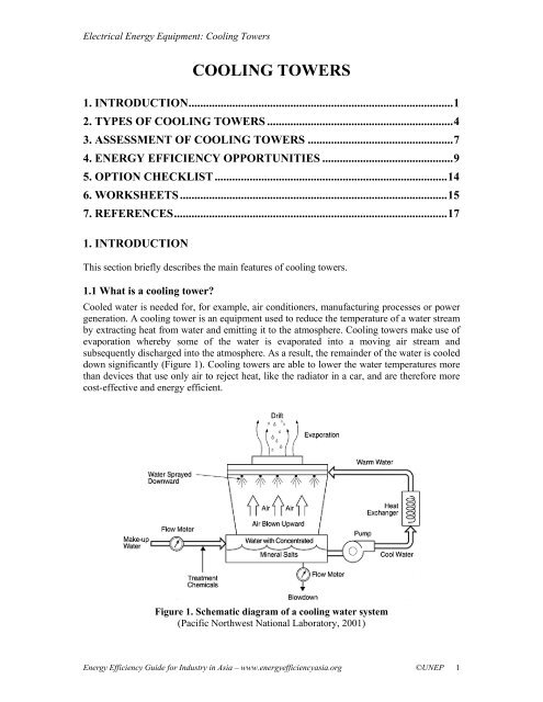
Electrical Energy Equipment: <strong>Cooling</strong> <strong>Towers</strong>COOLING TOWERS1. INTRODUCTION...........................................................................................12. TYPES OF COOLING TOWERS ................................................................43. ASSESSMENT OF COOLING TOWERS ..................................................74. ENERGY EFFICIENCY OPPORTUNITIES .............................................95. OPTION CHECKLIST ................................................................................146. WORKSHEETS............................................................................................157. REFERENCES..............................................................................................171. INTRODUCTIONThis section briefly describes the main features of cooling towers.1.1 What is a cooling tower?Cooled water is needed for, for example, air conditioners, manufacturing processes or powergeneration. A cooling tower is an equipment used to reduce the temperature of a water streamby extracting heat from water and emitting it to the atmosphere. <strong>Cooling</strong> towers make use ofevaporation whereby some of the water is evaporated into a moving air stream andsubsequently discharged into the atmosphere. As a result, the remainder of the water is cooleddown significantly (Figure 1). <strong>Cooling</strong> towers are able to lower the water temperatures morethan devices that use only air to reject heat, like the radiator in a car, and are therefore morecost-effective and energy efficient.Figure 1. Schematic diagram of a cooling water system(Pacific Northwest National Laboratory, 2001)Energy Efficiency Guide for Industry in Asia <strong>–</strong> www.energyefficiencyasia.org ©UNEP 1
Electrical Energy Equipment: <strong>Cooling</strong> <strong>Towers</strong>1.2 Components of a cooling towerThe basic components of a cooling tower include the frame and casing, fill, cold-water basin,drift eliminators, air inlet, louvers, nozzles and fans. These are described below. 1Frame and casing. Most towers have structural frames that support the exterior enclosures(casings), motors, fans, and other components. With some smaller designs, such as someglass fiber units, the casing may essentially be the frame.Fill. Most towers employ fills (made of plastic or wood) to facilitate heat transfer bymaximizing water and air contact. There are two types of fill:• Splash fill: water falls over successive layers of horizontal splash bars, continuouslybreaking into smaller droplets, while also wetting the fill surface. Plastic splash fillspromote better heat transfer than wood splash fills.• Film fill: consists of thin, closely spaced plastic surfaces over which the water spreads,forming a thin film in contact with the air. These surfaces may be flat, corrugated,honeycombed, or other patterns. The film type of fill is the more efficient and providessame heat transfer in a smaller volume than the splash fill.Cold-water basin. The cold-water basin is located at or near the bottom of the tower, and itreceives the cooled water that flows down through the tower and fill. The basin usually has asump or low point for the cold-water discharge connection. In many tower designs, the coldwaterbasin is beneath the entire fill. In some forced draft counter flow design, however, thewater at the bottom of the fill is channeled to a perimeter trough that functions as the coldwaterbasin. Propeller fans are mounted beneath the fill to blow the air up through the tower.With this design, the tower is mounted on legs, providing easy access to the fans and theirmotors.Drift eliminators. These capture water droplets entrapped in the air stream that otherwisewould be lost to the atmosphere.Air inlet. This is the point of entry for the air entering a tower. The inlet may take up anentire side of a tower (cross-flow design) or be located low on the side or the bottom of thetower (counter-flow design).Louvers. Generally, cross-flow towers have inlet louvers. The purpose of louvers is toequalize air flow into the fill and retain the water within the tower. Many counter flow towerdesigns do not require louvers.Nozzles. These spray water to wet the fill. Uniform water distribution at the top of the fill isessential to achieve proper wetting of the entire fill surface. Nozzles can either be fixed andspray in a round or square patterns, or they can be part of a rotating assembly as found insome circular cross-section towers.Fans. Both axial (propeller type) and centrifugal fans are used in towers. Generally, propellerfans are used in induced draft towers and both propeller and centrifugal fans are found inforced draft towers. Depending upon their size, the type of propeller fans used is either fixed1 Section 1.2 is taken in its entirety from <strong>Cooling</strong> <strong>Towers</strong>. In: Energy Efficiency in Electrical Utilities. <strong>Chapter</strong> 7, pg 135 -151. 2004, with the permission from Bureau of Energy Efficiency, Ministry of Power, IndiaEnergy Efficiency Guide for Industry in Asia <strong>–</strong> www.energyefficiencyasia.org ©UNEP 2
Electrical Energy Equipment: <strong>Cooling</strong> <strong>Towers</strong>or variable pitch. A fan with non-automatic adjustable pitch blades can be used over a widekW range because the fan can be adjusted to deliver the desired air flow at the lowest powerconsumption. Automatic variable pitch blades can vary air flow in response to changing loadconditions.1.3 Tower materialsOriginally, cooling towers were constructed primarily with wood, including the frame,casing, louvers, fill and cold-water basin. Sometimes the cold-water basin was made ofconcrete. Today, manufacturers use a variety of materials to construct cooling towers.Materials are chosen to enhance corrosion resistance, reduce maintenance, and promotereliability and long service life. Galvanized steel, various grades of stainless steel, glass fiber,and concrete are widely used in tower construction, as well as aluminum and plastics forsome components. 2Frame and casing. Wooden towers are still available, but many components are made ofdifferent materials, such as the casing around the wooden framework of glass fiber, the inletair louvers of glass fiber, the fill of plastic and the cold-water basin of steel. Many towers(casings and basins) are constructed of galvanized steel or, where a corrosive atmosphere is aproblem, the tower and/or the basis are made of stainless steel. Larger towers sometimes aremade of concrete. Glass fiber is also widely used for cooling tower casings and basins,because they extend the life of the cooling tower and provide protection against harmfulchemicals.Fill. Plastics are widely used for fill, including PVC, polypropylene, and other polymers.When water conditions require the use of splash fill, treated wood splash fill is still used inwooden towers, but plastic splash fill is also widely used. Because of greater heat transferefficiency, film fill is chosen for applications where the circulating water is generally free ofdebris that could block the fill passageways.Nozzles. Plastics are also widely used for nozzles. Many nozzles are made of PVC, ABS,polypropylene, and glass-filled nylon.Fans. Aluminum, glass fiber and hot-dipped galvanized steel are commonly used fanmaterials. Centrifugal fans are often fabricated from galvanized steel. Propeller fans are madefrom galvanized steel, aluminum, or molded glass fiber reinforced plastic.2 Section 1.3 is taken from <strong>Cooling</strong> <strong>Towers</strong>. In: Energy Efficiency in Electrical Utilities. <strong>Chapter</strong> 7, pg 135 - 151. 2004, withthe permission from Bureau of Energy Efficiency, Ministry of Power, IndiaEnergy Efficiency Guide for Industry in Asia <strong>–</strong> www.energyefficiencyasia.org ©UNEP 3
Electrical Energy Equipment: <strong>Cooling</strong> <strong>Towers</strong>2. TYPES OF COOLING TOWERSThis section describes the two main types of cooling towers: the natural draft and mechanicaldraft cooling towers.2.1 Natural draft cooling towerThe natural draft or hyperbolic cooling tower makes use of the difference in temperaturebetween the ambient air and the hotter air inside the tower. As hot air moves upwards throughthe tower (because hot air rises), fresh cool air is drawn into the tower through an air inlet atthe bottom. Due to the layout of the tower, no fan is required and there is almost nocirculation of hot air that could affect the performance. Concrete is used for the tower shellwith a height of up to 200 m. These cooling towers are mostly only for large heat dutiesbecause large concrete structures are expensive.Figure 2. Cross flow natural draft cooling towerFigure 3. Counter flow natural draft cooling tower(Gulf Coast Chemical Commercial Inc, 1995)There are two main types of natural draft towers:• Cross flow tower (Figure 2): air is drawn across the falling water and the fill is locatedoutside the tower• Counter flow tower (Figure 3): air is drawn up through the falling water and the fill istherefore located inside the tower, although design depends on specific site conditions2.2 Mechanical draft cooling towerMechanical draft towers have large fans to force or draw air through circulated water. Thewater falls downwards over fill surfaces, which help increase the contact time between thewater and the air - this helps maximize heat transfer between the two. <strong>Cooling</strong> rates ofmechanical draft towers depend upon various parameters such as fan diameter and speed ofoperation, fills for system resistance etc.Energy Efficiency Guide for Industry in Asia <strong>–</strong> www.energyefficiencyasia.org ©UNEP 4
Electrical Energy Equipment: <strong>Cooling</strong> <strong>Towers</strong>Mechanical draft towers are available in a large range of capacities. <strong>Towers</strong> can be eitherfactory built or field erected <strong>–</strong> for example concrete towers are only field erected.Many towers are constructed so that they can be grouped together to achieve the desiredcapacity. Thus, many cooling towers are assemblies of two or more individual cooling towersor “cells.” The number of cells they have, e.g., a eight-cell tower, often refers to such towers.Multiple-cell towers can be lineal, square, or round depending upon the shape of theindividual cells and whether the air inlets are located on the sides or bottoms of the cells.The three types of mechanical draft towers are summarized in Table 1.Table 1. Main features of different types of draft cooling towers (based on AIRAH)Type of cooling tower Advantages DisadvantagesForced draft cooling tower (Figure 4): air isblown through the tower by a fan located inthe air inletInduced draft cross flow cooling tower(Figure 5):• water enters at top and passes over fill• air enters on one side (single-flow tower)or opposite sides (double-flow tower)• an induced draft fan draws air across filltowards exit at top of towerInduced draft counter flow cooling tower(Figure 6):• hot water enters at the top• air enters bottom and exits at the top• uses forced and induced draft fans• Suited for high airresistance due tocentrifugal blowerfans• Fans are relativelyquiet• Less recirculationthan forced drafttowers because thespeed of exit air is3-4 times higherthan entering air• Recirculation due to highair-entry and low air-exitvelocities, which can besolved by locating towersin plant rooms combinedwith discharge ducts• Fans and the motor drivemechanism requireweather-proofing againstmoisture and corrosionbecause they are in thepath of humid exit airFigure 4. Forced Draft <strong>Cooling</strong> Tower ((GEO4VA))Energy Efficiency Guide for Industry in Asia <strong>–</strong> www.energyefficiencyasia.org ©UNEP 5
Electrical Energy Equipment: <strong>Cooling</strong> <strong>Towers</strong>Figure 5. Induced draft counter flow cooling tower(GEO4VA)Figure 6. Induced draft cross flow cooling tower(GEO4VA)Energy Efficiency Guide for Industry in Asia <strong>–</strong> www.energyefficiencyasia.org ©UNEP 6
Electrical Energy Equipment: <strong>Cooling</strong> <strong>Towers</strong>3. ASSESSMENT OF COOLING TOWERSThis section describes how the performance of cooling powers can be assessed. 3 Theperformance of cooling towers is evaluated to assess present levels of approach and rangeagainst their design values, identify areas of energy wastage and to suggest improvements.During the performance evaluation, portable monitoring instruments are used to measure thefollowing parameters:• Wet bulb temperature of air• Dry bulb temperature of air• <strong>Cooling</strong> tower inlet water temperature• <strong>Cooling</strong> tower outlet water temperature• Exhaust air temperature• Electrical readings of pump and fan motors• Water flow rate• Air flow rateHot Water Temperature (In)Range(In) to the Tower(Out) from the TowerCold-water Temperature (Out)ApproachWet Bulb Temperature (Ambient)Figure 7. Range and approach of cooling towersThese measured parameters and then used to determine the cooling tower performance inseveral ways. (Note: CT = cooling tower; CW = cooling water). These are:a) Range (see Figure 7). This is the difference between the cooling tower water inlet andoutlet temperature. A high CT Range means that the cooling tower has been able toreduce the water temperature effectively, and is thus performing well. The formula is:CT Range (°C) = [CW inlet temp (°C) <strong>–</strong> CW outlet temp (°C)]3 Section 1.2 is based on <strong>Cooling</strong> <strong>Towers</strong>. In: Energy Efficiency in Electrical Utilities. <strong>Chapter</strong> 7, pg 135 - 151. 2004, withthe permission from Bureau of Energy Efficiency, Ministry of Power, IndiaEnergy Efficiency Guide for Industry in Asia <strong>–</strong> www.energyefficiencyasia.org ©UNEP 7
Electrical Energy Equipment: <strong>Cooling</strong> <strong>Towers</strong>b) Approach (see Figure 7). This is the difference between the cooling tower outlet coldwatertemperature and ambient wet bulb temperature. The lower the approach the betterthe cooling tower performance. Although, both range and approach should be monitored,the `Approach’ is a better indicator of cooling tower performance.CT Approach (°C) = [CW outlet temp (°C) <strong>–</strong> Wet bulb temp (°C)]c) Effectiveness. This is the ratio between the range and the ideal range (in percentage), i.e.difference between cooling water inlet temperature and ambient wet bulb temperature, orin other words it is = Range / (Range + Approach). The higher this ratio, the higher thecooling tower effectiveness.CT Effectiveness (%) = 100 x (CW temp <strong>–</strong> CW out temp) / (CW in temp <strong>–</strong> WB temp)d) <strong>Cooling</strong> capacity. This is the heat rejected in kCal/hr or TR, given as product of massflow rate of water, specific heat and temperature difference.e) Evaporation loss. This is the water quantity evaporated for cooling duty. Theoreticallythe evaporation quantity works out to 1.8 m 3 for every 1,000,000 kCal heat rejected. Thefollowing formula can be used (Perry):Evaporation loss (m 3 /hr) = 0.00085 x 1.8 x circulation rate (m 3 /hr) x (T1-T2)T1 - T2 = temperature difference between inlet and outlet waterf) Cycles of concentration (C.O.C). This is the ratio of dissolved solids in circulating waterto the dissolved solids in make up water.g) Blow down losses depend upon cycles of concentration and the evaporation losses and isgiven by formula:Blow down = Evaporation loss / (C.O.C. <strong>–</strong> 1)h) Liquid/Gas (L/G) ratio. The L/G ratio of a cooling tower is the ratio between the waterand the air mass flow rates. <strong>Cooling</strong> towers have certain design values, but seasonalvariations require adjustment and tuning of water and air flow rates to get the best coolingtower effectiveness. Adjustments can be made by water box loading changes or bladeangle adjustments. Thermodynamic rules also dictate that the heat removed from thewater must be equal to the heat absorbed by the surrounding air. Therefore the followingformulae can be used:L(T1 <strong>–</strong> T2) = G(h2 <strong>–</strong> h1)L/G = (h2 <strong>–</strong> h1) / (T1 <strong>–</strong> T2)Where:L/G = liquid to gas mass flow ratio (kg/kg)T1 = hot water temperature ( 0 C)T2 = cold-water temperature ( 0 C)Energy Efficiency Guide for Industry in Asia <strong>–</strong> www.energyefficiencyasia.org ©UNEP 8
Electrical Energy Equipment: <strong>Cooling</strong> <strong>Towers</strong>h2 = enthalpy of air-water vapor mixture at exhaust wet-bulb temperature (same unitsas above)h1 = enthalpy of air-water vapor mixture at inlet wet-bulb temperature (sameunits as above)4. ENERGY EFFICIENCY OPPORTUNITIESThis section includes main areas for improving energy efficiency of cooling towers. The mainareas for energy conservation include: 4• Selecting the right cooling tower (because the structural aspects of the cooling towercannot be changed after it is installed)• Fills• Pumps and water distribution system• Fans and motors4.1 Selecting the right cooling towersOnce a cooling tower is in place it is very difficult to significantly improve its energyperformance. A number of factors are of influence on the cooling tower’s performance andshould be considered when choosing a cooling tower: capacity, range, approach, heat load,wet bulb temperature, and the relationship between these factors. This is described below.4.1.1 CapacityHeat dissipation (in kCal/hour) and circulated flow rate (m 3 /hr) are an indication of thecapacity of cooling towers. However, these design parameters are not sufficient to understandthe cooling tower performance. For example, a cooling tower sized to cool 4540 m 3 /hrthrough a 13.9 0 C range might be larger than a cooling tower to cool 4540 m 3 /hr through 19.50 C range. Therefore other design parameters are also needed.4.1.2 RangeRange is determined not by the cooling tower, but by the process it is serving. The range atthe exchanger is determined entirely by the heat load and the water circulation rate throughthe exchanger and going to the cooling water. The range is a function of the heat load and theflow circulated through the system:Range 0 C = Heat load (in kCal/hour) / Water circulation rate (l/hour)<strong>Cooling</strong> towers are usually specified to cool a certain flow rate from one temperature toanother temperature at a certain wet bulb temperature. For example, the cooling tower mightbe specified to cool 4540 m 3 /hr from 48.9 o C to 32.2 o C at 26.7 o C wet bulb temperature.4.1.3 ApproachAs a general rule, the closer the approach to the wet bulb, the more expensive the coolingtower due to increased size. Usually a 2.8 o C approach to the design wet bulb is the coldestwater temperature that cooling tower manufacturers will guarantee. When the size of the4 Section 1.2 is based on <strong>Cooling</strong> <strong>Towers</strong>. In: Energy Efficiency in Electrical Utilities. <strong>Chapter</strong> 7, pg 135 - 151. 2004, withthe permission from Bureau of Energy Efficiency, Ministry of Power, IndiaEnergy Efficiency Guide for Industry in Asia <strong>–</strong> www.energyefficiencyasia.org ©UNEP 9
Electrical Energy Equipment: <strong>Cooling</strong> <strong>Towers</strong>tower has to be chosen, then the approach is most important, closely followed by the flowrate, and the range and wet bulb would be of lesser importance.Approach (5.5 0 C) = Cold-water temperature 32.2 0 C <strong>–</strong> Wet bulb temperature (26.70 C)4.1.4 Heat loadThe heat load imposed on a cooling tower is determined by the process being served. Thedegree of cooling required is controlled by the desired operating temperature of the process.In most cases, a low operating temperature is desirable to increase process efficiency or toimprove the quality or quantity of the product. However, in some applications (e.g. internalcombustion engines) high operating temperatures are desirable. The size and cost of thecooling tower is increases with increasing heat load. Purchasing undersized equipment (if thecalculated heat load is too low) and oversized equipment (if the calculated heat load is toohigh) is something to be aware of.Process heat loads may vary considerably depending upon the process involved and aretherefore difficult to determine accurately. On the other hand, air conditioning andrefrigeration heat loads can be determined with greater accuracy.Information is available for the heat rejection requirements of various types of powerequipment. A sample list is as follows (BEE, 2004):• Air Compressor- Single-stage - 129 kCal/kW/hr- Single-stage with after cooler - 862 kCal/kW/hr- Two-stage with intercooler - 518 kCal/kW/hr- Two-stage with intercooler and after cooler - 862 kCal/kW/hr• Refrigeration, Compression - 63 kCal/min/TR• Refrigeration, Absorption - 127 kCal/min/TR• Steam Turbine Condenser - 555 kCal/kg of steam• Diesel Engine, Four-Cycle, Supercharged - 880 kCal/kW/hr• Natural Gas Engine, Four-cycle - 1523 kCal/kW/hr (= 18 kg/cm 2 compression)4.1.5 Wet bulb temperatureWet bulb temperature is an important factor in performance of evaporative water coolingequipment, because it is the lowest temperature to which water can be cooled. For this reason,the wet bulb temperature of the air entering the cooling tower determines the minimumoperating temperature level throughout the plant, process, or system. The following should beconsidered when pre-selecting a cooling tower based on the wet bulb temperature:• Theoretically, a cooling tower will cool water to the entering wet bulb temperature. Inpractice, however, water is cooled to a temperature higher than the wet bulb temperaturebecause heat needs to be rejected from the cooling tower.• A pre-selection of towers based on the design wet bulb temperature must considerconditions at the tower site. The design wet bulb temperature also should not beexceeded for more than 5 percent of the time. In general, the design temperature selectedis close to the average maximum wet bulb temperature in summer.• Confirm whether the wet bulb temperature is specified as ambient (the temperature inthe cooling tower area) or inlet (the temperature of the air entering the tower, which isoften affected by discharge vapors recirculated into the tower). As the impact ofEnergy Efficiency Guide for Industry in Asia <strong>–</strong> www.energyefficiencyasia.org ©UNEP 10
Electrical Energy Equipment: <strong>Cooling</strong> <strong>Towers</strong>recirculation cannot be known in advance, the ambient wet bulb temperature ispreferred.• Confirm with the supplier if the cooling tower is able to deal with the effects ofincreased wet bulb temperatures.• The cold-water temperature must be low enough to exchange heat or to condense vaporsat the optimum temperature level. The quantity and temperature of heat exchanged canbe considered when choosing the right size cooling tower and heat exchangers at thelowest costs.4.1.6 Relationship between range, flow and heat loadThe range increases when the quantity of circulated water and heat load increase. This meansthat increasing the range as a result of added heat load requires a larger tower. There are twopossible causes for the increased range:• The inlet water temperature is increased (and the cold-water temperature at the exitremains the same). In this case it is economical to invest in removing the additional heat.• The exit water temperature is decreased (and the hot water temperature at the inletremains the same). In this case the tower size would have to be increased considerablybecause the approach is also reduced, and this is not always economical.4.1.7 Relationship between approach and wet bulb temperatureThe design wet bulb temperature is determined by the geographical location. For a certainapproach value (and at a constant range and flow range), the higher the wet bulb temperature,the smaller the tower required. For example, a 4540 m 3 /hr cooling tower selected for a16.67 o C range and a 4.45 o C approach to 21.11 o C wet bulb would be larger than the sametower to a 26.67 o C wet bulb. The reason is that air at the higher wet bulb temperature iscapable of picking up more heat. This is explained for the two different wet bulbtemperatures:• Each kg of air entering the tower at a wet bulb temperature of 21.1 o C contains 18.86kCal. If the air leaves the tower at 32.2 o C wet bulb temperature, each kg of air contains24.17 kCal. At an increase of 11.1 o C, the air picks up 12.1 kCal per kg of air.• Each kg of air entering the tower at a wet bulb temperature of 26.67 o C contains 24.17kCals. If the air leaves at 37.8 o C wet bulb temperature, each kg of air contains 39.67kCal. At an increase of 11.1 o C, the air picks up 15.5 kCal per kg of air, which is muchmore than the first scenario.4.2 Fill media effectsIn a cooling tower, hot water is distributed above fill media and is cooled down throughevaporation as it flows down the tower and gets in contact with air. The fill media impactsenergy consumption in two ways:• Electricity is used for pumping above the fill and for fans that create the air draft. Anefficiently designed fill media with appropriate water distribution, drift eliminator, fan,gearbox and motor with therefore lead to lower electricity consumption.• Heat exchange between air and water is influenced by surface area of heat exchange,duration of heat exchange (interaction) and turbulence in water effecting thoroughness ofintermixing. The fill media determines all of these and therefore influences the heatexchange. The greater the heat exchange, the more effective the cooling tower becomes.There are three types of fills:Energy Efficiency Guide for Industry in Asia <strong>–</strong> www.energyefficiencyasia.org ©UNEP 11
Electrical Energy Equipment: <strong>Cooling</strong> <strong>Towers</strong>• Splash fill media. Splash fill media generates the required heat exchange area bysplashing water over the fill media into smaller water droplets. The surface area of thewater droplets is the surface area for heat exchange with the air.• Film fill media. In a film fill, water forms a thin film on either side of fill sheets. Thesurface area of the fill sheets is the area for heat exchange with the surrounding air. Filmfill can result in significant electricity savings due to fewer air and pumping headrequirements.• Low-clog film fills. Low-clog film fills with higher flute sizes were recently developed tohandle high turbid waters. Low clog film fills are considered as the best choice for seawater in terms of power savings and performance compared to conventional splash typefills.Table 1: Design Values of Different Types of Fill(BEE India, 2004; Ramarao; and Shivaraman)Splash fill Film fill Low clog film fillPossible L/G ratio 1.1 <strong>–</strong> 1.5 1.5 <strong>–</strong> 2.0 1.4 <strong>–</strong> 1.8Effective heat exchange area 30 <strong>–</strong> 45 m 2 /m 3 150 m 2 /m 3 85 - 100 m 2 /m 3Fill height required 5 <strong>–</strong> 10 m 1.2 <strong>–</strong> 1.5 m 1.5 <strong>–</strong> 1.8 mPumping head required 9 <strong>–</strong> 12 m 5 <strong>–</strong> 8 m 6 <strong>–</strong> 9 mQuantity of air required High Lowest Low4.3 Pumps and water distribution4.3.1 PumpsAreas for energy efficiency improvements are discussed in details in the Pumps and PumpingSystems chapter.4.3.2 Optimize cooling water treatment<strong>Cooling</strong> water treatment (e.g. to control suspended solids, algae growth) is mandatory for anycooling tower independent of what fill media is used. With increasing costs of water, effortsto increase Cycles of Concentration (COC), by cooling water treatment would help to reducemake up water requirements significantly. In large industries and power plants improving theCOC is often considered a key area for water conservation.4.3.3 Install drift eliminatorsIt is very difficult to ignore drift problems in cooling towers. Nowadays most of the end userspecifications assume a 0.02% drift loss.But thanks to technological developments and the production of PVC, manufacturers haveimproved drift eliminator designs. As a result drift losses can now be as low as 0.003 <strong>–</strong>0.001%.4.4 <strong>Cooling</strong> tower fansThe purpose of a cooling tower fan is to move a specified quantity of air through the system.The fan has to overcome the system resistance, which is defined as the pressure loss, to movethe air. The fan output or work done by the fan is the product of air flow and the pressureloss. The fan output and kW input determines the fan efficiency.Energy Efficiency Guide for Industry in Asia <strong>–</strong> www.energyefficiencyasia.org ©UNEP 12
Electrical Energy Equipment: <strong>Cooling</strong> <strong>Towers</strong>The fan efficiency in turn is greatly dependent on the profile of the blade. Blades include:• Metallic blades, which are manufactured by extrusion or casting processes and thereforeit is difficult to produce ideal aerodynamic profiles• Fiber reinforced plastic (FRP) blades are normally hand molded which makes it easier toproduce an optimum aerodynamic profile tailored to specific duty conditions. BecauseFRP fans are light, they need a low starting torque requiring a lower HP motor, the livesof the gear box, motor and bearing is increased, and maintenance is easier.A 85-92% efficiency can be achieved with blades with an aerodynamic profile, optimumtwist, taper and a high coefficient of lift to coefficient of drop ratio. However, this efficiencyis drastically affected by factors such as tip clearance, obstacles to airflow and inlet shape,etc.Cases reported where metallic or glass fiber reinforced plastic fan blades have been replacedby efficient hollow FRP blades. The resulting fan energy savings were in the order of 20-30%and with simple pay back period of 6 to 7 months (NPC).The chapter Fans and Blowers gives more information about fans.Energy Efficiency Guide for Industry in Asia <strong>–</strong> www.energyefficiencyasia.org ©UNEP 13
Electrical Energy Equipment: <strong>Cooling</strong> <strong>Towers</strong>5. OPTION CHECKLISTThis section lists the most important options to improve energy efficiency of cooling towers.• Follow manufacturer’s recommended clearances around cooling towers and relocate ormodify structures that interfere with the air intake or exhaust• Optimize cooling tower fan blade angle on a seasonal and/or load basis• Correct excessive and/or uneven fan blade tip clearance and poor fan balance• In old counter-flow cooling towers, replace old spray type nozzles with new square spraynozzles that do not clog• Replace splash bars with self-extinguishing PVC cellular film fill• Install nozzles that spray in a more uniform water pattern• Clean plugged cooling tower distribution nozzles regularly• Balance flow to cooling tower hot water basins• Cover hot water basins to minimize algae growth that contributes to fouling• Optimize the blow down flow rate, taking into account the cycles of concentration (COC)limit• Replace slat type drift eliminators with low-pressure drop, self-extinguishing PVCcellular units• Restrict flows through large loads to design values• Keep the cooling water temperature to a minimum level by (a) segregating high heatloads like furnaces, air compressors, DG sets and (b) isolating cooling towers fromsensitive applications like A/C plants, condensers of captive power plant etc. Note: A 1 o Ccooling water temperature increase may increase the A/C compressor electricityconsumption by 2.7%. A 1 o C drop in cooling water temperature can give a heat ratesaving of 5 kCal/kWh in a thermal power plant• Monitor approach, effectiveness and cooling capacity to continuously optimize thecooling tower performance, but consider seasonal variations and side variations• Monitor liquid to gas ratio and cooling water flow rates and amend these depending onthe design values and seasonal variations. For example: increase water loads duringsummer and times when approach is high and increase air flow during monsoon times andwhen approach is low.• Consider COC improvement measures for water savings• Consider energy efficient fibre reinforced plastic blade adoption for fan energy savings• Control cooling tower fans based on exit water temperatures especially in small units• Check cooling water pumps regularly to maximize their efficiencyEnergy Efficiency Guide for Industry in Asia <strong>–</strong> www.energyefficiencyasia.org ©UNEP 14
Electrical Energy Equipment: <strong>Cooling</strong> <strong>Towers</strong>6. WORKSHEETSThis section includes following worksheets:1. Key Technical Specifications2. <strong>Cooling</strong> Tower PerformanceWorksheet 1 : KEY TECHNICAL SPECIFICATIONNo. Parameter Units <strong>Cooling</strong> towerreference1. Type of cooling tower2. Number of tower3. Number of cells per tower4. Area per cell5. Water flow m 3 /hr6. Pumping power kW7. Pumping head m8. Fan power kW9. Design hot water temperature10. Design cold-water temperature11. Design wet bulb temperature0 C0 C0 CCT 1 CT 2Energy Efficiency Guide for Industry in Asia <strong>–</strong> www.energyefficiencyasia.org ©UNEP 15
Electrical Energy Equipment: <strong>Cooling</strong> <strong>Towers</strong>Worksheet 2: COOLING TOWER PERFORMANCENo. Parameter reference Units <strong>Cooling</strong> tower (CT)CT 1 CT 21. Dry bulb temperature °C2. Wet bulb temperature °C3. CT inlet temperature °C4. CT outlet temperature °C5. Range °C6. Approach °C7. CT effectiveness %8. Average water flow kg/hr9. Average air quantity kg/hr10. Liquid/gas (L/G) ratio kg water/kg air11. Evaporation loss m 3 /hr12. CT heat loading kCal/hrEnergy Efficiency Guide for Industry in Asia <strong>–</strong> www.energyefficiencyasia.org ©UNEP 16
Electrical Energy Equipment: <strong>Cooling</strong> <strong>Towers</strong>7. REFERENCESAustralian Institute of Air Conditioning Refrigeration and Heating (AIRAH). Types of<strong>Cooling</strong> <strong>Towers</strong>. In: Selecting a <strong>Cooling</strong> Tower Level 1 <strong>–</strong> Participant Guide Version 1.0www.airah.org.au/downloads/CPD-samplepg.pdf.National Productivity Council (NPC). NPC Case Studies.Bureau of Energy Efficiency, Ministry of Power, India. <strong>Cooling</strong> <strong>Towers</strong>. In: EnergyEfficiency in Electrical Utilities. <strong>Chapter</strong> 7, pg 135 - 151. 2004Perry. Perry’s Chemical Engineers Handbook. Page 12-17.Pacific Northwest National Laboratory, Photo Library. 2001. www.pnl.gov,www.cce.iastate.edu/courses/ce525/<strong>Cooling</strong>%20<strong>Towers</strong>.docGulf Coast Chemical Commercial Inc. <strong>Cooling</strong> Systems. 1995www.gc3.com/techdb/manual/coolfs.htmGEO4VA, Virginia Department of Mines, Minerals and Energy. Ground Loop Configurationand Installation. www.geo4va.vt.edu/A2/A2.htmRamarao, R.A. Paltech <strong>Cooling</strong> <strong>Towers</strong> and Equipment Ltd. Design of Fills.Shivaraman, T. Shiriram Towertech Ltd. Selection and Design of <strong>Cooling</strong> <strong>Towers</strong>.www.shiriramtowertech.comCopyright:Copyright © United Nations Environment Programme (year 2006)This publication may be reproduced in whole or in part and in any form for educational or non-profit purposes withoutspecial permission from the copyright holder, provided acknowledgement of the source is made. UNEP would appreciatereceiving a copy of any publication that uses this publication as a source. No use of this publication may be made for resaleor any other commercial purpose whatsoever without prior permission from the United Nations Environment Programme.Disclaimer:This energy equipment module was prepared as part of the project “Greenhouse Gas Emission Reduction from Industry inAsia and the Pacific” (GERIAP) by the National Productivity Council, India. While reasonable efforts have been made toensure that the contents of this publication are factually correct and properly referenced, UNEP does not acceptresponsibility for the accuracy or completeness of the contents, and shall not be liable for any loss or damage that may beoccasioned directly or indirectly through the use of, or reliance on, the contents of this publication.Energy Efficiency Guide for Industry in Asia <strong>–</strong> www.energyefficiencyasia.org ©UNEP 17