frenomat® und frenostat® Electronic Brake Units
frenomat® und frenostat® Electronic Brake Units
frenomat® und frenostat® Electronic Brake Units

Create successful ePaper yourself
Turn your PDF publications into a flip-book with our unique Google optimized e-Paper software.
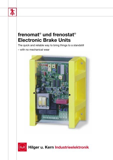
frenomat ® <strong>und</strong> frenostat ®<br />
<strong>Electronic</strong> <strong>Brake</strong> <strong>Units</strong><br />
The quick and reliable way to bring things to a standstill<br />
– with no mechanical wear<br />
Hilger u. Kern Industrieelektronik
Contents<br />
Page<br />
General information . . . . . . . . . . . . . . . . . . . . . . . . . . . . . . . . . . . . . . . . . . . . . . . . . . . 3<br />
• cUL approval . . . . . . . . . . . . . . . . . . . . . . . . . . . . . . . . . . . . . . . . . . . . . . . . . . . . 3<br />
• EU Declaration of Conformity . . . . . . . . . . . . . . . . . . . . . . . . . . . . . . . . . . . . . . . 3<br />
• Line choke . . . . . . . . . . . . . . . . . . . . . . . . . . . . . . . . . . . . . . . . . . . . . . . . . . . . . . 3<br />
• Certification of mechanical stability . . . . . . . . . . . . . . . . . . . . . . . . . . . . . . . . . . . 3<br />
Application / Operating principle . . . . . . . . . . . . . . . . . . . . . . . . . . . . . . . . . . . . . . . . . 4<br />
frenomat 2 brake unit . . . . . . . . . . . . . . . . . . . . . . . . . . . . . . . . . . . . . . . . . . . . . . . . . . 5<br />
frenostat 1000 brake unit . . . . . . . . . . . . . . . . . . . . . . . . . . . . . . . . . . . . . . . . . . . . . . . 6<br />
frenostat 2000 brake unit . . . . . . . . . . . . . . . . . . . . . . . . . . . . . . . . . . . . . . . . . . . . . . . 7<br />
Technical data: frenomat 2/frenostat 2000 brake units . . . . . . . . . . . . . . . . . . . . . . . . 9<br />
Dimensions: frenostat 2000 . . . . . . . . . . . . . . . . . . . . . . . . . . . . . . . . . . . . . . . . . . . . 10<br />
Examples of circuits: frenostat 2000 . . . . . . . . . . . . . . . . . . . . . . . . . . . . . . . . . . 11-14<br />
Accessory: line choke . . . . . . . . . . . . . . . . . . . . . . . . . . . . . . . . . . . . . . . . . . . . . . . . . 14<br />
Commissioning: frenomat 2/frenostat 2000 . . . . . . . . . . . . . . . . . . . . . . . . . . . . . . . 15<br />
International sales organization . . . . . . . . . . . . . . . . . . . . . . . . . . . . . . . . . . . . . . . . . 15<br />
2
General information<br />
cUL approval<br />
frenostat and frenomat brake units listed<br />
at Underwriters Laboratories Inc.<br />
Important for all export-oriented companies:<br />
As of immediately, all frenostat and<br />
frenomat brake units from Hilger u. Kern<br />
Industrieelektronik are cUL listed. The UL<br />
File Number is 225692 and the Control<br />
No. is 1 Y D 1.<br />
Listed units with UL makes it easier to<br />
export machinery and installations to the<br />
USA and Canada.<br />
The UL-listed Size 2 is made of sheet<br />
steel and the line choke is integrated in<br />
the unit. Size 1 (36 and 60 A) is now<br />
supplied as a new plastic version.<br />
EU Declaration of Conformity<br />
Hilger u. Kern Industrieelektronik here with<br />
declares with respect to the products it<br />
manufactures and named below<br />
frenomat electronic brake unit,<br />
frenostat electronic brake unit,<br />
that the requirements relating to electromagnetic<br />
compatibility (EMC) as laid down<br />
in EU Directive 89/336/EEC are met.<br />
Assessment of the product has been based<br />
on the following standards:<br />
• IEC 947-4-2 AC semiconductor motor<br />
controllers and starters<br />
• EN 50081-1 Generic Emission Standard<br />
03.93<br />
• EN 50082-2 Generic Immunity Standard<br />
08.94<br />
The corresponding measurements have<br />
been confirmed and documented by the<br />
German technical inspectorate TÜV-Südwest<br />
in Mannheim.<br />
The units named above are labeled with a<br />
CE mark of conformity.<br />
Line choke<br />
The emission limits laid down in the European<br />
standards do not exclude interference<br />
of receivers within a radius of 10 m.<br />
During operation, i.e. braking, frenostat<br />
and frenomat electronic brake units remain<br />
within the limits of European standard EN<br />
50081-2 (mains-borne interference) with<br />
regard to the power cables if a line choke<br />
is installed directly on the line terminal.<br />
This accessory is available from Hilger u.<br />
Kern Industrieelektronik (see page 14).<br />
The enclosures of the frenostat brake<br />
units are made of environmentally friendly,<br />
recyclable materials.<br />
Certification of<br />
mechanical stability<br />
frenostat electronic brake unit No.<br />
12524100 has been subjected to a type<br />
test in accordance with DIN 57 Part<br />
2/VDE 0160 Part 2, Section 4.2.<br />
This test is valid for all frenostat brake<br />
units that have been manufactured since<br />
January 1, 1978.<br />
The results of the measurements taken<br />
have revealed that the brake unit more<br />
than complies with the requirements laid<br />
down in VDE 0160 Part 2, Section 4.2.<br />
Operational reliability of the frenostat brake<br />
unit was unaffected.<br />
3
Application /<br />
Operating principle<br />
frenomat and frenostat electronic brake<br />
units<br />
• reliably and quickly brake asynchronous<br />
motors to a standstill without<br />
requiring any maintenance or suffering<br />
any wear.<br />
• are the perfect solution for shortening<br />
long coasting times (saving time and<br />
costs).<br />
• are components that can be retrofitted<br />
in control cabinets without any problem.<br />
• are maintenance- and wear-free.<br />
Due to systematic action taken to meet<br />
the demands of the market, frenomat and<br />
frenostat electronic brake units have a<br />
wider power spectrum than units comparable<br />
in design. In particular, the following<br />
features designed to increase service reliability<br />
must be highlighted:<br />
• visual indication of the operating state<br />
• proven snubber circuit to protect<br />
against voltage peaks<br />
• generous rating of the heat sinks<br />
• high degree of service reliability – even<br />
<strong>und</strong>er rough service and ambient<br />
conditions – thanks to protective<br />
lacquering<br />
• captive connecting screws<br />
• automatic standstill monitoring.<br />
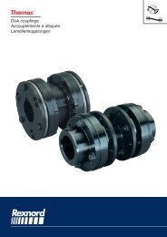
Basic circuitry<br />
of the main circuit<br />
(basic layout)<br />
▲<br />
Braking torque curve with<br />
asynchronous motors as<br />
a factor of the speed<br />
▲<br />
▲<br />
Operating principle<br />
A rugged power converter, working in<br />
conjunction with floating, digital control<br />
electronics, generates a powerful braking<br />
torque.<br />
The braking effect is initiated by an<br />
adjustable direct current that flows through<br />
the motor winding. A stationary magnetic<br />
field, which acts as a static field, retards<br />
the rotational movement of the rotor. The<br />
braking torque that results from this follows<br />
the curve depicted against the speed.<br />
Application example:<br />
vibrating screen<br />
A frenostat 2000 electronic brake unit<br />
brings the 30-kW drive to a standstill within<br />
just a few seconds. This prevents dangerous<br />
sympathetic (resonant) oscillations.<br />
Use of the frenostat 2000 made it possible<br />
to do without elaborate and costly concrete<br />
fo<strong>und</strong>ations.<br />
4
frenomat 2<br />
electronic brake unit<br />
The frenomat 2 electronic brake unit<br />
quickly and reliably brakes three-phase<br />
AC motors with a power output of up to 3<br />
kW. frenomat 2 brake units are compact<br />
and suitable for snap-fitting on DIN rails.<br />
They are only 55 mm wide!<br />
The control and power circuits are housed<br />
in a rigid and unbreakable plastic enclosure.<br />
The braking current and braking time are<br />
both infinitely variable and can be adjusted<br />
manually.<br />
frenomat 2 is also equipped with a standstill<br />
monitoring unit on terminal n1 to allow it<br />
to be used with drives whose rotating<br />
mass is frequently changed.<br />
Circuit diagram<br />
Dimensions<br />
▲ ▲<br />
5
frenostat 1000 electronic brake unit<br />
The frenostat 1000 brake unit is used to<br />
brake asynchronous motors with a power<br />
output of 4 or 7.5 kW (max. braking current<br />
25 A , 40 A or 60 A only in combination<br />
with an external braking contactor).<br />
The unit is equipped with a standstill<br />
monitoring unit on terminal T3. The braking<br />
current is infinitely variable and can be<br />
adjusted by means of a potentiometer.<br />
A braking relay is integrated into the unit,<br />
which means there is no need for additional<br />
wiring-up of a braking contactor.<br />
An internal interlocking contact (11, 12, 13)<br />
is employed to enable the motor contactor.<br />
The operating states “Power”, “Motor” and<br />
“<strong>Brake</strong>” are indicated by means of lightemitting<br />
diodes.<br />
frenostat 1000 is supplied in an unbreakable<br />
plastic enclosure. It is installed in the<br />
control cabinet by being snap-fitted onto<br />
a DIN rail.<br />
Dimensions:<br />
Width 45 x height 149 x depth 190 mm<br />
6
frenostat 2000 electronic brake unit<br />
This type of brake unit is used to quickly<br />
and reliably brake three-phase AC motors<br />
within a power output range from 3 to 100<br />
kW to a standstill.<br />
frenostat 2000 is available in 4 different<br />
sizes.<br />
Braking current control<br />
The frenostat 2000 braking units use an<br />
integral braking current measurement<br />
function to control the amperage and the<br />
braking force to the specified values set.<br />
This simplifies commissioning and dispenses<br />
with the need for time-consuming<br />
measurement procedures. An ammeter is<br />
not required to set the current.<br />
The current level is indicated by means of<br />
a bar display.<br />
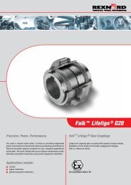
Control /<br />
Status indicators<br />
All important operating statuses are indicated<br />
by means of LEDs.<br />
➀ “P” – Fuse monitoring<br />
➁ “M” – Motor On<br />
➂ “B” – <strong>Brake</strong> active<br />
➃ “S” –<br />
➄ “O” –<br />
Standstill monitoring by<br />
sensing the motor's rotational<br />
movement<br />
Overheating indicator flashes<br />
frenostat 2000 electronic brake units can<br />
be controlled both by means of contactor<br />
equipment or a PLC.<br />
(24-V logic)<br />
➅ Potentiometer for time adjustment<br />
➆ Potentiometer for braking current<br />
adjustment<br />
➇ Braking current display<br />
➀ ➁ ➂ ➃ ➄ ➅ ➆ ➇<br />
Braking current display<br />
LED frenostat 2000 brake units are<br />
equipped with an LED bar displa<br />
This display indicates the instantaneous<br />
braking current in 10% steps.<br />
7
Overheating protection<br />
In order to increase operational reliability,<br />
frenostat 2000 brake units are equipped<br />
with an integral temperature-measuring<br />
function.<br />
In the event of the unit overheating, due<br />
to too frequent braking for example, braking<br />
is executed until the motor comes to a<br />
standstill, but the motor is prevented from<br />
restarting. A floating relay contact (n3, n4)<br />
remains closed. In addition, LED “O”<br />
flashes to indicate overheating.<br />
Once the brake unit has cooled down to<br />
its normal operating temperature, the<br />
relay contact (n3, n4) is opened again.<br />
LED “O” stops flashing.<br />
Standstill monitoring<br />
An integrated standstill monitoring unit<br />
alters the operating time of the brake<br />
depending on the variable rotating mass<br />
of the overall drive. A manual time setting<br />
is not needed.<br />
Activation of this monitoring unit is indicated<br />
by LED “S”.<br />
The control unit is connected to terminal<br />
n1 by means of an instrument lead (0.75<br />
mm 2 ). Measurement is triggered by the<br />
braking contactor by means of an auxiliary<br />
contact. If motor leads with a cross-section<br />
>1.5 mm 2 are used, a 2-A fuse must be<br />
fitted to protect the instrument lead.<br />
Interlocking contact<br />
frenostat brake units are equipped with a<br />
floating changeover contact. NC contact<br />
n4 – n2 opens after the motor has started<br />
and in this way allows the motor to be<br />
started again only after braking has been<br />
completed.<br />
The interlocking contact can perform the<br />
following functions:<br />
• protect against overheating<br />
• interlock immediate reclosure following<br />
the OFF command without braking (see<br />
examples of circuits)<br />
• indicate readiness: the motor is only<br />
released by a PLC for reclosure once<br />
the contact is in its normal position<br />
• interlock a hood or cover: a protective<br />
hood or cover can only be opened<br />
when the drive is at rest<br />
• report standstill<br />
• open a mechanical holding brake.<br />
Choice of brake unit fuses<br />
The 2 brake unit fuses serve among other<br />
things to protect the motor against overloading.<br />
These fuses must be adapted to<br />
match the rated current of the motor.<br />
Rated fuse current = approx. 150% of rated<br />
motor current. See basic circuit on page<br />
13 for circuitry of fuse F4.<br />
Choice of braking contactor<br />
Size of braking contactor = size of motor<br />
contactor. The contactor is energized and<br />
de-energized without current being applied<br />
to the main contacts.<br />
Size of connection cables<br />
The cross-section of the cables connected<br />
to terminals 8, a and b is identical to that<br />
of the motor connection cables.<br />
The cable connected to terminal n1 is an<br />
instrument lead (
frenomat 2/frenostat 1000/frenostat 2000 electronic brake units<br />
Technical data<br />
Maximum braking current:<br />
frenomat 2<br />
frenostat 1000<br />
frenostat 2000 Size 1<br />
frenostat 2000 Size 2<br />
frenostat 2000 Size 3<br />
frenostat 2000 Size 4<br />
30 A<br />
25, 40, 60 A<br />
36, 60 A<br />
100, 150, 200 A<br />
300, 400, 500 A<br />
750, 1000, 1500 A<br />
Input braking voltage:<br />
+ 10%/ - 15% at 50 to 60 Hz<br />
230 V to 500 V<br />
higher than 500 V on request<br />
Max. output braking voltage:<br />
(V) DC<br />
Line voltage<br />
AC<br />
Braking current<br />
DC<br />
230 V 80 V<br />
400 V 160 V<br />
500 V 190 V<br />
660 V 270 V<br />
Ambient temperature:<br />
- 25°C to + 45°C at nominal output;<br />
and + 60°C, reduction in at temperatures<br />
between + 45°C braking current of 1.5%<br />
necessary per °C<br />
Contact load:<br />
250 V / 5 A (at terminals 3 and 4)<br />
Braking time:<br />
0 to 12 seconds;<br />
when a standstill monitoring the braking<br />
time is set automatically unit is connected<br />
to terminal n1/T3<br />
ON time:<br />
20% in relation to 1 min. (12 s/min.)<br />
Please inquire about longer ON times<br />
External fuses:<br />
frenomat – max. 16 A<br />
frenostat – approx. 150%<br />
of rated motor current<br />
9
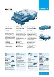
▲ ▲<br />
Dimensions<br />
frenostat 2000 Size 1<br />
36 A and 60 A<br />
Height x width x depth<br />
185 x 158 x 110 mm<br />
Drilling dimensions in mm<br />
145 x 137 ø 5.5 mm<br />
Weight: 1.1 kg<br />
Line choke for assembly outside<br />
the unit (optional)<br />
frenostat 2000 Size 2<br />
100 A, 150 A and 200 A<br />
Height x width x depth<br />
270 x 145 x 180 mm<br />
Drilling dimensions in mm<br />
130 x 215 ø 6.5 mm<br />
Weight: 7.5 kg<br />
Line choke installed in unit<br />
frenostat 2000 Size 3<br />
300 A, 400 A and 500 A<br />
Height x width x depth<br />
270 x 145 x 180 mm<br />
Drilling dimensions in mm<br />
130 x 215 ø 6.5 mm<br />
Weight: 6.5 kg<br />
Line choke separate outside the unit<br />
▲<br />
10
Examples of circuits: frenostat 2000 electronic brake unit<br />
▲<br />
Circuit diagram 1<br />
Basic circuit<br />
▲<br />
Circuit diagram 2<br />
Motor control for reversing operation<br />
11
▲<br />
Circuit diagram 3<br />
Motor control for star-delta starting; braking with star connection (2 motor windings connected in series)<br />
▲<br />
Circuit diagram 4<br />
Motor control for problem circuitry (Dahlander); braking acting on the motor winding at high speed<br />
12
▲<br />
Circuit diagram 5<br />
Motor control for pole changing; braking acting on the motor winding at high speed<br />
▲<br />
Circuit diagram 6<br />
2-motor control; braking with series connection for motors >2 kW<br />
13
▲<br />
Circuit diagram 7<br />
2-motor control; braking with parallel connection for motors
Commissioning<br />
frenomat 2/frenostat 2000 electronic brake units<br />
N.B.<br />
• <strong>Electronic</strong> printed-circuit boards are live.<br />
• Connect heat sinks to gro<strong>und</strong>.<br />
• Avoid using a long supply lead.<br />
• Use an ohmmeter or multimeter.<br />
Do not use a continuity tester or test lamp.<br />
Activating without<br />
braking current<br />
Test interlocking<br />
Remove the fuse from the motor. Set potentiometer<br />
“T” (time) to max. (turn clockwise<br />
as far as it will go) and potentiometer “I”<br />
(current) to min. (turn counterclockwise as<br />
far as it will go).<br />
Motor contactor<br />
K 1<br />
On<br />
on<br />
Off<br />
Braking contactor<br />
K 2<br />
Off<br />
K 1 cannot be energized,<br />
off - K On 1 interlocked<br />
Test interlock: Energize K 2 by hand Energize K 1 by hand<br />
K 1 de-energizes<br />
K 2 de-energizes<br />
▲<br />
Operating principle<br />
Setting the braking current<br />
Note<br />
Throw the motor fuse and turn potentiometer<br />
“T” (time) through a 1/4 turn. When<br />
the motor has reached its normal operating<br />
temperature, slowly turn potentiometer “I”<br />
(current) clockwise during braking and<br />
observe the current value on the LED bar<br />
display while doing so. 10 bars = 100%<br />
indication = rated current of the unit.<br />
During braking, LEDs “B” (braking) and “S”<br />
(standstill) light up. “B” indicates energizing<br />
of the output relays on terminals 3 and 4<br />
and “S” monitors the rotation of the motor<br />
(On) until the standstill (Off).<br />
With frenostat 1000 : connect a DC -<br />
ammeter to terminal T2.<br />
With frenomat – 2 : connect a DC ammeter<br />
tpo terminal b.<br />
LED “S” is off when braking is completed.<br />
The braking time set at potentiometer “T”<br />
(time) accumulates automatically. This can<br />
be set manually for post-braking that can<br />
last up to 20 seconds.<br />
LED “O” (overheating) flashes if the heat<br />
sinks of the brake unit have become too<br />
hot due to too frequent braking. The motor<br />
cannot start again as long as this LED<br />
flashes.<br />
frenostat 1000 and frenomat are not<br />
equipped with overheating protection.<br />
International sales organization<br />
Australia<br />
Fraser, Hrones & Co.PTY.ltd.<br />
NSW 2103 Mona Vale<br />
Unit 36, 12-14 Waratah Street<br />
Phone: 00612 / 99796333<br />
Italy<br />
Transtecno S.R.L.<br />
Via Caduti di Sabbiuno, 11D/E<br />
40011 Anzolo Emilia (Bo)<br />
Phone: 00390 / 51731487<br />
Finland<br />
OY HedTec AB<br />
Postfach 110<br />
201 Helsinki<br />
Phone: 00358 / 968281<br />
Netherlands<br />
Bakker & Co.B.V.<br />
Postbus 1235<br />
3330 CE Zwijndrecht<br />
Phone: 0031 / 786101666<br />
France<br />
DOPAG S.a.r.L.<br />
B.P. 64<br />
26903 Valence<br />
Phone: 0033 / 475419060<br />
Spain<br />
Hermann-Otto Suderow S.L.<br />
Apartado 135<br />
48930 Las Arenas (Vizcaya)<br />
Phone: 00349 / 44800018<br />
Great Britain<br />
Stromag Ltd.<br />
29 Wellingborough Road<br />
Rushden, Northants<br />
NN10 9YE<br />
Phone: 0044 / 193350407<br />
Czech Republic<br />
ELGO Electric s.r.o<br />
Kourimska 103<br />
28000 Kolin 1<br />
Phone: 00420 / 32124489<br />
15
The Hilger u. Kern / Dopag Group, which employs a workforce of more than 320 and has 6 international<br />
subsidiaries, is one of the world's largest manufacturers of metering and mixing systems, systems that<br />
deploy all processing concepts commonly in use for polymers and single-component media such as<br />
greases, oils and adhesives.<br />
The Group has been developing and building machines, installations and one-off units tailored specifically<br />
to your requirements for more than 25 years.<br />
Comprising 4 separate divisions specializing in Drive Technology, Metering Technology, Industrial<br />
<strong>Electronic</strong>s and Spray Technology, Hilger u. Kern Industrietechnik, located in Mannheim, is one Germany's<br />
leading manufacturers of technically sophisticated, innovative and high-quality capital goods.<br />
Hilger u. Kern GmbH<br />
Germany<br />
Dopag Headquarters<br />
Switzerland<br />
Drive Technology<br />
Friction-locking and<br />
positive drive systems<br />
Planetary gearing<br />
Metering<br />
Technology<br />
Mixing and metering systems for<br />
polymers and 1-component media<br />
Industrial <strong>Electronic</strong>s<br />
<strong>Electronic</strong> softstarters and<br />
brake units, microcomputers,<br />
machine monitoring systems<br />
Spray Technology<br />
Spray system, material supply,<br />
customized systems<br />
Dopag SCAN Aps<br />
Denmark<br />
Dopag UK Ltd.<br />
England<br />
Dopag S.A.R.L.<br />
France<br />
Dopag SDN. BHD<br />
Malaysia<br />
Dopag Sverige AB<br />
Sweden<br />
Hilger u. Kern Industrieelektronik<br />
Hilger u. Kern GmbH · Käfertaler Straße 253 · 68167 Mannheim · DEUTSCHLAND<br />
Phone: +49 (0)621 / 37 05 - 0 · Fax: +49 (0)621 / 37 05 - 2 00 · E-mail: industrieelektronik@hilger-kern.de · Home: www.hilger-kern.com<br />
VDE 203-2/03.2-Stork © by Hilger u. Kern Industrieelektronik Subject to change without prior notice.