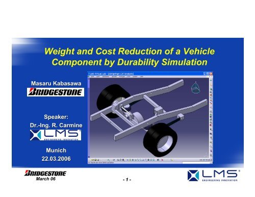
Weight and Cost Reduction of a Vehicle Component by Durability ...
Weight and Cost Reduction of a Vehicle Component by Durability ...
Weight and Cost Reduction of a Vehicle Component by Durability ...

Create successful ePaper yourself
Turn your PDF publications into a flip-book with our unique Google optimized e-Paper software.
<strong>Weight</strong> <strong>and</strong> <strong>Cost</strong> <strong>Reduction</strong> <strong>of</strong> a <strong>Vehicle</strong><br />
<strong>Component</strong> <strong>by</strong> <strong>Durability</strong> Simulation<br />
Masaru Kabasawa<br />
Speaker:<br />
Dr.-Ing. R. Carmine<br />
Munich<br />
22.03.2006<br />
March 06<br />
- 1 -
Contents:<br />
• Objectives<br />
• CAE Approach for Fatigue Life Analysis<br />
• Modeling Procedure<br />
• Multi Body Simulation<br />
• Methodology <strong>of</strong> <strong>Durability</strong> Analysis<br />
• Fatigue Analysis for Road Load Data<br />
• Conclusion<br />
March 06<br />
- 2 -
Objectives:<br />
CAE based Assessment <strong>of</strong> the Structural Integrity <strong>of</strong><br />
an Air Suspension System<br />
<strong>Component</strong>s:<br />
• Frame<br />
• CLink<br />
(Trailing Arm)<br />
Tasks:<br />
• <strong>Cost</strong> <strong>and</strong> <strong>Weight</strong> <strong>Reduction</strong><br />
• Stress Recovery <strong>and</strong> Fatigue Life Analysis for Road Load Data<br />
March 06<br />
- 3 -
CAE Approach for Fatigue Life Analysis:<br />
Virtual Testing<br />
• CAE Process:<br />
• What<br />
Finite Element based Fatigue Simulation<br />
+ +<br />
From LMS NEWS (IGEL Test Rig)<br />
from LMS NEWS (BMW Model)<br />
March 06<br />
- 4 -
CAE Approach for Fatigue Life Analysis:<br />
Work Flow<br />
• CAE Process: Fatigue Life Analysis<br />
„Load Model“: Multibody Model <strong>of</strong> <strong>Vehicle</strong><br />
Input Data: Measured Wheel Loads (Forces + Moments)<br />
Output Data<br />
<strong>Component</strong> Loads<br />
F<br />
( t) M ( t)<br />
i<br />
,<br />
i<br />
„Stress Model“: FE Model <strong>Component</strong><br />
From LMS NEWS (BMW)<br />
r<br />
σ ( x,<br />
t)<br />
i<br />
Input Data: <strong>Component</strong> loads<br />
Output Data:<br />
Stress-Time Series<br />
on <strong>Component</strong><br />
Fatigue Life Prediction (FLP)<br />
Input Data: Stress-time Series on <strong>Component</strong><br />
With Courtesy <strong>of</strong> AUDI<br />
r<br />
d( x)<br />
N( r<br />
x)<br />
Output Data:<br />
Life to Crack Initiation<br />
(Base Material, Welded Joints)<br />
March 06<br />
- 5 -
Modeling Procedure:<br />
Multi Body System <strong>of</strong> Rear Suspension<br />
Damper<br />
Left<br />
Lateral<br />
Arms<br />
Air<br />
Spring<br />
Flexible<br />
Frame<br />
Rigid<br />
Axle<br />
Damper<br />
Right<br />
Flexible<br />
CLink<br />
Right<br />
March 06<br />
- 6 -
Modeling Procedure: Multi Body Modeling:<br />
Air Spring Characteristics<br />
Nonlinear Dynamic Spring Rate<br />
Dependent <strong>of</strong> Total <strong>Weight</strong>:<br />
Laden: 2800 lbf 85 psi<br />
Unladen: 1000 lbf 32 psi<br />
Measured Dynamic Spring Rate<br />
Laden<br />
Unladen<br />
Resulting Air Spring Curves<br />
xxx<br />
xxx<br />
xxx<br />
xxx<br />
xxx<br />
xxx<br />
March 06<br />
- 7 -
Modeling Procedure: Multi Body Modeling:<br />
Dampers Characteristic<br />
Nonsymmetric<br />
Configuration<br />
Two Damper Curves:<br />
S<strong>of</strong>t: 0-400<br />
psi<br />
Firm: 65 psi-up<br />
March 06<br />
- 8 -
Modeling Procedure: Multi Body Modeling:<br />
Bushing Characteristics<br />
• Bushing<br />
Locations<br />
• Axial<br />
• Radial<br />
• Conical<br />
• Torsional<br />
• Stiffness<br />
• Damping<br />
March 06<br />
- 9 -
Modeling Procedure: Multi Body Modeling:<br />
Axle as rigid body in Multi Body System<br />
• Mass Axle = 330 kg<br />
• Mass one Wheel = 38 kg<br />
• Total Mass = 406 kg<br />
4 connection points to Trailing Arm<br />
1 connection point to Connector Lateral Control Arms<br />
2 connection points to Air Springs<br />
2 connection points to Dampers<br />
2 connection points to the wheels<br />
March 06<br />
- 10 -
Modeling Procedure: Finite Element Modeling:<br />
Frame as flexible body<br />
• 53000 linear Shell Elements in NASTRAN, 1200 Seamweld Elements<br />
11 Connection Points<br />
to suspension components<br />
<strong>and</strong> ground:<br />
10*6 +1*3 = 63 Static modes<br />
10 normal modes<br />
67 Craig Bampton modes<br />
Structural Viscous Damping = 5%<br />
Mass = xxx<br />
March 06<br />
- 11 -
Modeling Procedure: Finite Element Modeling:<br />
CLink as flexible body (Variant 1)<br />
• 67000 Tet10 Elements<br />
• 29000 Tria6 Skinning Elements<br />
2 Connection Points to axle<br />
1 connection point to frame<br />
3*6 = 18 Static modes<br />
+<br />
10 normal modes<br />
-<br />
6 rigid body modes<br />
=<br />
22 Craig Bampton modes<br />
Casted Steel<br />
Mass : 100%<br />
<strong>Cost</strong> : 100%<br />
March 06<br />
- 12 -
Modeling Procedure: Finite Element Modeling:<br />
CLink as flexible body (Variant 2)<br />
• 10000 linear Quad4 Elements<br />
• 300 linear Seam Weld Elements<br />
22 Craig Bampton Modes<br />
Welded Sheet<br />
Mass : 50%<br />
<strong>Cost</strong> : 75%<br />
March 06<br />
- 13 -
Methodology <strong>of</strong> <strong>Durability</strong> Analysis:<br />
General Work Flow<br />
Wheel Forces<br />
Multi Body Simulation<br />
Craig Bampton<br />
Displacement<br />
Modes<br />
Craig Bampton<br />
Load Cases<br />
Finite Element<br />
Modal Analysis<br />
Modal Participation<br />
Factor Histories<br />
Craig Bampton<br />
Stress Modes<br />
Generation <strong>of</strong> Local<br />
Stress Tensor History<br />
And Damage Evaluation<br />
Stress Amplitude<br />
Distribution<br />
Damage Distribution<br />
March 06<br />
- 14 -
Multibody Simulation:<br />
Input Static Loads: Three Load Cases<br />
Each Load Case consists <strong>of</strong> two forces<br />
at tire contact patch point<br />
Results: : Hot Spots at Brackets<br />
Lateral Wheel Forces:xxx N<br />
Vertical Wheel Forces:<br />
xxx N<br />
Longitudinal Wheel Forces: xxx N<br />
March 06<br />
- 15 -
Multibody Simulation :<br />
Input Data: Load Histories Road Load Data<br />
Drive Fully Laden: Load Histories at Wheel Contact Patch<br />
Load <strong>Weight</strong>: xxx lbf xxx N / Wheel<br />
• Fz left side<br />
• Fz right side<br />
March 06<br />
- 16 -
Fatigue Analysis for Road Load Data:<br />
Result: Multi Body Simulation<br />
March 06<br />
- 17 -
Methodology <strong>of</strong> <strong>Durability</strong> Analysis:<br />
General Work Flow<br />
Wheel Forces<br />
Multi Body Simulation<br />
Craig Bampton<br />
Displacement<br />
Modes<br />
Craig Bampton<br />
Load Cases<br />
Finite Element<br />
Modal Analysis<br />
Modal Contribution<br />
Factor Histories<br />
Craig Bampton<br />
Stress Modes<br />
Generation <strong>of</strong> Local<br />
Stress Tensor History<br />
And Damage Evaluation<br />
Stress Amplitude<br />
Distribution<br />
Damage Distribution<br />
March 06<br />
- 18 -
Methodology <strong>of</strong> <strong>Durability</strong> Analysis:<br />
Step 1: Stress Recovery for Transient Loads<br />
(stress) mode shapes<br />
…<br />
β 1 (t)<br />
modal contribution<br />
factor histories<br />
[ c ij ] 1<br />
[ c ij ] m<br />
modal influence<br />
coefficients:<br />
β m (t)<br />
time, t<br />
e σ ij (t) = ∑ m [ c ij • β(t)<br />
] m<br />
March 06<br />
- 19 -
Methodology <strong>of</strong> <strong>Durability</strong> Analysis:<br />
Fatigue Life Prediction for Sheet Material<br />
Stress-Life Approach:<br />
e σ x<br />
e τ xy<br />
e σ ξ<br />
e τ ξη<br />
e σ y<br />
α<br />
FE-result<br />
result: Elastic Stresses<br />
• initiation <strong>and</strong> growth <strong>of</strong><br />
small cracks<br />
analyze potentially critical<br />
(crack) planes<br />
evaluate uni-axial pseudo-<br />
stress history in each plane<br />
simultaneous treatment <strong>of</strong><br />
all planes to find most<br />
severe damage<br />
maximum damage defines<br />
critical plane<br />
March 06<br />
- 20 -
Methodology <strong>of</strong> <strong>Durability</strong> Analysis:<br />
Fatigue Life Prediction for Sheet Material<br />
Critical Plane Approach:<br />
e<br />
σ x<br />
S<br />
e<br />
τ xy<br />
e<br />
σ ξ<br />
e<br />
τ ξη<br />
March 06<br />
e<br />
σ y<br />
N<br />
α<br />
e<br />
σ ξ<br />
e<br />
τ ξη<br />
e<br />
σ x<br />
e<br />
σ y<br />
e<br />
τ xy<br />
ξη<br />
α = 0 o<br />
- 21 -<br />
time<br />
damage accumulation<br />
10 o ... 160 o<br />
...<br />
...<br />
...<br />
time<br />
e<br />
σ ξ<br />
e<br />
τ ξη<br />
170 o<br />
time<br />
damage accumulation<br />
D(α=0 o ) D(α=170 o )<br />
D = max[ D(α) ]
Methodology <strong>of</strong> <strong>Durability</strong> Analysis:<br />
Fatigue Life Prediction for Seam Welds:<br />
RxMS Approach:<br />
• LMS Virtual.Lab combines a<br />
shell based FE model <strong>and</strong> a 3D<br />
fine model to simulate the<br />
stress tensor histories in the<br />
weld toe <strong>and</strong> root.<br />
• RxMS SN-curve<br />
log(S)<br />
Seam Weld SN curve<br />
log(N)<br />
F<br />
M<br />
Coarse<br />
Model<br />
Transition<br />
Matrix<br />
Fine<br />
Model<br />
σ<br />
s<br />
s<br />
F M<br />
All stress<br />
concentration<br />
factors<br />
K t<br />
R03MS<br />
R = 0.3 mm for weld toes <strong>and</strong> root<br />
March 06<br />
- 22 -
Methodology <strong>of</strong> <strong>Durability</strong> Analysis:<br />
Fatigue Life Prediction for Seam Weld:<br />
LMS Virtual.Lab Seam Weld Analysis:<br />
• Automates the well accepted<br />
RxMS approach.<br />
• No FE mesh adaptations<br />
required<br />
• Automatic detecting <strong>of</strong> seam<br />
welds – location <strong>and</strong> type<br />
• High Amount <strong>of</strong> accurate<br />
solid models for seam welds<br />
in open database<br />
Subframe Mercedes Benz<br />
March 06<br />
- 23 -
Methodology <strong>of</strong> <strong>Durability</strong> Analysis:<br />
Fatigue Life Prediction for Seam Weld:<br />
Seam Weld Modelling:<br />
Congruent mesh for two welded sheets<br />
shell elements<br />
March 06<br />
- 24 -
Methodology <strong>of</strong> <strong>Durability</strong> Analysis:<br />
Fatigue Life Prediction for Seam Weld<br />
Automated Seam Welds Recognition<br />
March 06<br />
- 25 -
Methodology <strong>of</strong> <strong>Durability</strong> Analysis:<br />
General Work Flow<br />
Wheel Forces<br />
Multi Body Simulation<br />
Craig Bampton<br />
Displacement<br />
Modes<br />
Craig Bampton<br />
Load Cases<br />
Finite Element<br />
Modal Analysis<br />
Modal Participation<br />
Factor Histories<br />
Craig Bampton<br />
Stress Modes<br />
Generation <strong>of</strong> Local<br />
Stress Tensor History<br />
And Damage Evaluation<br />
Stress Amplitude<br />
Distribution<br />
Damage Distribution<br />
March 06<br />
- 26 -
Fatigue Analysis for Road Load Data:<br />
Input Data: Stress Tensor Histories<br />
• Multi Body Simulation creates 22 Modal Contribution Factor<br />
Histories assigned to the 22 Craig Bampton Modes<br />
MPFH<br />
CB Modes<br />
e σ ij (t) = ∑ m [ c ij • β(t)<br />
] m<br />
March 06<br />
- 27 -
Fatigue Analysis for Road Load Data:<br />
Input Parameters: Seam Welds<br />
• The seam weld type is recognized automatically<br />
• For the seam weld type there is assigned the right micro<br />
model <strong>of</strong> the seam weld shape automatically<br />
SN-curve<br />
selected:<br />
R03MS Steel (R=-1)<br />
Slope: : 3.75<br />
Endurance Limit:<br />
• 331 MPa<br />
• 5*10 6 cycles<br />
March 06<br />
- 28 -
Fatigue Analysis for Road Load Data:<br />
Input Data: Casted Steel & Sheet Material<br />
• Materials Data<br />
Stress – Cycles to crack initiation curve<br />
• Critical Plane Approach (Mode 1)<br />
March 06<br />
- 29 -
Fatigue Analysis for Road Load Data:<br />
Stress Analysis for C-Links (Variant 1)<br />
• Max. Stress Amplitude far below endurance limit<br />
• Safety Factor to Endurance Limit is 4.6<br />
• Damage Value is zero all over the structure<br />
Casted Steel<br />
Mass : 100%<br />
<strong>Cost</strong> : 100%<br />
March 06<br />
- 30 -
Fatigue Analysis for Road Load Data:<br />
Stress Analysis for C-Links (Variant 2)<br />
• Max. Stress Amplitude far below endurance limit<br />
• Safety Factor to Endurance Limit is 4.3<br />
• Damage Value is zero all over the structure<br />
Welded Sheets<br />
Mass : 50%<br />
<strong>Cost</strong> : 75%<br />
March 06<br />
- 31 -
Fatigue Analysis for Road Load Data:<br />
Seam Weld Analysis for C-Links (Variant 2)<br />
• Hot Spot 1 is at overlap joint <strong>of</strong> additional sheet<br />
• Hot Spot 2 is at seam weld end <strong>of</strong> overlap joint<br />
• 2.000.000 repeats <strong>of</strong> the simulated block until crack initiation<br />
HS2:<br />
HS1:<br />
March 06<br />
- 32 -
Conclusion <strong>of</strong> Fatigue Life Analysis :<br />
• Results <strong>of</strong> Fatigue Life Analysis for C-Links<br />
(Trailing<br />
Arms):<br />
• Stress Amplitudes for both Variants are far below Endurance<br />
Limit, Safety Factors are near to each other<br />
• There were identified two Hotspots for the Seamwelds<br />
• The casted steel CLink can be substituted <strong>by</strong> the welded sheet<br />
construction<br />
• Further Tasks:<br />
• Compare Strain Gage Measurement results at Test Rig with<br />
Simulation Results<br />
• Compare Crack Initiation Locations (Hot Spots)<br />
Test Rig - Simulation : Location + Life Time<br />
March 06<br />
- 33 -