

Catalog
Catalog
Catalog

Create successful ePaper yourself
Turn your PDF publications into a flip-book with our unique Google optimized e-Paper software.
Conductive Elastomer Gasket Design continued<br />
Fastener Requirements<br />
1. Applied Force<br />
Most applications do not require<br />
more than 100 psi (0.69 MPa) to<br />
achieve an effective EMI seal.<br />
Waveguide flanges often provide<br />
ten times this amount. Hollow strips<br />
require less than 10 pounds per in.<br />
Compression deflection data for<br />
many shapes, sizes and materials is<br />
included in the Performance Data<br />
section of this handbook.<br />
The force required at the point of<br />
least pressure, generally midway<br />
between fasteners, can be obtained<br />
by using a large number of small<br />
fasteners spaced closely together.<br />
Alternatively, fasteners can be<br />
spaced further apart by using stiffer<br />
flanges and larger diameter bolts.<br />
Sheet metal parts require more<br />
fasteners per unit length than<br />
castings because they lack stiffness.<br />
To calculate average applied<br />
force required, refer to load-deflection<br />
curves for specific gasket materials<br />
and cross sections (see Performance<br />
Data, page 80).<br />
2. Fastener Sizes and Spacing<br />
Fastener spacing should be<br />
determined first. As a general rule,<br />
fasteners should not be spaced<br />
more than 2.0 inches (50 mm) apart<br />
for stiff flanges, and 0.75 inch (19 mm)<br />
apart for sheet metal if high levels of<br />
shielding are required. An exception<br />
to the rule is the spacing between<br />
fasteners found in large cabinet<br />
doors, which may vary from 3 inches<br />
(76.02 mm) between centers to<br />
single fasteners (i.e., door latches).<br />
The larger spacings are compensated<br />
for by stiffer flange sections,<br />
very large gaskets, and/or some<br />
reduction in electrical performance<br />
requirements.<br />
The force per bolt is determined<br />
by dividing the total closure force by<br />
the number of bolts. Select a fastener<br />
with a stress value safely below the<br />
allowable stress of the fastener.<br />
3. Flange Deflection<br />
The flange deflection between<br />
fasteners is a complex problem<br />
involving the geometry of the flange<br />
and the asymmetrical application of<br />
forces in two directions. The onedimensional<br />
solution, which treats<br />
the flange as a simple beam on an<br />
elastic foundation, is much easier to<br />
analyze 1 and gives a good first<br />
order approximation of the spacings<br />
required between fasteners, because<br />
most EMI gaskets are sandwiched<br />
between compliant flanges.<br />
Variation in applied forces<br />
between fasteners can be limited<br />
to ±10 percent by adjusting the<br />
constants of the flange such that<br />
βd = 2,<br />
where<br />
β =<br />
where<br />
k = foundation modulus of the seal<br />
E f<br />
= the modulus of elasticity of the flange<br />
l f<br />
= the moment of inertia of the flange and seal<br />
d = spacing between fasteners<br />
The modulus of elasticity (E f ) for<br />
steel is typically 3 x 10 7 . The modulus<br />
for aluminum is typically 1 x 10 7 , and<br />
for brass it is about 1.4 x 10 7 .<br />
The foundation modulus (k) of<br />
seals is typically 10,000 to 15,000 psi.<br />
The moment of inertia (l f ) of<br />
rectangular sections, for example,<br />
may be obtained from the following<br />
expression 2 :<br />
where<br />
l f = bh 3<br />
12<br />
b is the width of the flange in contact<br />
with the gasket (inches) and<br />
h is the thickness of the flange (inches).<br />
Example<br />
Calculate the bolt spacings for<br />
flanges with a rectangular crosssection,<br />
such as shown in Figure 22,<br />
where<br />
h<br />
√ 4 k<br />
4 E f I f<br />
h is the thickness of the flange.<br />
b is the width of the flange.<br />
d is the spacing between fasteners.<br />
b<br />
d<br />
Figure 22 Bolt Spacings for Flanges<br />
N – 1<br />
Assume the flange is to be made<br />
of aluminum.<br />
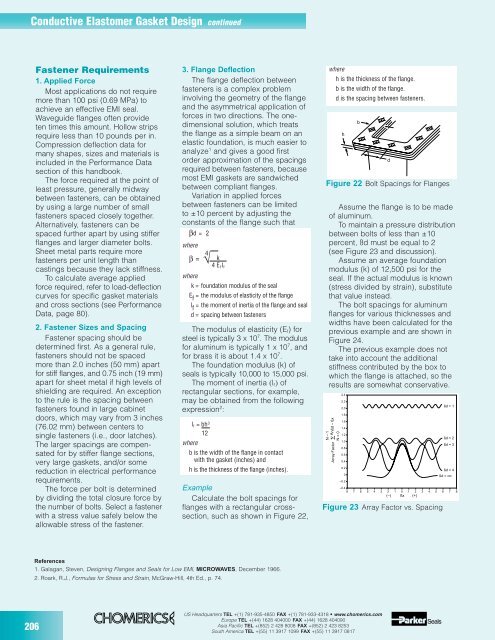
To maintain a pressure distribution<br />
between bolts of less than ±10<br />
percent, ßd must be equal to 2<br />
(see Figure 23 and discussion).<br />
Assume an average foundation<br />
modulus (k) of 12,500 psi for the<br />
seal. If the actual modulus is known<br />
(stress divided by strain), substitute<br />
that value instead.<br />
The bolt spacings for aluminum<br />
flanges for various thicknesses and<br />
widths have been calculated for the<br />
previous example and are shown in<br />
Figure 24.<br />
The previous example does not<br />
take into account the additional<br />
stiffness contributed by the box to<br />
which the flange is attached, so the<br />
results are somewhat conservative.<br />
∑ Anßd – ßx<br />
N = 0<br />
Array Factor<br />
2.4<br />
2.2<br />
2.0<br />
1.8<br />
1.6<br />
1.4<br />
1.2<br />
1.0<br />
0.8<br />
0.6<br />
0.4<br />
0.2<br />
0<br />
–0.2<br />
–0.4<br />
ßd = 1<br />
ßd = 2<br />
ßd = 3<br />
ßd = 4<br />
ßd = ∞<br />
8 7 6 5 4 3 2 1 0 1 2 3 4 5 6 7 8<br />
(–) ßx (+)<br />
Figure 23 Array Factor vs. Spacing<br />
References<br />
1. Galagan, Steven, Designing Flanges and Seals for Low EMI, MICROWAVES, December 1966.<br />
2. Roark, R.J., Formulas for Stress and Strain, McGraw-Hill, 4th Ed., p. 74.<br />
206<br />
US Headquarters TEL +(1) 781-935-4850 FAX +(1) 781-933-4318 • www.chomerics.com<br />
Europe TEL +(44) 1628 404000 FAX +(44) 1628 404090<br />
Asia Pacific TEL +(852) 2 428 8008 FAX +(852) 2 423 8253<br />
South America TEL +(55) 11 3917 1099 FAX +(55) 11 3917 0817