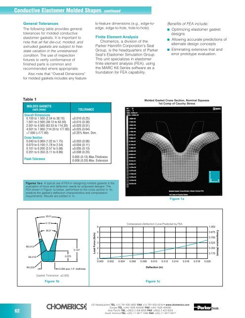
Conductive Elastomer Molded Shapes continued General Tolerances The following table provides general tolerances for molded conductive elastomer gaskets. It is important to note that all flat die-cut, molded, and extruded gaskets are subject to freestate variation in the unrestrained condition. The use of inspection fixtures to verify conformance of finished parts is common and recommended where appropriate. Also note that “Overall Dimensions” for molded gaskets includes any feature- to-feature dimensions (e.g., edge-toedge, edge-to-hole, hole-to-hole). Finite Element Analysis Chomerics, a division of the Parker Hannifin Corporation’s Seal Group, is the headquarters of Parker Seal’s Elastomer Simulation Group. This unit specializes in elastomer finite element analysis (FEA), using the MARC K6 Series software as a foundation for FEA capability. Benefits of FEA include: ■ Optimizing elastomer gasket designs ■ Allowing accurate predictions of alternate design concepts ■ Eliminating extensive trial and error prototype evaluation. Table 1 MOLDED GASKETS inch (mm) TOLERANCE Overall Dimensions 0.100 to 1.500 (2.54 to 38.10) ±0.010 (0.25) 1.501 to 2.500 (38.13 to 63.50) ±0.015 (0.38) 2.501 to 4.500 (63.53 to 114.30) ±0.020 (0.51) 4.501 to 7.000 (114.33 to 177.80) ±0.025 (0.64) >7.000 (>177.80) ±0.35% Nom. Dim. Cross Section 0.040 to 0.069 (1.02 to 1.75) ±0.003 (0.08) 0.070 to 0.100 (1.78 to 2.54) ±0.004 (0.11) 0.101 to 0.200 (2.57 to 5.08) ±0.005 (0.13) 0.201 to 0.350 (5.11 to 8.89) ±0.008 (0.20) Flash Tolerance 0.005 (0.13) Max.Thickness 0.008 (0.20) Max. Extension Molded Gasket Cross Section, Nominal Squeeze 1st Comp of Cauchy Stress Y Figures 1a-c A typical use of FEA in designing molded gaskets is the evaluation of force and deflection needs for proposed designs. The FEA shown in Figure 1a below, performed on the cross section in 1b, predicts the gasket’s deflection characteristics and compression requirements. Results are plotted in 1c. Figure 1a Z X 20.0° R0.013 R0.015 0.121 36.9° ,,,,,,,,,,,,,, ,,,,,,,,,,,,,, ,,,,,,,,,,,,,, ,,,,,,,,,,,,,, ,,,,,,,,,,,,,, ,,,,,,,,,,,,,, ,,,,,,,,,,,,,, ,,,,,,,,,,,,,, ,,,,,,,,,,,,,, ,,,,,,,,,,,,,, ,,,,,,,,,,,,,, ,,,,,,,,,,,,,, ,,,,,,,,,,,,,, ,,,,,,,,,,,,,, ,,,,,,,,,,,,,, ,,,,,,,,,,,,,, ,,,,,,,,,,,,,, 0.070 0.147 Load Force (lb/in) Compression-Deflection Curve Predicted by FEA 6 5 4 3 2 1 0 0.000 0.002 0.004 0.006 0.008 0.010 0.012 0.014 0.016 0.018 0.020 1.050 0.875 0.700 0.525 0.350 0.175 Compression (N/mm) R0.023 Gasket Tolerance: ±0.005 Figure 1b 0.090 plus 1.5° draft/side Deflection (in) Figure 1c 62 US Headquarters TEL +(1) 781-935-4850 FAX +(1) 781-933-4318 • www.chomerics.com Europe TEL +(44) 1628 404000 FAX +(44) 1628 404090 Asia Pacific TEL +(852) 2 428 8008 FAX +(852) 2 423 8253 South America TEL +(55) 11 3917 1099 FAX +(55) 11 3917 0817
,, ,,,,, ,,,,, ,,,, CONDUCTIVE ELASTOMERS Molded D- and O-Rings H ,,,, ,,,,, ,,,,, ,, W Table 2 D-RINGS Chomerics P/N* Nominal Dimensions H W I.D. 10-01-6515-XXXX 0.048 (1.22) 0.078 (1.98) 0.587 (14.91) 10-01-1238-XXXX 0.059 (1.50) 0.093 (2.36) 2.705 (68.71) 10-01-1239-XXXX 0.059 (1.50) 0.095 (2.41) 3.193 (81.10) 10-01-1240-XXXX 0.061 (1.55) 0.025 (0.66) 0.180 (4.57) 10-01-1241-XXXX 0.061 (1.55) 0.039 (0.99) 0.151 (3.84) 10-01-1628-XXXX 0.062 (1.57) 0.096 (2.44) 1.562 (39.67) I.D. Molded D- and O-Rings Chomerics’ D-ring and O-ring gaskets provide moisture/ pressure sealing and EMI/EMP shielding when compressed in a properly designed groove. They are interchangeable with standard non-conductive seals of the same dimensions. Rings with I.D.s greater than 2 in. (51 mm) can be made by splicing extruded materials rather than by molding if groove corner radii are generous. Consult Chomerics before ordering. Note: Grooves should be designed to assure 10 to 20% deflection of the gasket, and 100% maximum groove fill when groove dimensions are on the low side of allowable tolerance and gasket dimensions are on the high side. Table 1 DIMENSIONS TOLERANCES Cross Sections 0.040 to 0.069 (1.02-1.75) ±0.003 (±0.08) 0.070 to 0.100 (1.78-2.54) ±0.004 (±0.10) 0.101 to 0.200 (2.57-5.08) ±0.005 (±0.13) 0.201 to 0.350 (5.11-8.89) ±0.008 (±0.20) Inside Diameters 0.100 to 1.500 (2.54 to 38.10) ±0.010 (±0.25) 1.501 to 2.500 (38.13 to 63.50) ±0.015 (±0.38) 2.501 to 4.500 (63.53 to 114.30) ±0.020 (±0.51) 4.501 to 7.000 (114.33 to 177.80) ±0.025 (±0.64) >7.000 (>177.80) ±0.35% of nom. dim. Ordering Procedure Select the part number from Table 2 (D-rings) and Table 3 (O-rings) which follow. The last four digits designate the material. We recommend CHO-SEAL 1215 material for the highest level of shielding effectiveness; CHO-SEAL 1285 material for the best combination of shielding effectiveness, corrosion resistance, weight, cost and temperature range; and CHO-SEAL 1298 for the highest level of corrosion resistance. (For material property specifications, refer to Table 3, pages 32-34.) Note: Tooling charges may be incurred for some parts. 10-01-1154-XXXX 0.062 (1.57) 0.069 (1.75) 0.893 (22.68) 10-01-1375-XXXX 0.066 (1.68) 0.059 (1.50) 0.565 (14.35) 10-01-6525-XXXX 0.067 (1.70) 0.097 (2.46) 1.094 (27.79) 10-01-1142-XXXX 0.069 (1.75) 0.094 (2.39) 1.072 (27.23) 10-01-1188-XXXX 0.070 (1.78) 0.065 (1.65) 0.809 (20.55) 10-01-1623-XXXX 0.073 (1.85) 0.034 (0.86) 0.230 (5.84) 10-01-1143-XXXX 0.076 (1.93) 0.097 (2.46) 1.460 (37.08) 10-01-1601-XXXX 0.076 (1.93) 0.095 (2.41) 1.397 (35.48) 10-01-1144-XXXX 0.076 (1.93) 0.097 (2.46) 1.581 (40.16) 10-01-2238-XXXX 0.076 (1.93) 0.113 (2.87) 1.262 (32.05) 10-01-6540-XXXX 0.077 (1.96) 0.103 (2.62) 1.511 (38.37) 10-01-6535-XXXX 0.083 (2.11) 0.093 (2.36) 1.357 (34.48) 10-01-1187-XXXX 0.101 (2.57) 0.130 (3.30) 0.592 (15.04) 10-01-1131-XXXX 0.118 (2.98) 0.174 (4.42) 1.385 (35.18) 10-01-6520-XXXX 0.125 (3.18) 0.155 (3.94) 0.885 (22.48) 10-01-1264-XXXX 0.123 (3.12) 0.123 (3.12) 0.853 (21.67) 10-01-1766-XXXX 0.125 (3.18) 0.138 (3.51) 2.859 (72.62) 10-01-1120-XXXX 0.130 (7.69) 0.180 (4.57) 3.412 (86.66) 10-01-6565-XXXX 0.188 (4.78) 0.234 (5.94) 3.837 (37.46) * Last four digits should be used to designate material (1215, 1285, etc.) . For certain materials and configurations, a minimum order requirement may apply . Additional sizes are available. For custom sizes, drawings must be provided. Part numbers will be assigned by Chomerics. continued (mm dimensions in parentheses) US Headquarters TEL +(1) 781-935-4850 FAX +(1) 781-933-4318 • www.chomerics.com Europe TEL +(44) 1628 404000 FAX +(44) 1628 404090 Asia Pacific TEL +(852) 2 428 8008 FAX +(852) 2 423 8253 South America TEL +(55) 11 3917 1099 FAX +(55) 11 3917 0817 63
- Page 1 and 2:
Chomerics is the world’s largest
- Page 3 and 4:
Contents COST-EFFECTIVE SOLUTIONS F
- Page 5 and 6:
Cost-Effective Solutions for Major
- Page 7 and 8:
As Lead Supplier, Chomerics... Prov
- Page 9 and 10:
Shielding Solutions for Wireless Co
- Page 11 and 12: SHIELDING SOLUTIONS FOR WIRELESS CO
- Page 13 and 14: Table 2 Table 1 *Copies of CHO-TM-T
- Page 15 and 16: stable platform for direct, high pr
- Page 17 and 18: SHIELDING SOLUTIONS FOR WIRELESS CO
- Page 19 and 20: gaskets will typically save 60% or
- Page 21 and 22: Table 1 TYPICAL PROPERTIES OF CHO-F
- Page 23 and 24: Optimizing the design of Cho-Form S
- Page 25 and 26: Optimizing the design of Cho-Form S
- Page 27 and 28: Conductive Elastomer Gaskets SECTIO
- Page 29 and 30: Material Selection Chomerics’ arr
- Page 31 and 32: Table 2 continued Equipment Materia
- Page 33 and 34: Table 3 continued Test Procedure CH
- Page 35 and 36: Conductive Elastomer Extrusions...
- Page 37 and 38: Bonded gaskets — Similar and diss
- Page 39 and 40: Table 2 EXTRUSION MANUFACTURING GUI
- Page 41 and 42: Standard Extrusion Sizes Table 7 ,,
- Page 43 and 44: Table 8 continued HOLLOW O-STRIPS C
- Page 45 and 46: Table 11 continued Chomerics P/N* M
- Page 47 and 48: C Table 15 A Chomerics P/N MIL P/N:
- Page 49 and 50: 19-09-12023-XXXX 19-08-12057-XXXX 1
- Page 51 and 52: 19-09-15245-XXXX 19-09-15486-XXXX 1
- Page 53 and 54: 19-05-E328-XXXX 19-08-F676-XXXX 19-
- Page 55 and 56: CONDUCTIVE ELASTOMERS Co-Extruded S
- Page 57 and 58: 19-18-15351-XXXX 19-18-M391-XXXX 19
- Page 59 and 60: Table 2 STANDARD SHEET STOCK SIZE A
- Page 61: ,,,,,,,,,,,, ,,,,,,,,,,,, ,,,,,,,,,
- Page 65 and 66: Table 3 continued Chomerics P/N* MI
- Page 67 and 68: CONDUCTIVE ELASTOMERS Waveguide Gas
- Page 69 and 70: Table 2 continued Frequency Range (
- Page 71 and 72: ,,,, Table 4 Note: Raised portion w
- Page 73 and 74: temperatures to 125°C, and CHO-SEA
- Page 75 and 76: Jam Nut EMI Seals MIL-C-38999, MIL-
- Page 77 and 78: CONDUCTIVE ELASTOMERS Molded-In-Pla
- Page 79 and 80: Table 1 ELASTOMER SPECIFICATIONS FO
- Page 81 and 82: Load, lb./inch Load, lb./inch 20 10
- Page 83 and 84: Stress Relaxation As important as C
- Page 85 and 86: Heat Aging The primary aging mechan
- Page 87 and 88: CONDUCTIVE ELASTOMERS Part Number I
- Page 89 and 90: 19-06-11223-XXXX . . . . . . .Hollo
- Page 91 and 92: SOFT-SHIELD® Low Closure Force, Fo
- Page 93 and 94: LOW CLOSURE FORCE, FOAM CORE EMI GA
- Page 95 and 96: ORDERING INFORMATION Referring to T
- Page 97 and 98: Table 6 KNIFE-EDGE STRIPS OTHER SOF
- Page 99 and 100: Table 1 TYPICAL PROPERTIES FOR SOFT
- Page 101 and 102: LOW CLOSURE FORCE, FOAM CORE EMI GA
- Page 103 and 104: LOW CLOSURE FORCE, FOAM CORE EMI GA
- Page 105 and 106: Metal EMI Gaskets, Clip-on Gaskets
- Page 107 and 108: METAL EMI GASKETS MESH STRIP All M
- Page 109 and 110: METAL EMI GASKETS MESH STRIP with
- Page 111 and 112: METAL EMI GASKETS SPRINGMESH ® Hig
- Page 113 and 114:
Fabricated COMBO GASKETS: Select th
- Page 115 and 116:
METAL EMI GASKETS SHIELDMESH Compr
- Page 117 and 118:
Table 2 SINGLE EMI/EMP FRAME GASKET
- Page 119 and 120:
Width Table 2 POLASHEET COMPOSITE G
- Page 121 and 122:
METAL EMI GASKETS METALASTIC ® & P
- Page 123 and 124:
METAL EMI GASKETS METALKLIP ® Clip
- Page 125 and 126:
SHIELDING EFFECTIVENESS Figures 8-1
- Page 127 and 128:
TWIST SERIES FOLD OVER PART NO. 81-
- Page 129 and 130:
RIVET & TRACK PITCH .190 (4.83) PAR
- Page 131 and 132:
METAL EMI GASKETS SPRING-LINE ® St
- Page 133 and 134:
Conductive Compounds Adhesives Seal
- Page 135 and 136:
CONDUCTIVE COMPOUNDS CHO-BOND ® Co
- Page 137 and 138:
Table 1 continued SPECIFICATIONS AN
- Page 139 and 140:
Silicones and Flexible Polyisobutyl
- Page 141 and 142:
• CHO-SHIELD 4900 silver-filled a
- Page 143 and 144:
Engineered Laminates & Grounding Pr
- Page 145 and 146:
Ordering Procedure CHO-MASK II tape
- Page 147 and 148:
Table 1 Property Test Method Typica
- Page 149 and 150:
LAMINATES & GROUNDING PRODUCTS EMI
- Page 151 and 152:
Table 1 SPECIFICATIONS Property Tes
- Page 153 and 154:
LAMINATES & GROUNDING PRODUCTS CHO-
- Page 155 and 156:
SPRING-LINE ® “Pick and Stick”
- Page 157 and 158:
EMI Shielded Vents SECTION CONTENTS
- Page 159 and 160:
Customization Options • Alternati
- Page 161 and 162:
EMI SHIELDED VENTS CHO-CELL Shield
- Page 163 and 164:
Round SHIELD CELL and OMNI CELL Pan
- Page 165 and 166:
EMI SHIELDED VENTS SLIMVENT Shield
- Page 167 and 168:
EMI SHIELDED VENTS Common Parts Tab
- Page 169 and 170:
EMI Shielded Windows & Contrast Enh
- Page 171 and 172:
Substrate and Surface Treatment Lig
- Page 173 and 174:
WIN-SHIELD Windows EMI Shielding Pe
- Page 175 and 176:
Cable Shielding SECTION CONTENTS PA
- Page 177 and 178:
BEADS ON LEADS Impedance-Frequency
- Page 179 and 180:
Table 5 continued Dimensions - Inch
- Page 181 and 182:
FLAT SPLIT CABLE CORE Impedance-Fre
- Page 183 and 184:
CABLE SHIELDING CHO-DROP ® EMI Abs
- Page 185 and 186:
Figure 2 Table 2 STRAIGHT LENGTHS i
- Page 187 and 188:
Connector Boots and Cable Transitio
- Page 189 and 190:
CABLE SHIELDING CHO-JAC ® Flat Cab
- Page 191 and 192:
EMI Shielding Theory & Gasket Desig
- Page 193 and 194:
E i Current on front wall due to re
- Page 195 and 196:
Figure 7 Magnetic Field Reflection
- Page 197 and 198:
E = D 2 G ,,,, ,,,, ,,,, ,,,, G D =
- Page 199 and 200:
Table II Group Material Groupings*
- Page 201 and 202:
Non-Conductive Sealing Gasket Volum
- Page 203 and 204:
enclosure, or by using an insert si
- Page 205 and 206:
Gasket Mounting Choices Our various
- Page 207 and 208:
Actual deflection vs. distance betw
- Page 209 and 210:
percentage increase required to sat
- Page 211 and 212:
Figure 28d Section B-B from Figure
- Page 213 and 214:
Formulas (see definition of terms a
- Page 215 and 216:
in the unit price of the gasket. Bo
- Page 217 and 218:
Wire Mesh EMI Gasket Selection Guid
- Page 219 and 220:
Relative Conductivity: Conductivity
- Page 221 and 222:
Global Compliance Testing Page 222
- Page 223 and 224:
TEST SERVICES FCC, CSA, CISPR, VCCI
- Page 225:
THERM-A-GAP TM Thermally Conductive