

Catalog
Catalog
Catalog

You also want an ePaper? Increase the reach of your titles
YUMPU automatically turns print PDFs into web optimized ePapers that Google loves.
Optimizing the design of Cho-Form Shielded Housing Assemblies<br />
Gasket Design<br />
Considerations<br />
Start/Stop Bead Profiles<br />
Designers should anticipate slight<br />
differences in gasket bead cross section<br />
in the start/stop zones compared<br />
with the very uniform profile produced<br />
during steady-state dispensing of<br />
straight runs. Figures 2-5 illustrate the<br />
nature of these intrinsic differences<br />
and the adjusted tolerances in the initiation<br />
and termination zones, which are<br />
defined as 0.100 inch (2.54 mm) long.<br />
Engineering drawings should reflect<br />
a less well-defined gasket profile in<br />
start/stop zones, to facilitate Quality<br />
Control inspections of incoming parts.<br />
Suggested drawing references appear<br />
in Figures 3 and 4.<br />
In programming the dispense path,<br />
sufficient flexibility exists to minimize<br />
the number of start/stop events and to<br />
locate such events where the gasket<br />
profile is not critical. Part drawings<br />
should identify any areas in which the<br />
increased cross section tolerances<br />
associated with start/stop zones would<br />
create a problem.<br />
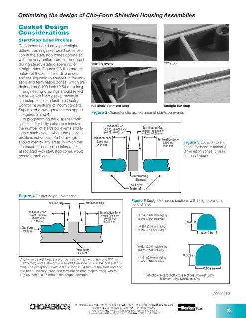
starting event<br />
full circle perimeter stop<br />
“T” stop<br />
straight run stop<br />
Figure 2 Characteristic appearance of start/stop events<br />
Initiation Gap<br />
Termination Gap<br />
+0.030, –0.000 inch<br />
+0.060, –0.000 inch<br />
(+0.76, –0.00 mm) (+1.52, –0.00 mm)<br />
Initiation Zone<br />
0.100 inch<br />
(2.54 mm)<br />
Termination Zone<br />
0.100 inch<br />
(2.54 mm)<br />
Figure 3 Location tolerances<br />
for bead initiation &<br />
termination zones (crosssectional<br />
view)<br />
Figure 4 Gasket height tolerances<br />
Initiation Gap<br />
Termination Gap<br />
Interrupting<br />
Element<br />
Cho-Form<br />
Material<br />
Figure 5 Suggested cross sections with height-to-width<br />
ratio of 0.85<br />
Cho-Form<br />
Material<br />
Initiation Zone<br />
Height Tolerance<br />
±0.006 inch<br />
(±0.15 mm)<br />
Termination Zone<br />
Height Tolerance<br />
±0.006 inch<br />
(±0.15 mm)<br />
0.034 ±0.004 inch high by<br />
0.040 ±0.004 inch wide<br />
(0.864 ±0.10 mm high by<br />
1.016 ±0.10 mm wide)<br />
0.034 in.<br />
0.040 in.<br />
Interrupting<br />
Element<br />
Cho-Form gasket beads are dispensed with an accuracy of 0.001 inch<br />
(0.025 mm) and a straight-run height tolerance of ±0.004 inch (±0.10<br />
mm). The exception is within 0.100 inch (2.54 mm) at the start and end<br />
of a bead (initiation zone and termination zone respectively), where<br />
±0.006 inch (±0.15 mm) is the height tolerance.<br />
0.052 ±0.004 inch high by<br />
0.062 ±0.004 inch wide<br />
(1.321 ±0.10 mm high by<br />
1.575 ±0.10 mm wide)<br />
0.052 in.<br />
0.062 in.<br />
Deflection range for both cross sections: Nominal: 30%,<br />
Minimum: 10%, Maximum: 50%<br />
continued<br />
US Headquarters TEL +(1) 781-935-4850 FAX +(1) 781-933-4318 • www.chomerics.com<br />
Europe TEL +(44) 1628 404000 FAX +(44) 1628 404090<br />
Asia Pacific TEL +(852) 2 428 8008 FAX +(852) 2 423 8253<br />
South America TEL +(55) 11 3917 1099 FAX +(55) 11 3917 0817<br />
23