MENDOTA GAS DIRECT VENT FIREPLACE
MENDOTA GAS DIRECT VENT FIREPLACE
MENDOTA GAS DIRECT VENT FIREPLACE

Create successful ePaper yourself
Turn your PDF publications into a flip-book with our unique Google optimized e-Paper software.
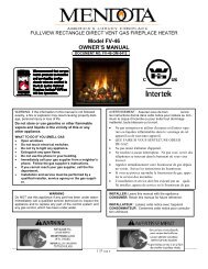
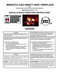
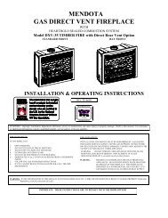
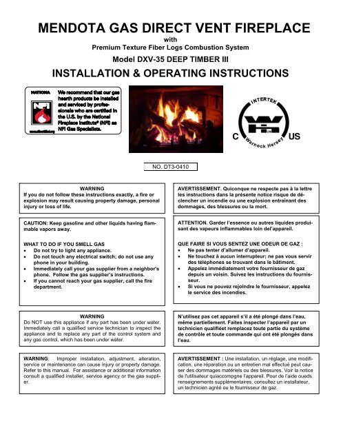
<strong>MENDOTA</strong> <strong>GAS</strong> <strong>DIRECT</strong> <strong>VENT</strong> <strong>FIREPLACE</strong><br />
with<br />
Premium Texture Fiber Logs Combustion System<br />
Model DXV-35 DEEP TIMBER III<br />
INSTALLATION & OPERATING INSTRUCTIONS<br />
NO. DT3-0410<br />
WARNING<br />
If you do not follow these instructions exactly, a fire or<br />
explosion may result causing property damage, personal<br />
injury or loss of life.<br />
AVERTISSEMENT. Quiconque ne respecte pas à la lettre<br />
les instructions dans la présente notice risque de déclencher<br />
un incendie ou une explosion entraînant des<br />
dommages, des blessures ou la mort.<br />
CAUTION: Keep gasoline and other liquids having flammable<br />
vapors away.<br />
ATTENTION. Garder l’essence ou autres liquides produisant<br />
des vapeurs inflammables loin del’appareil.<br />
WHAT TO DO IF YOU SMELL <strong>GAS</strong><br />
• Do not try to light any appliance.<br />
• Do not touch any electrical switch; do not use any<br />
phone in your building.<br />
• Immediately call your gas supplier from a neighbor's<br />
phone. Follow the gas supplier’s instructions.<br />
• If you cannot reach your gas supplier, call the fire<br />
department.<br />
QUE FAIRE SI VOUS SENTEZ UNE ODEUR DE GAZ :<br />
• Ne pas tenter d’allumer d’appareil.<br />
• Ne touchez à aucun interrupteur; ne pas vous servir<br />
des téléphones se trouvant dans le bâtiment.<br />
• Appelez immédiatement votre fournisseur de gaz<br />
depuis un voisin. Suivez les instructions du fournisseur.<br />
• Si vous ne pouvez rejoindre le fournisseur, appelez<br />
le service des incendies.<br />
WARNING<br />
Do NOT use this appliance if any part has been under water.<br />
Immediately call a qualified service technician to inspect the<br />
appliance and to replace any part of the control system and<br />
any gas control, which has been under water.<br />
N’utilisez pas cet appareil s’il a été plongé dans l’eau,<br />
même partiellement. Faites inspecter l’appareil par un<br />
technicien qualifiéet remplacez toute partie du système<br />
de contrôle et toute commande qui ont été plongés dans<br />
l’eau.<br />
WARNING: Improper installation, adjustment, alteration,<br />
service or maintenance can cause injury or property damage.<br />
Refer to this manual. For assistance or additional information<br />
consult a qualified installer, service agency or the gas supplier.<br />
AVERTISSEMENT : Une installation, un réglage, une modification,<br />
une réparation ou un entretien mal effectué peut causer<br />
des dommages matériels ou des blessures. Voir la notice<br />
de l'utilisateur quiaccompgne l’appareil. Pour de l’aide oueds<br />
renseignements supplémentaires, consultez un installateur,<br />
un technicien agréé ou le fournisseur de gaz.
FOR YOUR SAFETY READ BEFORE LIGHTING<br />
POUR PLUS DE SÉCURITÉ, LIRE AVANTD'ALLUMER<br />
WARNING<br />
Do not operate this appliance with the glass removed,<br />
cracked or broken. A licensed or qualified person<br />
should do replacement of glass.<br />
Attention. Ne pas utiliser l’appareil si le panneau frontal<br />
en verre n’est pas enplace, est craqué ou brisé.<br />
Confiez leremplacement du panneau à untechnicien<br />
agréé.<br />
This appliance must be installed in accordance with<br />
local codes, if any; if none, follow the National Fuel<br />
Gas Code, ANSI Z223.1, or Canadian Installation<br />
Codes, CAN/CGA-B149. Gas and Propane Installation<br />
Code, CSA B149.1<br />
Installer l'appareil selon les codes ou règlements locaux,<br />
ou, en l'absence dételés règlements, selon les<br />
codes d'installation ANSI Z223.1, National Fuel Gas<br />
Code ou CAN/CGA-B149 en vigueur.<br />
This appliance is only for use with the type(s) of gas<br />
indicated on the rating plate and may be installed in an<br />
aftermarket, permanently located, manufactured home<br />
(USA only) or mobile home, where not prohibited by<br />
local codes. See owner's manual for details. This appliance<br />
is supplied with a conversion kit.<br />
Cet appareil doit être utilisé uniquement avec le type<br />
de gaz indiqué sur la plaque signalétique. Cet appareil<br />
peut être installé dans une maison préfabriquée ou<br />
mobile (É.-U. seulement) installée à demeure si les<br />
règlements locaux le permettent. Voir la notice de l'utilisateur<br />
pour plus de renseignements. Cet appareil ne<br />
peut pas être utilisé avecd'autres gaz sauf si une<br />
trousse deconversion certifiée est fournie.<br />
Caution: Label all wires prior to disconnection<br />
when servicing controls. Wiring errors can cause<br />
improper and dangerous operation.<br />
In the Commonwealth of Massachusetts:<br />
• Installation must be performed by a licensed<br />
plumber or gas fitter;<br />
• A CO detector shall be installed in the room where<br />
the appliance is installed.<br />
Attention. Au moment de l’entretiennes commandes,<br />
étiquetez tous les fil savant de les débrancher.<br />
Des erreurs decâblage peuvent<br />
entraîner unfonctionnement inadéquat etdangereux.<br />
CAUTION<br />
THESE INSTRUCTIONS ARE TO REMAIN WITH<br />
THE HOMEOWNER.
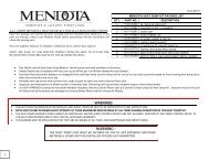
DXV35 DT3 FEATURES - QUICK REFERENCE INFORMATION<br />
EXTERNAL DIMENSIONS: 35-7/8” Wide X 31-1/2” High X 15-1/2” Deep<br />
MINIMUM FRAMING DIMENSIONS: 37-1/8” WIDE x 31-1/2” HIGH X 16” DEEP<br />
GLASS SIZE: NeoCeram Glass with non-reflective coating. Visible Glass measures 456 in 2 . Actual Glass size is 580 in 2 .<br />
MANTEL ALLOWANCE: 8” Deep Mantel at 14” Above Top Convection Opening<br />
<strong>VENT</strong> SYSTEM ALLOWANCE: Top Vent Only. 12” Vertical Minimum with 6” max horizontal. 55 feet Vertical Maximum.<br />
4” exhaust and 6-5/8” combustion air intake coaxial vent pipe required. 12’ maximum horizontal run allowed with 4’ minimum<br />
vertical starter section.<br />
<strong>VENT</strong> DAMPER ADJUSTMENT AVAILABLE: There is one exhaust vent damper included in this unit and located in the<br />
top convection chamber at the center.<br />
CONTROLS: IPI Electronic Ignition System with AC Primary Power and DC Backup Power. Accent light and Blowers operate<br />
on AC Power only.<br />
BLOWER SYSTEM: 210 CFM Dual Blower System. 120VAC, 2Amps. Dedicated Hot Power only. No switches, Fan<br />
Speed Controls or Light Dimmers are allowed in same circuit.<br />
Accent Light System: Accent Light System Included. Light can be turned on or off or dimmed using dimmer mounted<br />
behind lower grill.<br />
BURNER SYSTEM: Dual 304 Stainless Steel Tubular burners.<br />
BURNER AIR SHUTTER SYSTEMS: Externally controllable Rear Burner air shutter and Internal rotary Front Burner air<br />
shutter.<br />
LOG SET: 9-piece, Premium Definition Log Set with Extreme glow and realism ember bed.<br />
REFRACTORY PANELS: High Detail Red Clinker Fiber Brick Panels included. Brick Panels required for operation.<br />
NATURAL <strong>GAS</strong> INFORMATION: Factory equipped for Natural Gas. 4.5”WC Minimum inlet pressure required. For NG<br />
applications, Front Burner Orifice Size is #49 and the Rear Burner Orifice Size is #44.<br />
LPG INFORMATION: LP conversion kit #HA-30-00501 is required. 12”WC Minimum inlet pressure required. For the<br />
DXV35 DT3 LPG application, both front are rear burner orifices are to be drill size 3/64”. For higher altitude, adjustment to<br />
orifice size may be necessary.<br />
INITIAL STARTUP ADVICE<br />
PAINT CURING CYCLE RECOMMENDATION: It is recommended that you run this Fireplace on maximum flame height,<br />
for 3 cycles of 2 hours ON and 2 hours OFF, initially, to cure the paint.<br />
BLOWER BREAK-IN PERIOD: The integrated blowers in this Insert may exhibit some bearing noise and electrical static<br />
noise during the first few days of operation. This is normal during the break-in period. It is recommended that following the<br />
Paint Curing Cycle, the blowers be run at their maximum speed for two 3-hour periods. The burner flames must be on<br />
during these cycles. The blowers in a few fireplaces may take longer to break-in and may require additional operation<br />
time before all extraneous noise is eliminated. Please allow adequate operational time for the blowers to break-in before<br />
you contact your dealer for service.<br />
2
TABLE OF CONTENTS<br />
FOR YOUR SAFETY READ BEFORE LIGHTING ................................................................................................................. 1<br />
DXV35 DT3 FEATURES - QUICK REFERENCE INFORMATION .................................................................................... 2<br />
INITIAL STARTUP ADVICE ............................................................................................................................................... 2<br />
SPECIFICATIONS .................................................................................................................................................................. 5<br />
MINIMUM CLEARANCES FROM COMBUSTIBLE CONSTRUCTION .................................................................................. 5<br />
BUILDING PERMIT AND INSTALLATION INSPECTION APPROVAL REQUIREMENTS ................................................... 5<br />
SPECIFIC REQUIREMENTS FOR THE COMMON WEALTH OF MASSACHUSETTS ....................................................... 6<br />
SAFETY AND WARNING INFORMATION ............................................................................................................................. 7<br />
CONGRATULATIONS ............................................................................................................................................................ 8<br />
GENERAL INFORMATION ..................................................................................................................................................... 9<br />
SAFETY AND STRUCTURAL CONCERNS ....................................................................................................................... 9<br />
<strong>VENT</strong>ING REQUIREMENTS .............................................................................................................................................. 9<br />
HEATING PERFORMANCE ............................................................................................................................................... 9<br />
AESTHETIC CONSIDERATIONS ....................................................................................................................................... 9<br />
ELECTRICAL REQUIREMENTS ........................................................................................................................................ 9<br />
<strong>VENT</strong> OPTIONS DISCUSSION ............................................................................................................................................ 10<br />
<strong>GAS</strong> SUPPLY REQUIREMENTS ......................................................................................................................................... 11<br />
<strong>GAS</strong> SUPPLY LINE SIZING .............................................................................................................................................. 11<br />
<strong>GAS</strong> PRESSURE CHECKING REQUIREMENTS ............................................................................................................ 11<br />
<strong>GAS</strong> PRESSURE REQUIREMENTS .................................................................................................................................... 12<br />
<strong>GAS</strong> PRESSURE REQUIREMENTS ................................................................................................................................ 12<br />
EXTERIOR <strong>VENT</strong> LOCATIONS AND RESTRICTIONS ....................................................................................................... 13<br />
GENERAL FLUE <strong>VENT</strong>ING INSTRUCTIONS ..................................................................................................................... 14<br />
<strong>VENT</strong> COMPONENTS "TWIST-LOCK" CONNECTION PROCEDURE ........................................................................... 14<br />
GENERAL INSTALLATION INSTRUCTIONS ...................................................................................................................... 15<br />
SPECIFICATIONS & CLEARANCES ................................................................................................................................... 16<br />
TOP FLUE <strong>VENT</strong>ING COMPONENTS ................................................................................................................................. 17<br />
FLUE <strong>VENT</strong>ING ALLOWANCE CHART ............................................................................................................................... 18<br />
L.P. <strong>GAS</strong> MINIMUM HEIGHT HORIZONTAL TERMINATION ............................................................................................. 19<br />
MINIMUM RISE THROUGH-THE-WALL <strong>VENT</strong>ING: ............................................................................................................ 20<br />
<strong>VENT</strong>ING COMPONENTS LIST ........................................................................................................................................... 21<br />
ELEVATED VERTICAL RISE THROUGH-THE-WALL <strong>VENT</strong>ING ....................................................................................... 22<br />
VERTICAL THROUGH-THE-ROOF <strong>VENT</strong>ING .................................................................................................................... 23<br />
DOOR REMOVAL AND REPLACEMENT ............................................................................................................................ 24<br />
To Remove Glass Frame: ................................................................................................................................................. 24<br />
To Install Glass Frame: ..................................................................................................................................................... 24<br />
GLASS FRAME ASSEMBLY REPAIR AND REPLACEMENT ......................................................................................... 25<br />
TO REPLACE DAMAGED GLASS ................................................................................................................................... 25<br />
DXV-35 DT3 DEEP TIMBER LOG SET INSTALLATION INSTRUCTIONS ......................................................................... 26<br />
INSTALLATION CHECK OFF LIST ...................................................................................................................................... 37<br />
LIGHTING CHECK OFF LIST ............................................................................................................................................... 37<br />
BEFORE YOU BEGIN .......................................................................................................................................................... 38<br />
3
CONTROL PANEL FUNCTIONS IDENTIFICATION ........................................................................................................ 38<br />
“FIRST TIME” LIGHTING INSTRUCTIONS ...................................................................................................................... 39<br />
OPERATING DURING POWER OUTAGES ..................................................................................................................... 39<br />
THERMOSTAT OR REMOTE CONTROL OPERATION .................................................................................................... 40<br />
HOW TO CONNECT A THERMOSTAT OR WALL SWITCH TO THIS <strong>FIREPLACE</strong> ...................................................... 40<br />
BLOWER OPERATION AND WIRING .............................................................................................................................. 41<br />
TROUBLE SHOOTING <strong>MENDOTA</strong> <strong>GAS</strong> DXV <strong>FIREPLACE</strong> ................................................................................................ 42<br />
FLAME ADJUSTMENT ..................................................................................................................................................... 42<br />
CUSTOMER INFORMATION AND TROUBLE-SHOOTING ................................................................................................ 43<br />
OPERATION DURING POWER OUTAGES ..................................................................................................................... 43<br />
MAINTENANCE .................................................................................................................................................................... 44<br />
WIRING SCHEMATICS ........................................................................................................................................................ 45<br />
IGNITION SYSTEM WIRING SCHEMATIC ...................................................................................................................... 45<br />
BLOWER SYSTEM WIRING SCHEMATICNATURAL TO LP <strong>GAS</strong> CONVERSION INSTRUCTIONS ............................ 45<br />
NATURAL TO LP <strong>GAS</strong> CONVERSION INSTRUCTIONS .................................................................................................... 46<br />
ORIFICE SIZES REQUIREMENT: .................................................................................................................................... 46<br />
RECOMMENDED PROCEDURE TO CONVERT THIS <strong>FIREPLACE</strong> TO BURN LPG ..................................................... 46<br />
INSTALLING THE LP PRESSURE REGULATOR ........................................................................................................... 49<br />
LP <strong>GAS</strong> PRESSURE REQUIREMENTS .............................................................................................................................. 50<br />
LPG PROPER INPUT RATES .......................................................................................................................................... 50<br />
LEAK TESTING REQUIREMENTS ................................................................................................................................... 50<br />
PILOT FLAME AND MAIN BURNER RELATIONSHIP VERIFICATION .......................................................................... 50<br />
PILOT FLAME LENGTH ADJUSTMENT .......................................................................................................................... 50<br />
CHECKING FOR NORMAL BURNER (S) IGNITION CHARACTERISTICS .................................................................... 51<br />
ATTACHING LPG CONVERSION LABELS AND HIGH ALTITUDE DERATION LABEL ................................................ 51<br />
REPLACEMENT PARTS ...................................................................................................................................................... 52<br />
<strong>MENDOTA</strong> DESIGNER FRONTS INSTALLATION INFORMATION ................................................................................... 53<br />
INFORMATION SPECIFIC TO THE INSTALLATION OF THE ANDOVER, BENTLEY AND PRAIRIE FRONTS................................ 53<br />
INFORMATION SPECIFIC TO THE INSTALLATION OF MILLENNIA GRILLS, VICTORIA AND TUSCANY FILIGREES ................. 54<br />
INFORMATION SPECIFIC TO THE INSTALLATION OF THE WELLINGTON FIRESCREEN FRONT .............................................. 54<br />
RATING LABEL REPRESENTATION .................................................................................................................................. 55<br />
<strong>MENDOTA</strong> WARRANTY QUALIFICATION & SERVICE REFERENCE FORM .................................................................. 56<br />
<strong>MENDOTA</strong> EXTENDED LIFETIME PROTECTION AND LIMITED WARRANTY ................................................................ 58<br />
4
SPECIFICATIONS<br />
MODEL DXV-35 DT3<br />
INPUT RATES (Btu/Hr) High Fire - Adjustable to - Low Fire<br />
NAT. <strong>GAS</strong> 33,000 10,000<br />
LP <strong>GAS</strong> 33,000 13,000<br />
NOTE: LP CONVERSION KIT #HA-30-00325 MUST BE PURCHASED SEPARATELY TO BURN LPG.<br />
MAIN ORIFICES…REAR BURNER: #44 NAT. <strong>GAS</strong> [3/64” L.P. <strong>GAS</strong>] – FRONT BURNER: #49 NAT. [3/64” LP]<br />
OVERALL EFFICIENCY Exceeds D.O.E. Efficiency Requirements (A.F.U.E.) For Direct Vent Wall Heaters.<br />
78.5% Steady State Efficiency<br />
CO-AXIAL <strong>DIRECT</strong> <strong>VENT</strong> FLUE ... Top Vent: 4" Inner, 6 5/8" Outer<br />
APPROVED <strong>VENT</strong> SYSTEMS: Amerivent, Duravent, Selkirk Metalbestos, Security Chimney and ICC<br />
NET WEIGHT ................................... 185 POUNDS<br />
SAFETY ........................................... AGA CERTIFIED PILOT GENERATOR, MILLIVOLT SYSTEM<br />
ACTIVATED WITH SWITCH, THERMOSTAT OR REMOTE CONTROL.<br />
<strong>GAS</strong> REQUIREMENTS ................... SUPPLY PRESSURE: <strong>GAS</strong> INLET: 3/8" N.P.T.at Gas Valve Entry Point<br />
NAT. <strong>GAS</strong>: 7" W.C. (5" W.C. MIN., 11" W.C. MAX.)<br />
L.P. <strong>GAS</strong>: 12.0" W.C. (12" W.C. MIN., 14" W.C. MAX.)<br />
ELECTRICAL REQUIREMENTS .... 115 VOLT, LESS THAN 2 amps, Un-switched direct power.<br />
MINIMUM CLEARANCES FROM COMBUSTIBLE CONSTRUCTION<br />
Unit to floor 0 in. Unit to enclosure sidewalls 0.5 in.<br />
Unit to enclosure sidewall 0.5 in. Unit top to ceiling 18 in.<br />
Vent to enclosed 1 in. Wall Pass-Through to framing 1 in.<br />
Vent to adjacent sidewall 10 in. Mantle above discharge air opening 14 in.<br />
Certified under ANSI Z21.88 (2005) •CSA 2-33 (2005) “Vented Gas Fireplace Heaters" not for use with solid fuel.<br />
Approved or bedroom installations and mobile homes. UL307B approved for "mobile homes, after first sale of<br />
home, not for recreational vehicles."<br />
Gas appliances must be tested and certified by a nationally recognized testing and certification agency to American<br />
National Standards Institute - ANSI Gas Appliance Safety Standards. The Mendota Gas DXV Fireplace has been<br />
tested and certified by Intertek Testing Services 8431 Murphy Drive, Middleton, WI<br />
Fireplace Includes A Sealed Combustion System, 6-Piece Ceramic Fiber Log Set & Coals, Firebrick Lined Firebox, Neo-<br />
Ceram Glass, Piezo Igniter, Dual Blowers, Aga Certified Safety System, And Wall Thermostat.<br />
Options: Black, Brass, Classic Brass Or Classic Silver Tone Grill Sets, Black Or 24k Gold "Victoria" & “Tuscany” Filigree<br />
Fronts, Bentley Arched Doors, Andover Arched Doors & 4 Color Overlay Fronts, Prairie Rectangular Doors & 4 Color<br />
Overlay Fronts, Deerfield Front, Wellington Front, Versiheat Remote Forced Air Heat Transfer System, Versiheat II<br />
Forced Air Heat Transfer System, Thermostats, Remote Control Kits.<br />
Building Permit and Installation Inspection Approval Requirements<br />
All installations of Mendota Fireplaces and Inserts must comply with all<br />
the requirements stated in this Installation and Operating Instructions<br />
Manual. The Dealer and/or installer must also obtain all required Building<br />
Permits and Inspection Approval from the local building inspection department<br />
or the local body having jurisdiction. In order to validate warranty<br />
coverage, Mendota may require facsimile copies of the Building Permit<br />
and Inspection Approval forms. Failure to provide adequate proof that<br />
the installation conforms to all local requirements and the requirements<br />
stated in the Installation and Operating Instructions Manual will void all<br />
applicable warranty.<br />
INSTALLER: THESE INSTRUCTIONS ARE TO REMAIN WITH HOMEOWNER.<br />
5
Specific Requirements for the Common Wealth of Massachusetts<br />
The information in this section applies to all installations performed in the Common Wealth of Massachusetts only.<br />
a) For all side wall horizontally vented gas fueled equipment installed in every dwelling, building or structure<br />
used in whole or in part for residential purposes and where the side wall exhaust vent termination is less than<br />
seven (7) feet above grade, the following requirements shall be satisfied:<br />
1. If there is no carbon monoxide detector with an alarm already installed in compliance with the most current<br />
edition of NFPA 720, NFPA 70 and the Massachusetts State Building code in the residential unit<br />
served by the side wall horizontally vented gas fueled equipment, a battery operated carbon monoxide<br />
detector with an alarm shall be installed in compliance with the most current edition of NFPA 720. NFPA<br />
70 and the Massachusetts State Building Code.<br />
2. In addition to the above requirements, if there is not one already present, a carbon monoxide detector<br />
with an alarm and a battery backup shall be installed and located in accordance with the installation requirements<br />
supplied with the detector on the floor level where the gas equipment is installed. The carbon<br />
monoxide detector with an alarm shall comply with 527 CMR, ANSI/UL 2034 Standards or CSA 6.19 and<br />
the most current edition of NFPA 720. In the event that the requirements of this subdivision cannot be<br />
met at the time of the completion of the installation of the equipment, the installer shall have a period of<br />
thirty (30) days to comply with this requirement; provided, however, that during said thirty (30) day period,<br />
a battery operated carbon monoxide detector with an alarm shall be installed in compliance with the most<br />
current edition of NFPA 720, NFPA 70 and the Massachusetts State Building Code. In the event that the<br />
side wall horizontally vented gas fueled equipment is installed in a crawl space or an attic, the carbon<br />
monoxide detector may be installed on the next adjacent habitable floor level. Such detector may be a<br />
battery operated carbon monoxide detector with an alarm and shall be installed in compliance with the<br />
most current edition of NFPA 720, NFPA 70 and the Massachusetts State Building Code.<br />
3. A metal or plastic identification plate shall be permanently mounted to the exterior of the building at a minimum<br />
height of eight (8) feet above grade directly in line with the exhaust vent terminal for the horizontally<br />
vented gas fueled heating appliance or equipment. The sign shall read, in print size no less than one-half<br />
(1/2) inch in size, “<strong>GAS</strong> <strong>VENT</strong> <strong>DIRECT</strong>LY BELOW, KEEP CLEAR OF ALL OBSTRUCTIONS”<br />
4. A final inspection by the state or local gas inspector of the side wall horizontally vented equipment shall<br />
not be performed until proof is provided that the state or local electrical inspector having jurisdiction has<br />
granted a permit for installation of carbon monoxide detectors and alarms as required above.<br />
(b) EXEMPTIONS: The following equipment is exempt from 248 CMR 5.08(2) (a) 1 through 4:<br />
(c)<br />
(e)<br />
1. The equipment listed in Chapter 10 entitled “Equipment Not Required To Be Vented” in the most current<br />
edition of NFPA 54 as adopted by the Board; and<br />
2. Product Approved side wall horizontally vented gas fueled equipment installed in a room or structure separate<br />
from the dwelling, building or structure used in whole or in part for residential purposes.<br />
When the manufacturer of Product Approved side wall horizontally vented gas equipment provides a venting<br />
system design or venting system components with the equipment, the instructions for installation of the<br />
equipment and the venting system shall include:<br />
1. A complete parts list for the venting system design or venting system; and<br />
2. Detailed instructions for the installation of the venting system design or the venting system components.<br />
(d) When the manufacturer of a Product Approved side wall horizontally vented gas fueled equipment does not<br />
provide the parts for venting the flue gases, but identifies “special venting systems”, the following shall be satisfied:<br />
1. The referenced “special venting system” instructions shall be included with the appliance or equipment installation<br />
instructions; and<br />
2. The “special venting systems” shall be Product Approved by the Board, and the instructions for that system<br />
shall include a parts list and detailed installation instructions.<br />
A copy of all installation instructions for all Product Approved side wall horizontally vented gas fueled equipment,<br />
all venting instructions, all parts lists for venting instructions, and/or all venting design instructions shall<br />
remain with the appliance or equipment at the completion of the installation.<br />
6
SAFETY AND WARNING INFORMATION<br />
READ and UNDERSTAND all instructions carefully before starting the appliance. FAILURE TO FOLLOW these instructions<br />
may result in a possible fire hazard and will void the warranty.<br />
Any safety screen or guard removed for servicing must be replaced before operating this appliance.<br />
DO NOT USE this appliance if any part has been under water. Immediately CALL a qualified service technician to inspect<br />
the appliance and to replace any part of the control system and any gas control, which has been underwater.<br />
THIS UNIT IS NOT FOR USE WITH SOLID FUEL.<br />
Installation and repair should be PERFORMED by a qualified service person. The appliance and venting system should<br />
be INSPECTED before initial use and at least annually by a professional service person. More frequent cleaning may be<br />
required due to excessive lint from carpeting, bedding, material, etc. It is IMPERATIVE that the unit’s control compartment,<br />
burners, and circulating air passageways ARE KEPT CLEAN to provide for adequate combustion and ventilation<br />
air.<br />
Always KEEP the appliance clear and free from combustible materials, gasoline, and other flammable vapors and liquids.<br />
NEVER OBSTRUCT the flow of combustion and ventilation air. Keep the front of the appliance CLEAR of all obstacles<br />
and materials for servicing and proper operation.<br />
Due to high temperature, the appliance should be LOCATED out of traffic areas and away from furniture and draperies.<br />
Clothing or flammable material SHOULD NOT BE PLACED on or near the appliance.<br />
Children and adults should be ALERTED to the hazards of high surface temperature and should STAY AWAY to avoid<br />
burns or clothing ignition. Young children should be CAREFULLY SUPERVISED when they are in the same room as the<br />
appliance.<br />
These units MUST use one of the vent systems described in the Installing Your Fireplace section of the Installers Guide.<br />
NO OTHER vent systems or components MAY BE USED.<br />
This gas fireplace and vent assembly MUST be vented directly to the outside and MUST NEVER be attached to a chimney<br />
serving a separate solid fuel-burning appliance. Each gas appliance MUST USE a separate vent system. Common<br />
vent systems are PROHIBITED.<br />
If the vent-air intake system is disassembled for any reason, reinstall per the instructions provided for the initial installation.<br />
The vent system assembly for this fireplace must be periodically examined by a qualified service agency.<br />
INSPECT the external vent cap on regular basis to make sure that no debris is interfering with the airflow. The flow of<br />
combustion and ventilation air not to be obstructed<br />
DO NOT abuse the glass door by striking the glass, slamming the door shut, etc.<br />
Use only authorized parts and materials obtained from Johnson Gas Appliance Company when replacing defective or<br />
damaged glass.<br />
DO NOT USE abrasive cleaners on the glass door assembly. DO NOT ATTEMPT to clean the glass door when it is hot.<br />
Turn off the gas before servicing this appliance. It is recommended that a qualified service technician perform an appliance<br />
check-up at the beginning of each heating season.<br />
DO NOT place furniture or any other combustible household objects within 36 inches of the fireplace front.<br />
CAUTION: Do not operate the appliance with glass removed, cracked or broken. Replacement of the panel(s) should be<br />
done by a licensed or qualified service person.<br />
7
CONGRATULATIONS<br />
You are the owner of a world-class heat producing gas direct vent sealed combustion fireplace.<br />
This elegant, highly efficient Fireplace will be a constant source of comfort and fascination. It will be the focal point of<br />
beauty and interest in your home.<br />
The Mendota Gas Fireplace is a true heating appliance incorporating the traditional aesthetics of fireplace fire viewing<br />
with the controllability and fuel efficiency of a home gas furnace. Of particular interest is the low fuel consumption and brilliant<br />
fire viewing afforded by the realistic Premium Fiber wood fire-like combustion system.<br />
Carefully read the following instructions prior to actual installation. Proper Mendota Gas Fireplace installation and operation<br />
will give you years of safe, trouble free comfort and enjoyment.<br />
If you have any questions regarding installation or operation of your Mendota Fireplace please contact your local dealer.<br />
CAUTION<br />
Due to high temperatures, the Fireplace should be located out of traffic and away from furniture and draperies. Children<br />
and adults should be alerted to the hazards of high surface temperature and should stay away to avoid burns or clothing<br />
ignition. Young children should be carefully supervised when they are in the same room as the Mendota Gas Fireplace.<br />
Clothing or other flammable material should not be placed on or near the Fireplace.<br />
Any safety screen or guard removed for servicing an appliance must be replaced prior to operating this appliance.<br />
The Mendota Gas Fireplace is a powerful and efficient heating unit. It has been designed as a major source of supplemental<br />
heat. As with any mechanical appliance there can be component shut downs. It is advisable to have an alternate<br />
heat supply.<br />
Installation, repair and any adjustments to logs or burner must be done by a qualified service person. The appliance<br />
should be inspected before use and at least annually by a professional service person. More frequent cleaning may be<br />
required due to excessive lint from carpeting, bedding material, carbon build-up, etc. It is imperative that control compartments,<br />
burners and circulating air passageways of the appliance be kept clean. The burner and pilot flames and logs<br />
should be visually checked periodically.<br />
DO NOT use this appliance if any part has been under water or exposed to moisture corrosion. Immediately call a qualified<br />
service technician to inspect the Fireplace and replace any part of the control system and any gas control, which has<br />
been under water. DO NOT use this fireplace if the burner does not light immediately. Turn unit off and call Mendota approved<br />
service person if there is any delay in burner light off.<br />
It is Johnson Gas Appliance Company's policy that no responsibility is assumed by the Company or by any of its employees<br />
or representatives for any damages caused by an inoperable, inadequate, or unsafe condition which is the result,<br />
either directly or indirectly, of any improper operation, installation or servicing procedures.<br />
Building Permit and Installation Inspection Approval Requirements<br />
All installations of Mendota Fireplaces and Inserts must comply with all the requirements stated in this Installation and<br />
Operating Instructions Manual. The Dealer and/or installer must also obtain all required Building Permits and Inspection<br />
Approval from the local building inspection department or the local body having jurisdiction. In order to validate warranty<br />
coverage, Mendota may require facsimile copies of the Building Permit and Inspection Approval forms. Failure to provide<br />
adequate proof that the installation conforms to all local requirements and the requirements stated in the Installation and<br />
Operating Instructions Manual will void all applicable warranty.<br />
INSTALLER: THESE INSTRUCTIONS ARE TO REMAIN WITH HOMEOWNER.<br />
HIGH ALTITUDE INSTALLATION INFORMATION: Prior to installing at altitudes higher than 7500, please contact<br />
the Mendota technical service department for specific venting requirements and venting restrictions.<br />
8
GENERAL INFORMATION<br />
Your Mendota Gas Fireplace has a state-of-the-art co-axial direct vent, sealed combustion system. This advanced, highly<br />
efficient system brings in outside air for combustion and efficiently heats and re-circulates room air. The Mendota system<br />
maintains high air quality, maximizes efficiency and assures proper operation in today's "tight" homes.<br />
SAFETY AND STRUCTURAL CONCERNS<br />
This Fireplace must be installed and serviced by a Mendota approved service person. Any adjustments to burner, pilot,<br />
logs or coal bed must be made by a Mendota approved service person. If pilot goes out always wait five (5) minutes before<br />
relighting pilot. ALWAYS!<br />
<strong>VENT</strong>ING REQUIREMENTS<br />
This Mendota Fireplace can be vented using AMERI<strong>VENT</strong>, DURA<strong>VENT</strong>, SELKIRK METALBESTOS, SECURITY<br />
CHIMNEY and ICC brands of coaxial pipe off the top. Use only Mendota specified vents and vent caps when installing<br />
your fireplace. Closely follow venting locations, directions and requirements. Observe the restrictions relating to vent position<br />
on exterior of home (see PG. 13). Be sure all vent pipe sections are fully twist-locked and leak-proof. Be sure Milpak<br />
Sealant is used on the inner pipe joints of all Simpson DuraVent pipe components and all adjustable pipe sections<br />
manufactured by Simpson DuraVent and American Metals.<br />
REMOVE THE GLASS WHEN LIGHTING THE PILOT FOR THE FIRST TIME. The burners must light immediately & the<br />
flame must travel promptly and smoothly around "curves" and light entire burner. The flame must not "lift" off burners.<br />
DO NOT operate unit if burner does not light immediately or if flame lifts off burner.<br />
This Mendota Direct Vent Fireplace may be placed within inches of adjacent sidewalls. (See Figure 4: Specifications &<br />
Clearances). The fireplace may be placed directly on concrete or wood flooring. If the appliance is to be installed on<br />
carpeting, vinyl or other combustible material other than wood flooring, the appliance shall be installed on a metal or wood<br />
panel extending the full width and depth of the appliance. Combustible mantels may be installed above top of the heat<br />
outlet grills. How far out the mantel may protrude past the front face of this appliance is dependent on the distance from<br />
upper grill. See Figure 4: Specifications & Clearances. Non-combustible (marble, brick, stone, etc.) mantels or mantels<br />
with steel protector plate on underside can be installed at any desired height above upper grill.<br />
Never block upper or lower grills. Always use Mendota grills and Mendota approved vent systems and vent caps.<br />
A non-combustible hearth protector is required and must extend a minimum of 12" in front of the fireplace. If<br />
fireplace is raised off floor 6" or more, no hearth protector is required.<br />
HEATING PERFORMANCE<br />
Mendota Gas Built-in Fireplaces are true, high efficiency gas heaters. With its high heat output the Mendota Fireplace will<br />
heat a large area of your home if situated to maximize heat circulation. Air movement options for maximizing heat circulation,<br />
which can be considered, are through-the-wall grills or floor grills, the continuous operation of central heating furnace<br />
blowers, or ceiling fan. The most efficient method for overall heat distribution is a ceiling fan. The heat output of<br />
the Fireplace can be reduced by up to 23,000 BTUH by slowly turning the Hi/Lo temperature knob on the gas valve counter<br />
clockwise from "Hi" to "Lo" and also turning OFF the rear burner using the Rear Burner ON/OFF Switch. Blower can<br />
also be turned down to reduce heat output.<br />
AESTHETIC CONSIDERATIONS<br />
Burning or static fireplaces are a major aesthetic focus in any room. Locate your gas fireplace as you would a television<br />
set. The Mendota Hearth Gas Fireplace will be a continuing source of comfort and fascination. Corner installations will<br />
afford you the greatest potential for viewing in many rooms.<br />
We suggest installing the Mendota Fireplace 6 to 12 inches above the floor by utilizing an elevated hearth.<br />
ELECTRICAL REQUIREMENTS<br />
A 115-volt electrical service must be supplied at the fireplace location at the time of installation. It must be electrically<br />
grounded in accordance with local codes or in their absence with current edition of the National Electric Code ANSI/NFPA<br />
70. Electrical Service may enter this appliance at the Left Side Junction Box or the Right Side Junction box. The Two integrated<br />
junction boxes are internally wired at the factory. Do not disconnect factory installed wiring at either junction box.<br />
Power supply to blower must be continuous. DO NOT use switches or speed control devices in power supplied to fireplace.<br />
The blower on this appliance is equipped with a three-prong plug for protection against shock hazard and should be<br />
plugged directly into the grounded three-prong receptacle provided with the fireplace. Do not cut or remove the grounding<br />
prong from the plug. NOTE: The blower output can be adjusted with the rheostat. There will be delays in blower operation<br />
during "heat-up" (approx. 15 min.) and extended blower operation during "cool-down" (approx. ½ hr.) of unit.<br />
Thermostat wire may be connected to this appliance. Use only a Millivolt Rated thermostat (Standard or Set-back type).<br />
Thermostat wire is to be run from desired thermostat location to the Main Burner Switch (located behind Courtesy Panel).<br />
See Page 39.<br />
9
<strong>VENT</strong> OPTIONS DISCUSSION<br />
This Mendota Fireplace can be vented using AMERI<strong>VENT</strong>, DURA<strong>VENT</strong>, SELKIRK METALBESTOS, SECURITY<br />
CHIMNEY and ICC brands of coaxial pipe off the top. Use only Mendota specified vents and vent caps when installing<br />
your fireplace. Closely follow venting locations, directions and requirements provided in this Manual. Observe the restrictions<br />
related to vent position on exterior of home (see PG.13).<br />
Make certain that all vent pipe sections are fully twist-locked and leak-proof. Note: When using Dura-vent pipes it is recommended<br />
that you use a silicate stove masonry sealant [Milpak Sealant #65-06-00909] on all inner pipe joints. On the<br />
exterior (air intake) pipe joints, high temperature foil tape may be used instead of the masonry sealant. Contact your<br />
dealer to obtain this sealant material.<br />
TOP <strong>VENT</strong>ING<br />
The DXV-35 Fireplace comes from the factory configured for venting off the top using 4” x 6-5/8” Coaxial Vent Pipes.<br />
AMERI<strong>VENT</strong>, DURA<strong>VENT</strong>, SELKIRK METALBESTOS, SECURITY CHIMNEY and ICC brand pipes and venting components<br />
may be used when venting off the top.<br />
Venting off the top on the DXV-35 Fireplace provides a large degree of flexibility for many venting configurations. However,<br />
a few critical limitations must be understood and adhered to.<br />
Limitation 1: A 12” minimum vertical pipe section must be connected to the top starter collar of the DXV-35. With the<br />
12” vertical section connected, you may only install one 90-degree elbow and a run a maximum 6” horizontal<br />
pipe section before connecting the horizontal vent cap.<br />
Limitation 2: The maximum horizontal run allowed when venting off the top is 12 feet preceded by a minimum 4 feet<br />
vertical run. This 12 feet horizontal run can only be used if a straight vertical run of 48 inches (4 feet) is<br />
connected directly to the top of the dxv35. Do not exceed the maximum 12 feet horizontal run. Even if<br />
the vertical section you installed is greater than 4 feet, do not exceed the 12 feet maximum horizontal<br />
run throughout the entire vent system<br />
10
<strong>GAS</strong> SUPPLY REQUIREMENTS<br />
Correct gas pressure and proper gas supply line sizing is imperative to the successful performance of your Mendota gas<br />
fireplace. Be sure the gas supplier or plumber carefully checks for correct gas pressure and gas line sizing when installing<br />
the fireplace.<br />
It is critical to carefully check for gas leaks when hooking up the fireplace -- check with soap & water solution.<br />
Be sure to install "approved" flex gas line with brass-to-brass fittings to prevent gas leaks at connections.<br />
Gas supply piping must include a drip leg to eliminate the possibility of contaminants entering the gas train.<br />
Adhere strictly to local and national codes for entire installation.<br />
<strong>GAS</strong> SUPPLY LINE SIZING<br />
The Mendota Gas Fireplace comes equipped with a 12” flexible connector kit including a manual shutoff ball valve. Gas<br />
supply piping must enter the Fireplace cabinet from the right side.<br />
The included manual shut-off valve meets Federal Codes. I required by local codes, install an additional manual shutoff<br />
valve upstream of the fireplace’s manual shutoff valve. The appliance and its individual shut-off valve must be disconnected<br />
from the gas supply piping system during any pressure testing of that system at test pressures in excess of ½<br />
PSIG (3.5 kPa).<br />
The appliance must be isolated from the gas supply piping system by closing its individual manual shut-off valve during<br />
any pressure testing of the gas supply piping system at test pressures equal to or less than 1/2 PSIG (3.5 kPa).<br />
A proper gas line diameter must be selected to run from the supply regulator to the Fireplace. Refer to the following table<br />
for proper gas pipe diameters. Strictly adhere to the correct pipe sizes. If in doubt, use the next larger size.<br />
PIPE LENGTH<br />
(FEET)<br />
SCHEDULE 40 PIPE<br />
INSIDE DIA.<br />
TUBING, TYPE L<br />
OUTSIDE DIA.<br />
NAT. L.P. NAT. L.P.<br />
0-10 1/2" (1.3 cm) 3/8" (1.0 cm) 1/2" (1.3 cm) 3/8" (1.0 cm)<br />
10-40 1/2" (1.3 cm) 1/2" (1.3 cm) 5/8" (1.6 cm) 1/2" (1.3 cm)<br />
40-100 1/2" (1.3 cm) 1/2" (1.3 cm) 3/4" (2.0 cm) 1/2" (1.3 cm)<br />
100-150 3/4" (2.0 cm) 1/2" (1.3 cm) 7/8" (2.3 cm) 5/8" (1.6 cm)<br />
150-200 3/4" (2.0 cm) 1/2" (1.3 cm) 7/8" (2.3 cm) 3/4" (2.0 cm)<br />
NOTE: Some areas allow copper tubing or galvanized pipe - check with local approval agencies and codes. NEVER use plastic<br />
pipe.<br />
<strong>GAS</strong> PRESSURE CHECKING REQUIREMENTS<br />
Inlet and manifold gas pressure checking taps are located on gas valve (see Figure 1 on Page 10). A qualified installer<br />
should use these fittings for setting the correct gas pressure during initial installation.<br />
NOTE: DO NOT DAMAGE OR KINK THE FLEX CONNECTOR. CHECK FOR <strong>GAS</strong> LEAKS WITH SOAP AND WATER<br />
SOLUTION.<br />
NOTE: 3/8" FLEX OR RIGID PIPING MAY BE USED TO CONNECT <strong>GAS</strong> SUPPLY TO UNIT DEPENDING ON STATE<br />
AND LOCAL CODES.<br />
NOTE: BE SURE TO INSTALL FLEX <strong>GAS</strong> HOSE WITH BRASS-TO-BRASS FITTINGS TO PRE<strong>VENT</strong> LEAKS AT<br />
CONNECTION.<br />
NOTE: THE HARD PLUMBING FITTING PROVIDED IS TO BE USED WITH INSTALLATIONS REQUIRING HARD<br />
PLUMBING. IT MAY BE REMOVED IF THE <strong>FIREPLACE</strong> IS BEING INSTALLED WITH A FLEXIBLE<br />
CONNECTOR.<br />
11
<strong>GAS</strong> PRESSURE REQUIREMENTS<br />
A MAJOR CAUSE OF OPERATING PROBLEMS WITH <strong>GAS</strong> APPLIANCES CAN BE IMPROPER <strong>GAS</strong> PRESSURE!<br />
Problems such as changes in flame color or flame height, pilot or burner outages, intermittent operation,<br />
changes in heat output, excessive burner noise, etc. are nearly always the result of changes in gas pressure or<br />
improper gas pressure at the time of the installation. The most important item to check during the installation<br />
and the first thing to check when problems occur is gas pressure!<br />
Gas supplies normally enter a residence at 1/2 PSI (13" - 15" W.C.) (3. KPA). A regulator is then placed inside<br />
the residence, which drops this pressure to 7" W.C. (1.8 KPA) (Nat. Gas). This "inches to inches" regulator is<br />
of adequate capacity to service the gas appliances (such as dryer, furnace, etc.). If this regulator's capacity is<br />
not sufficient to add the Gas Fireplace, an additional "inches to inches" regulator must be installed for the Fireplace.<br />
EXCEPTION: Some codes allow 2-PSI (1.4KPA) supplies to enter the residence, in which case<br />
"pounds to inches" regulators are used.<br />
The following table provides information on correct gas pressure requirements. Be sure your gas supplier or<br />
plumber carefully follows this table.<br />
<strong>GAS</strong> PRESSURE REQUIREMENTS<br />
DESIRED<br />
INLET<br />
PRESSURE<br />
MINIMUM<br />
INLET<br />
PRESSURE<br />
MAXIMUM<br />
INLET<br />
PRESSURE<br />
MANIFOLD<br />
OUTLET<br />
PRESSURE<br />
AIR SHUTTER<br />
POSITION*<br />
NATURAL <strong>GAS</strong><br />
7.0" W.C.<br />
(1.75 kPa)<br />
5.0" W.C.<br />
(1.12 kPa)<br />
11" W.C.<br />
(2.61 kPa)<br />
3.5" W.C.<br />
(0.87 kPa)<br />
1/16 - 3/16 "<br />
OPEN<br />
L.P. <strong>GAS</strong><br />
12.0" W.C.<br />
(3.00 kPa)<br />
11" W.C.<br />
(2.75 kPa)<br />
13.0" W.C.<br />
(3.24 kPa)<br />
10.0" W.C.<br />
(2.5 kPa)<br />
1/4" OPEN-MIN.<br />
TURN <strong>GAS</strong> VALVE KNOB TO "HIGH" POSITION. <strong>GAS</strong> PRESSURES MAY VARY PLUS OR MINUS 5%.<br />
NOTE: For High Altitude (Above 5.000 Feet) Some Variations In Air Shutter Settings May Be Required.<br />
Manifold pressure must be taken at the Output Pressure tap and inlet pressure at the Inlet Pressure tap with the burner<br />
operating by a qualified installer (see Figure 1: Gas Pressure Test Port).<br />
Figure 1: Gas Pressure Test Ports<br />
OUTLET<br />
PRESSURE<br />
TAP<br />
INLET<br />
PRESSURE<br />
TAP<br />
PRESSURE<br />
REGULATOR<br />
12
EXTERIOR <strong>VENT</strong> LOCATIONS AND RESTRICTIONS<br />
A =<br />
B =<br />
C =<br />
D =<br />
E =<br />
Figure 2: Exterior Vent Locations<br />
ALL MEASUREMENTS GIVEN ARE FROM THE CENTER LINE OF <strong>VENT</strong> CAP<br />
∨ - Vent Terminal ∧ - Air Supply Inlet ≡ - Area where terminal is not permitted<br />
Clearance above grade, veranda, porch, deck, or<br />
balcony (*12 inches (30 cm) minimum). Vinyl surfaces<br />
require 24” min.<br />
Clearance to window or door that may be opened<br />
(*12 inches (30 cm) minimum.<br />
Clearance to permanently closed window (minimum<br />
12 inches (30 cm).<br />
Vertical clearance to ventilated soffit located above<br />
the terminal from the center-line of the terminal (12<br />
inches (30 cm) minimum) Vinyl surfaces require<br />
24” min.<br />
Clearance to unventilated soffit (18 inches (46 cm)<br />
minimum) Vinyl surfaces require 24” min.<br />
H =<br />
I =<br />
J =<br />
*Not to be installed above a meter/regulator assembly<br />
within 3 feet (90 cm) horizontally from the center-line of<br />
the regulator<br />
Clearance to service regulator vent outlet (*6 feet (1.8m)<br />
minimum)<br />
Clearance to non-mechanical air supply inlet to building<br />
or the combustion air inlet to any other appliance.<br />
*12 inches (30 cm) minimum.<br />
K = Clearance to a mechanical air supply inlet (*6 feet (1.8 m)<br />
minimum)<br />
L =<br />
† Clearance above paved side-walk or a paved driveway<br />
located on public property (*7 feet (2.1 m) minimum)<br />
F = Clearance to outside corner - 6 inches (15 cm). M = Clearance under veranda, porch, deck, or balcony (*18<br />
inches (30 cm) minimum ‡)<br />
G = Clearance to inside corner - 12 inches (30 cm).<br />
Vinyl surfaces require 24” min.<br />
N= Minimum 24” horizontal clearance to any surface, such<br />
as an exterior surface, for vertical terminations.<br />
† A vent shall not terminate directly above a sidewalk or paved driveway, which is located between two single-family<br />
dwellings and serves both dwellings.<br />
‡ Only permitted if veranda, porch, deck, or balcony is fully open on a minimum of two sides beneath the floor.<br />
* As specified in CGA B1:19 Installation Codes (1991). Note: Local codes or regulations may require different clearances.<br />
13
GENERAL FLUE <strong>VENT</strong>ING INSTRUCTIONS<br />
The Mendota Fireplace must be vented using Amerivent, Duravent, Selkirk Metalbestos, Security Chimney or ICC Brand<br />
venting systems. All warranties will be voided and serious fire, health or other safety hazards may result from any of the<br />
following actions: Installation by unauthorized personnel; installation of any damaged component; unauthorized modification<br />
of vent system; installation of any components not approved by Mendota; failure to meet all clearance requirements;<br />
failure to properly twist-lock and positively seal all components. Consult local building codes before beginning the installation.<br />
WARNING<br />
Always maintain required clearances (air spaces) to combustibles to prevent a fire hazard. Do not fill air spaces with insulation.<br />
Check installation instructions for minimum clearance requirements between the outer walls of the vent pipe and<br />
nearby combustible surfaces. Be sure to check the vent termination clearance requirements from decks, windows, soffits,<br />
gas regulators, air supply inlets, and public walkways, as specified in these installation instructions and local building<br />
codes. SAFETY PRECAUTIONS FOR THE INSTALLER: 1) Wear gloves and safety glasses for protection; 2) Exercise<br />
extreme caution when using ladders or on rooftops; and 3) be aware of electrical wiring locations in walls and ceilings.<br />
The gas appliance and vent system must be vented directly to the outside of the building, and never attached to a chimney<br />
serving another solid fuel or gas burning appliance. Each direct vent gas appliance must have its own separate vent<br />
system. Common vent systems are prohibited.<br />
To assure proper venting performance of the high-performance Mendota Direct Vent Fireplace, it is critical that all brands<br />
of vent pipe sections are sealed tightly and leak-proof. This means that all pipe sections must be carefully rotated into the<br />
fully "twist-locked" position.<br />
We Strongly Recommend That Fixed Length Pipe Sections Be Used In Place Of Telescoping Sections Whenever<br />
Possible.<br />
Note: When using vent pipe and components that do not incorporate a fiberglass or graphite gasket at the joints, it is recommended<br />
that you use Milpak 1000F silicate stove sealant (#65-06-00909). High temperature foil tape may be used on<br />
the outer (air intake) pipe joints.<br />
DO NOT SEPARATE ADJUSTABLE TELESCOPING SECTIONS. THEY MUST BE USED AS COMPLETE<br />
ASSEMBLIES.<br />
<strong>VENT</strong> COMPONENTS "TWIST-LOCK" CONNECTION PROCEDURE<br />
DuraVent and American Metals pipe and fittings are designed with special twist-lock connections. Twist-lock<br />
procedure is as follows: four (4) indentations, located on the female ends of pipes and fittings are designed to<br />
slide straight in to the male ends of the adjacent pipes and fittings, by orienting<br />
the four pipe identifications so that they match and slide into the four entry<br />
slots on the male ends (Figure 3).<br />
Push the pipe sections completely together then twist-lock one section<br />
clockwise, approximately ¼ turn until the two sections are fully locked. The<br />
female locking lugs will not be visible from the outside on the black pipe or<br />
fittings. They may be located by examining inside of the female ends.<br />
Figure 3: Twist-Lock Piping<br />
14
GENERAL INSTALLATION INSTRUCTIONS<br />
CAUTION: Each installation must conform to all local, state and national codes. Refer to the national fuel gas code and local zoning<br />
and code authorities for details on installation requirements. The Mendota Fireplace must be vented to the outside in accordance with<br />
the latest edition of the National Fuel Gas Code. In the absence of local codes, the installation must conform to the most current edition<br />
of the National Fuel Gas Code ANSI Z223.1, also known as NFPA 54. NOTE: The Mendota DXV Fireplace is approved for mobile<br />
home and bedroom installations.<br />
CAUTION: The Mendota DXV Fireplace may be installed in a manufactured (mobile) home after the first sale of the home. Manufactured<br />
home (mobile home) installation must conform with the Manufactured Home Construction and Safety Standard, Title 24<br />
CFR, Part 3280, or, when such a standard is not applicable, the Standard for Manufactured Home Installations, ANSI A225.1/NFPA<br />
501A, or CSA Z240.4-Gas Equipped Mobile Housing. Consult your local building official. Note: For mobile home installations unit<br />
must be bolted to the floor and properly grounded.<br />
This Fireplace must be installed by a qualified service person.<br />
1. After selection of the desired fireplace location, prepare the rough opening using framing dimensions on PAGE 164.<br />
Be sure to also prepare opening to allow for co-axial vent (see "Flue Venting Instructions".<br />
2. Check to make certain all venting requirements and clearances are being followed.<br />
3. The Fireplace is designed to be installed into rough framing. The drywall will cover the adjustable nailing flanges on<br />
the Fireplace sides. Before sliding the Fireplace into the framed opening, adjust the nailing flanges to accommodate<br />
the thickness of the wall material. NOTE: FRAMING MATERIALS LOCATED ABOVE <strong>FIREPLACE</strong> BODY MUST<br />
MAINTAIN CORRECT CLEARANCES TO <strong>VENT</strong> PIPE.<br />
WARNING<br />
DO NOT COVER THE 2” BLACK FRONT SURFACE OF THIS UNIT IF YOU INTEND TO USE THE ANDOVER,<br />
BENTLEY, DEERFIELD or WELLINGTON TRIMS!!<br />
4. Slide Fireplace into the rough framed opening. When finishing the unit, combustible materials may overlay nailing<br />
flanges and come in contact with the edges of the black front surface, but may not overlap the 2" black front surface.<br />
Noncombustible material, such as marble, stones or brick, can be installed over the 2" black surface, only if<br />
you are certain that a Deerfield Front, Andover Front, Bentley Front, Prairie Front or a Wellington Front is<br />
NOT going to be used as the optional trim, up to the inside edge of black frame (next to glass). ROUGH<br />
FRAMING CAN COME NO CLOSER TO UNIT THAN THE STAND-OFFS.<br />
5. Level the Fireplace and secure into opening by nailing through the nailing flanges on cabinet side panels. Holes<br />
are provided in fireplace floor behind grill to secure fireplace to floor using lag screws or drywall screws, if required.<br />
NOTE: A removable panel in the enclosure for future visual inspection of flue connection is recommended.<br />
6. Have an electrician install a 115-Volt supply to the junction box on lower left side of the fireplace cabinet. Connect<br />
wires to the duplex outlet. This duplex outlet is removable from outside of cabinet for easy wiring. Make sure the<br />
outlet is properly grounded and that the installation conforms to all local and national wiring codes.<br />
7. Have gas supplier or qualified plumber install gas supply line to fireplace and connect to gas nipple. Be sure Gas<br />
Supply Requirements (see PG. 9-10) and all local and national codes are carefully followed.<br />
IMPORTANT: Any safety screen, guard, glass or grills removed for servicing a fireplace/room heater must be replaced<br />
prior to operating the fireplace/room heater.<br />
BLOWER OPERATION<br />
This fireplace is designed so the blower operates continually when the body is of this fireplace is hot and the main<br />
burner(s) are on. The blower output can be regulated with the included blower speed control rheostat. NOTE: There<br />
will be a delay before the blower operates during "heat-up" (approx. 15 minutes) and extended blower operation during<br />
"cool-down" of unit (approx. ½ hour).<br />
OPERATION DURING POWER OUTAGES<br />
The fireplace is designed to operate during power outages for 1-1/2 continuous hours, Maximum. The blower will not<br />
operate, but natural convection can be improved by removing the upper grill and opening the screen doors (depending<br />
on the type of optional front installed). After 1-1/2 continuous hours of operation, during the power outage, turn off the<br />
burners for 1 hour and allow the fireplace to cool down. Consecutive 1-1/2 hour burn and 1 hour cool down cycles are<br />
allowed.<br />
15
<strong>MENDOTA</strong> DXV-35 <strong>GAS</strong> <strong>DIRECT</strong> <strong>VENT</strong> <strong>FIREPLACE</strong><br />
SPECIFICATIONS & CLEARANCES<br />
WARNING: Do not cover the 2” faceplate border of the unit with combustible materials.<br />
26 1/2<br />
37 7/16<br />
6"MIN.<br />
1"MIN.<br />
22 5/16<br />
11 1/8<br />
10 3/4<br />
4 1/2<br />
15 3/8<br />
35 7/8<br />
1/2 TO<br />
2 1/2<br />
52 1/2<br />
16 1/4<br />
45°<br />
10"<br />
MINIMUM FRAMING DIMENSIONS<br />
FOR THIS <strong>FIREPLACE</strong><br />
31-1/2<br />
HEIGHT<br />
(800 mm)<br />
WIDTH<br />
DEPTH<br />
37 1/8<br />
(943 mm)<br />
16<br />
(407 mm)<br />
Adjacent Walls:<br />
A wall, perpendicular to and in front of the appliance front<br />
facing must be at least 10" from the firebox opening. A<br />
wall at 45° to the front and starting at the appliance's<br />
outer edge is permitted. Projections behind this wall (shaded<br />
area) are permitted.<br />
1<br />
2<br />
COMBUSTIBLE MANTEL MUST REMAIN IN THIS<br />
TRIANGULAR AREA. FOR EVERY 1" INCREASE IN<br />
MANTEL DEPTH, INCREASE HEIGHT ABOVE GRILL<br />
BY 2". MANTEL MAY BE LOWERED IF DEPTH IS<br />
DECREASED IN THE SAME MANNER<br />
2" MIN.<br />
8" COMBUSTIBLE MANTEL<br />
8" MANTEL<br />
DEPTH (WIDTH)<br />
36 1/4 TO SCREW HEADS<br />
14<br />
14" MANTEL<br />
HEIGHT FOR<br />
8" MANTEL<br />
1"<br />
MIN.<br />
16 1/4 MIN.<br />
FROM TOP<br />
OF UNIT<br />
TO STACK<br />
CENTER<br />
31 7/16<br />
41<br />
27<br />
28 3/8<br />
32 5/8<br />
16 1/16<br />
1 15/16<br />
IF MANTEL IS MADE OF A NON-COMBUSTIBLE MATERIAL<br />
(BRICK, STONE, ETC..), OR HAS A STEEL PROTECTOR PLATE<br />
ON THE UNDERSIDE IT MAY BE PLACED ANYWHERE ABOVE GRILL<br />
31 11/16<br />
NON-COMBUSTIBLE<br />
HEARTH PROTECTOR<br />
REQUIRED<br />
4 21/32<br />
<strong>GAS</strong> INLET<br />
12<br />
2 7/16<br />
85-03-00458<br />
49 1/2" MIN.<br />
CLEARANCE TO<br />
COMBUSTIBLE<br />
ABOVE UNIT<br />
& MINIMUM<br />
CEILING HEIGHT<br />
NOTE:<br />
FOR EVERY 1" THE <strong>FIREPLACE</strong> IS RAISED OFF THE FLOOR,<br />
HEARTH PROTECTOR MAY BE REDUCED BY 2".<br />
IF <strong>FIREPLACE</strong> IS RAISED 6" OR MORE, NO HEARTH PROTECTION IS REQUIRED.<br />
Figure 4: Specifications & Clearances<br />
NOTE: For L.P. & High Altitude (above 4,000 ft. but below 7500 ft.), 45º elbows must be used in place of 90º elbows.<br />
For Installation At Altitudes Above 7,500 Feet, First Call Mendota Technical Hotline For Further Information On The Strict<br />
Requirements For Installations At These Altitudes.<br />
Using 45 o elbows in place of a 90 o elbow requires 22" minimum opening to center.<br />
CAUTION: If 90ºelbows must be used with LP or at high altitudes, a 3-foot vertical starter section must be used directly<br />
off the top of the fireplace.<br />
16
TOP FLUE <strong>VENT</strong>ING COMPONENTS<br />
ITEM<br />
DESCRIPTION<br />
1 12" <strong>VENT</strong> STACK<br />
1 24" <strong>VENT</strong> STACK<br />
1 36" <strong>VENT</strong> STACK<br />
1 48" <strong>VENT</strong> STACK<br />
2 90ºGALVANIZED ELBOW<br />
3 45º GALVANIZED ELBOW<br />
4 ADJUSTABLE WALL THIMBLE<br />
5 6" or 7” PIPE<br />
9 ATTIC INSULATION SHIELD 12"<br />
10 ROOF FLASHING (0/12 TO 6/12)<br />
10 ROOF FLASHING (7/12 TO 12/12)<br />
11 STORM COLLAR<br />
12 VERTICAL <strong>VENT</strong> CAP<br />
13 SUPPORT BAND<br />
14 HORIZONTAL <strong>VENT</strong> CAP<br />
15 FIRESTOP SPACER<br />
Figure 5: Flue Venting Components<br />
NOTE: DO NOT SEPARATE TELESCOPING SECTIONS. THEY MUST BE USED AS COMPLETE ASSEMBLIES.<br />
17
FLUE <strong>VENT</strong>ING ALLOWANCE CHART<br />
NOTE: FOR LP <strong>GAS</strong> & HIGH ALTITUDE, SEE PG. 19<br />
NOTE: FOR LPG AND HIGH ALTITUDE<br />
APPLICATIONS, SEE PAGE 19.<br />
Figure 6: DXV35 Vertical & Horizontal Vent Requirements<br />
NOTE: 12” MINIMUM VERTICAL PIPE CAN BE USED IF NO HORIZONTAL <strong>VENT</strong> SECTIONS GREATER THAN 6” (or<br />
7”) ARE USED. ALL OTHER INSTALLATIONS MUST FALL WITHIN ABOVE SHADED AREA.<br />
18
L.P. <strong>GAS</strong> MINIMUM HEIGHT HORIZONTAL TERMINATION<br />
L.P. <strong>GAS</strong> OR HIGH ALTITUDE (ABOVE 4,000 FT. BUT BELOW 7500 FT.)<br />
WALL THIMBLE<br />
REQUIRED<br />
6" COAX <strong>VENT</strong><br />
(MIN.)<br />
45° COAX <strong>VENT</strong><br />
TERMINATION CAP<br />
45° COAX <strong>VENT</strong><br />
12" COAX <strong>VENT</strong><br />
(MIN.)<br />
22"<br />
(MIN.)<br />
49 1/4"<br />
(MIN.)<br />
85-03-00531<br />
15 1/2"<br />
Figure 7: LP MINIMUM <strong>VENT</strong><br />
For L.P. gas and high altitude installations (above 4,000 ft.), 45° elbows must be used in place of 90° elbows.<br />
NOTE: This requires 22” minimum height to center of vent cap.<br />
CAUTION: If 90° elbows must be used, a 24 inch vertical starter section must be used off the top of the fireplace.<br />
19
MINIMUM RISE THROUGH-THE-WALL <strong>VENT</strong>ING:<br />
The minimum vertical rise for vent installation through the wall is 16 1/4" from the top of the fireplace to the centerline of<br />
the 90ºelbow in installations where only a 6” (or 7”) horizontal vent section is used (refer to chart on PG.16 when using<br />
horizontal sections). NOTE: We recommend always using the most vertical rise the installation will allow. This maximizes<br />
efficiency and flame appearance. This is especially true for LP gas installations and for installations at higher altitudes.<br />
Use "fixed" pipe sections in place of adjustable pipe sections wherever possible. 1000º sealant use is recommended on<br />
inner pipe joints. Always maintain 1" clearances from vent pipe sides and bottom to combustibles, 3" above pipes on horizontal<br />
runs and above elbows. Do not fill air spaces with insulation or other material.<br />
For L.P. gas and High Altitude (above 4,000 ft.), 45º elbows must be used in place of 90º elbows.<br />
NOTE: This requires 19" minimum rough opening depth (see PG. 15). CAUTION: If 90º elbows must be used, a 3-foot<br />
vertical starter section must be used directly off the top of the fireplace.<br />
THIS <strong>FIREPLACE</strong> MUST BE INSTALLED BY A QUALIFIED <strong>MENDOTA</strong> APPROVED SERVICEPERSON.<br />
IMPORTANT: REFER TO DRAWINGS ON PAGES 14-17 WHILE FOLLOWING THESE INSTRUCTIONS.<br />
1. Position fireplace in desired location. See PG. 11 for guidelines on proper vent cap placement on the exterior of<br />
home. Check to determine if wall studs are in the way when venting system is attached. If this is the case, you may<br />
want to adjust the fireplace location.<br />
2. Measure from the top of the fireplace up minimum (see Figure 4: Specifications & Clearances, PG. 164) and mark<br />
wall directly at the center of where the vent pipe will penetrate the wall.<br />
3. Cut and frame a 9" wide x 10" high rectangle opening in the wall. The hole must be positioned so the vent system will<br />
run level or have a ¼" rise AND be perpendicular to the wall. The height of the opening must be located to meet all<br />
local and national building codes and not allow the termination to be easily blocked or obstructed. If wall being penetrated<br />
is non-combustible material, i.e. masonry block, brick, etc., a 7-inch diameter hole is acceptable.<br />
4. Assemble the components to the fireplace adapter with pipe seams oriented toward the wall or floor -- as much out of<br />
view as possible. Be sure all vent component connections are in their fully twist-locked position and are leak-proof.<br />
Be sure 1000ºsealant is used on the inner pipe joints of all pipe sections manufactured by Simpson DuraVent. American<br />
Metal pipe joints do not require this sealant.<br />
NOTE: DO NOT SEPARATE TELESCOPING SECTIONS. THEY MUST BE USED AS COMPLETE ASSEMBLIES.<br />
5. The length of the horizontal piece that fits through the wall will be determined by the thickness of the wall. When installed,<br />
the end of the horizontal piece must be flush with the exterior wall of the home. There MUST be a minimum<br />
of 1" air space clearance to combustibles from all vent pieces (3" above horizontal runs and on top of elbows).<br />
6. A wall thimble must always be used when penetrating combustible wall materials.<br />
NOTE: Combustible wall thickness must be 4" to 8" maximum for the wall thimble. Wall more than 8” thick will require<br />
special protection. Contact Mendota Technical services for assistance.<br />
7. From the exterior of the home, slide the horizontal vent cap over the end of the horizontal pipe and tightly secure the<br />
cap to the wall with screws. Seal with a high quality caulking.<br />
WARNING: Venting terminal shall never be recessed into wall cladding or siding. Vent Cap must sit on top of siding or<br />
cladding.<br />
20
<strong>VENT</strong>ING COMPONENTS LIST<br />
<strong>MENDOTA</strong> #<br />
DESCRIPTION<br />
45-01-00186 7" LENGTH<br />
45-01-00187 12" LENGTH<br />
45-01-00188 24" LENGTH<br />
45-01-00189 36" LENGTH<br />
45-01-00190 48" LENGTH<br />
45-01-00191 ADJUSTABLE LENGTH<br />
45-01-00192 45 DEG. ELBOW<br />
45-01-00193 90 DEG. ELBOW<br />
45-01-00194 WALL THIMBLE<br />
45-01-00195 VERTICAL CAP<br />
45-01-00196 HORIZONTAL CAP<br />
45-01-00197 14" SNORKEL CAP<br />
45-01-00198 36" SNORKEL CAP<br />
45-01-00199 WALL STRAP<br />
45-01-00200 FIRESTOP SUPPORT PLATE<br />
45-01-00201 FLASHING: 0/12-6/12 PITCH<br />
45-01-00202 FLASHING: 6/12 - 12/12 PITCH<br />
45-01-00203 STORM COLLAR<br />
45-01-00204 ATTIC INSULATION SHIELD<br />
45-01-00206 CO-LINEAR APPLIANCE ADAPTOR<br />
45-01-00207 CO-LINEAR TOP KIT<br />
45-01-00208 VERTICAL KIT<br />
45-01-00209 HORIZONTAL KIT<br />
45-01-00210 HORIZONTAL KIT #2<br />
45-01-00211 7" LENGTH- BLACK<br />
45-01-00212 12" LENGTH - BLACK<br />
45-01-00213 24" LENGTH - BLACK<br />
45-01-00214 36" LENGTH - BLACK<br />
45-01-00215 48" LENGTH - BLACK<br />
45-01-00216 ADJUSTABLE LENGTH - BLACK<br />
45-01-00217 45 DEG. ELBOW - BLACK<br />
45-01-00218 90 DEG. ELBOW - BLACK<br />
45-01-00219 FACEPLATE, CEILING SUPPORT/ WALL THIMBLE - BLK<br />
45-01-00220 ROOF SUPPORT - BLACK<br />
45-01-00224 36" LENGTH<br />
45-01-00225 48" LENGTH<br />
45-01-00226 ADJUSTABLE LENGTH<br />
NOTE: ALL PART NUMBERS LISTED ABOVE APPLY TO SIMPSON DURA<strong>VENT</strong> COMPONENTS ONLY.<br />
21
ELEVATED VERTICAL RISE THROUGH-THE-WALL <strong>VENT</strong>ING<br />
The required MINIMUM vertical rise is 48 in. when used with a maximum horizontal run of 12 ft. For other venting configurations<br />
within these maximum limits, see Figure 6, PG. 18.<br />
NOTE: All horizontal runs of vent pipe must be level or have a ¼" rise for every 1' of run toward the termination.<br />
Never allow the vent to run downward. This will cause high temperatures and the possibility of a fire.<br />
USING OFFSETS AND RETURNS: A single 90º vertical-to-horizontal elbow is already calculated into the allowable<br />
maximum 12' horizontal run. Each additional 90º elbow reduces the maximum horizontal distance by 3'. Example: by<br />
using three total 90º elbows the maximum horizontal distance has been reduced to 6 ft. (3 - 1 = 2 elbows x 3' = 6'; 12’<br />
Max. - 6' of elbows = 6' of horizontal run). Note: 45º elbows reduce the maximum horizontal distance by 1½ '.<br />
SUPPORT: Horizontal runs of pipe will require one vent support for every 3 ft. of pipe.<br />
CAUTION: If a vertical-to-horizontal elbow is enclosed within a wall, floor or ceiling, a top air space clearance of 3" must<br />
be maintained above the elbow. Be sure to maintain 1" air space to any combustibles on the sides and bottom, 2" above<br />
horizontal pipe sections.<br />
THIS <strong>FIREPLACE</strong> MUST BE INSTALLED BY A QUALIFIED <strong>MENDOTA</strong> APPROVED SERVICEPERSON.<br />
IMPORTANT: REFER TO DRAWINGS ON PAGES 14-17 WHILE FOLLOWING THESE INSTRUCTIONS.<br />
1. Position fireplace in desired location. See PG. 13 for guidelines on proper vent cap placement on exterior of<br />
home. Check to determine if wall studs are in the way when vent system is attached. If this is the case you may<br />
want to adjust the fireplace location.<br />
2. Locate the position where vent pipe will pass through any ceilings and will penetrate the outside wall. Since vent<br />
pipe sections "overlap" we suggest pre-assembling and measuring the total vent pipe run so you can more accurately<br />
locate the point where the vent pipe will penetrate the outside wall (See Figure 2: Exterior Vent Locations,<br />
PG. 13). Be sure all vent components are properly twist locked and leak-proof. It is recommended that 1000º<br />
sealant be used in the inner pipe joints of all pipe sections manufactured by Simpson DuraVent.<br />
NOTE: DO NOT SEPARATE TELESCOPING SECTIONS. THEY MUST BE USED AS COMPLETE ASSEMBLIES.<br />
3. Cut and frame a 9-1/2” wide x 10” high openings in the outside wall openings and 9” x 9” opening in ceiling openings.<br />
The outside wall hole must be positioned so the vent system will run level or have a ¼" on rise AND be perpendicular<br />
to the wall. The height of the opening must be located to meet all building codes and not allow the<br />
termination to be easily blocked or obstructed. A ceiling fire stop spacer is required at all floor (ceiling) penetrations.<br />
4. Connect vent pipe to the fireplace adapter on top of fireplace vent outlet.<br />
5. The horizontal pipe must end flush with the exterior wall of the home. Horizontal pipes will require proper support<br />
every 3 ft. of vent pipe. THERE MUST BE A MINIMUM OF 1" CLEARANCE TO COMBUSTIBLES ON THE<br />
SIDES AND BOTTOM OF ALL <strong>VENT</strong> PIECES (3" above horizontal runs and above elbows).<br />
6. A wall thimble must always be used when penetrating combustible wall materials.<br />
NOTE: Combustible wall thickness must be 4" to 8" maximum for the wall thimble. Wall more than 8” thick will<br />
require special protection. Contact Mendota Technical services for assistance.<br />
7. From the exterior of the home, slide the horizontal vent cap over the end of the horizontal pipe and tightly secure<br />
the vent cap to the wall with screws. Seal with high quality caulking.<br />
WARNING: Venting terminal shall never be recessed into wall cladding or siding. Vent Cap must sit on top of siding<br />
or cladding.<br />
22
VERTICAL THROUGH-THE-ROOF <strong>VENT</strong>ING<br />
The maximum vertical run of vent pipe is 55 ft. from the top of the fireplace. The fireplace will support a run of a maximum<br />
of 55 ft. The vent system must be supported every 3 feet using Support Straps. Maintain 1" air space clearances on<br />
all sides of vent components that are positioned vertically and 3” above horizontal pipe sections and components.<br />
THIS <strong>FIREPLACE</strong> MUST BE INSTALLED BY A QUALIFIED <strong>MENDOTA</strong> APPROVED SERVICEPERSON.<br />
IMPORTANT: REFER TO DRAWINGS ON PAGES 14-17 WHILE FOLLOWING THESE INSTRUCTIONS.<br />
1. Place the fireplace in its desired location. Drop a plum bob from the ceiling to the position of the fireplace flue exit.<br />
Mark the location where the vent will penetrate the ceiling. Drill a small hole at this point. Next, drop a plum bob from<br />
the roof to the hole previously drilled in the ceiling. Mark and drill the spot where the vent will penetrate the roof. Determine<br />
if ceiling joists, roof rafters or other framing will obstruct the venting system. You may choose to relocate the<br />
fireplace or choose to offset the vent system to avoid cutting load bearing members.<br />
2. Cut and frame a 9" x 9" opening in the ceiling centered on the hole drilled in Step 1.<br />
3. To determine the length of the vent pipe required, measure the distance from the fireplace flue outlet to the ceiling,<br />
the ceiling thickness, and the vertical rise in the attic or second story and allow sufficient vent height above roofline.<br />
For two story installations, fire stops are required at each floor level. If an offset is needed in the attic, additional pipe<br />
and elbows will be required.<br />
4. Assemble the desired lengths of vent pipe and elbows to reach from the fireplace flue outlet. Ensure that all vent pipe<br />
and elbow connections are in their fully twist-lock position and that inner pipe joints are sealed and are leak-proof.<br />
Maintain 1" airspace clearances to combustibles around vertical pipe sections and 3" clearance above horizontal run<br />
sections.<br />
5. Cut a 9" x 9" opening in the roof, centered in the small drilled hole placed in the roof in Step 1. The opening should<br />
be a sufficient size to meet all clearance requirements. Continue to assemble lengths of pipe and elbows necessary<br />
to reach up through the roofline. Galvanized pipe and elbows may be utilized in the attic, as well as above the roofline.<br />
The galvanized finish is desirable above the roofline due to its higher corrosive resistance.<br />
a) If an offset is necessary, it is important to support the vent pipe every 3 ft. to avoid excessive stress on the elbows<br />
and possible separation. Wall straps are available for this purpose.<br />
b) Whenever possible, use 45º elbows instead of 90º elbows. The 45º elbow offers less restriction to the flow<br />
of flue gases and intake air. If a 90º elbow is necessary there must be a minimum of one pipe section rise<br />
between the 90º elbow and the vent cap. A maximum of three 90ºelbows are allowed per installation.<br />
6. Slip the flashing over the pipe sections protruding through the roof. Secure the base of the flashing to the roof with<br />
roofing nails and seal flashing to roof. Ensure the roofing material overlaps the top edge of the flashing. Verify you<br />
have at least the minimum clearance to combustibles at the roofline.<br />
7. Continue to add pipe sections until the pipe and the vent cap meet the minimum building code requirements, as outlined<br />
in No. 8 on the following PAGE.<br />
a) For multi-story vertical installation, a ceiling fire stop is required at the second floor and any subsequent<br />
floors. The opening should be framed to 9" x 9" inside dimensions as described in step No. 5.<br />
b) Any occupied areas above the first floor, including closets and storage spaces, which the vertical vent passes<br />
through, must be enclosed. The enclosure may be framed and sheet rocked with standard construction materials,<br />
however, be sure to maintain minimum allowable clearances between the outside of the vent pipe and<br />
the combustible surfaces of the enclosure.<br />
8. Height "*H" of top of vent cap can be determined as follows:<br />
9. Complete installation with storm collar and vent cap.<br />
"H" DIMENSION<br />
ROOF PITCH FEET METERS<br />
FLAT to 6/12 2 .6<br />
7/12 to 9/12 2 .6<br />
10/12 to 12/12 4 1.2<br />
13/12 to 16/12 6 1.8<br />
17/12 to 21/12 8 2.4<br />
23
DOOR REMOVAL AND REPLACEMENT<br />
CAUTION: Do not operate the appliance with glass removed, cracked or broken. Replacement of the glass should be<br />
done by a licensed or qualified service person. Glass latch tool #HA-57-00743 is supplied with the unit.:<br />
To Unlatch Glass Frame Latches:<br />
1. Insert Glass Latch Tool into hole in latch (two latches exist<br />
at top of glass frame).<br />
2. Pull Glass Latch Tool outward about 3/8”.<br />
3. Rotate Glass Latch Tool 90 degrees.<br />
4. Slowly Release Glass Latch Tool.<br />
5. Remove Glass Latch Tool.<br />
To Latch Glass Frame Latches, reverse steps 5 to 1,<br />
above.<br />
1.) INSERT<br />
2.) PULL<br />
3.) ROTATE<br />
To Remove Glass Frame:<br />
1. Rotate top edge of freed glass frame outward about 15<br />
degrees.<br />
2. Lift Glass Frame Up and Out.<br />
4.) RELEASE<br />
To Install Glass Frame:<br />
1. Align and insert tabs in side flanges of Glass Frame into Slots into the slot in the side bracket.<br />
2. Rotate Glass Frame upward until vertical.<br />
3. Latch Glass in place per instructions above.<br />
SPRING LATCH<br />
GLASS FRAME ASSY.<br />
DETAIL A<br />
INSERT<br />
TAB<br />
IN SLOT<br />
24
GLASS FRAME ASSEMBLY REPAIR AND REPLACEMENT<br />
DO NOT substitute other manufacturer's<br />
materials or components.<br />
DO NOT operate unit with cracked,<br />
broken or missing glass.<br />
DO NOT abuse the glass door by<br />
striking the glass, slamming the<br />
door shut, etc<br />
WARNING<br />
Use only authorized parts and<br />
materials obtained from Johnson<br />
Gas Appliance Company when<br />
replacing defective or damaged<br />
glass.<br />
WARNING<br />
Do not operate this appliance<br />
with the glass removed, cracked<br />
or broken. Glass should be replaced<br />
by a licensed or qualified<br />
person.<br />
TO REPLACE DAMAGED GLASS<br />
1. Using an 1/8” drill bit, drill through 3 rivets on each side of glass frame.<br />
2. Remove glass retainer brackets and the damaged glass and gasket material. Clean the inner surface of the glass<br />
frame.<br />
3. Assemble new gasket on glass edge starting with the bottom left corner. The adhesive on the gasket should<br />
make contact with the glass surface. Use tracer lines in gasket to determine where the glass should sit on the<br />
gasket surface.<br />
4. Place glass and gasket assembly in glass frame. Carefully attach glass retainer brackets to sides of glass frame<br />
using new 1/8” Aluminum rivets.<br />
The glass frame assembly and its individual components are available through Johnson Gas Appliance Company. Contact<br />
your dealer for more detailed ordering information.<br />
<strong>GAS</strong>KET IN<br />
FLAT FORM<br />
<strong>GAS</strong>KET<br />
GLASS<br />
ROTATE <strong>GAS</strong>KET UP<br />
SO ADHESIVE MAKES<br />
CONTACT WITH GLASS<br />
SURFACE<br />
TRACER LINES<br />
IN <strong>GAS</strong>KET<br />
ADHESIVE<br />
GLASS FRAME ASSEMBLY REPLACEMENT PARTS LIST<br />
ITEM PART NUMBER DESCRIPTION<br />
1 HA-30-00411<br />
FRAME, WELDMENT, GLASS,<br />
DXV35 DT 3<br />
2 65-02-00103<br />
<strong>GAS</strong>KET, TADPOLE,<br />
3/8”BULB, 3/4” TAIL<br />
3 65-06-00463<br />
GLASS, CERAMIC, DXV35<br />
DT3<br />
GLASS SHALL SIT BETWEEN<br />
TRACER LINES IN <strong>GAS</strong>KET<br />
25
DXV-35 DT3 DEEP TIMBER LOG SET INSTALLATION INSTRUCTIONS<br />
FOLLOW EACH STEP DEPICTED IN THE DIAGRAMS, BELOW, TO INSTALL THE LOG SET.<br />
CAUTION: LOGS ARE FRAGILE, HANDLE LOG PIECES WITH CARE.<br />
Carefully unpack 9-piece log set, bag of coals and bag of inswool. NOTE: Logs are very fragile, handle with<br />
care. Break packaging foam if log pieces are trapped within foam. Do not pull on logs!<br />
Coals must not block pilot or burner flames! Placement of coals has a big effect on front burner flame appearance<br />
and "glow" of coals. More coals = less yellow flame and more glow. Fewer coals = more yellow flame<br />
and less "glow".<br />
Heat can be reduced by lowering flame height by turning the HI-LO knob. Blowers can also be turned down to<br />
reduce heat output.<br />
Do Not “over fire" by increasing Gas Input Rate above Rating Plate specifications.<br />
Do Not turn down pilot flame length less than 1 inch long.<br />
DXV35 DT3 LOG SET PARTS IDENTIFICATION<br />
(COALS AND INSWOOL BAGS ARE NOT SHOWN HERE)<br />
26
PLACE LOG #1 (REAR LOG) ON<br />
REAR SHELF BEHIND REAR<br />
BURNER. PUSH LOG INTO<br />
RECESS IN BACK BRICK PANEL.<br />
THE RECESS SHAPE MATCHES<br />
THE LOG SHAPE.<br />
27<br />
LOG# 1
LOG #2<br />
28<br />
LOG #2 (MID EMBER BED) SITS BETWEEN REAR<br />
AND FRONT BURNER, FLAT DOWN ON THE<br />
SURFACE OF THE BURNER AIRBOX. ADJUST<br />
POSITION OF FRONT AND REAR BURNERS IF LOG<br />
#2 DOES NOT SIT BETWEEN REAR AND FRONT<br />
BURNER.<br />
PLACE LOG #2 BETWEEN THE TWO BURNERS AND<br />
SLIDE TO THE RIGHT UNTIL THE CURVATURE IN<br />
THE FRONT BURNER CONTACTS THE CURVATURE<br />
ON THE RIGHT FRONT TIP OF LOG #2. PUSH LOG<br />
#2 DOWN TO INDENT THE BOTTOM WITH THE<br />
TWO BURNER MOUNTING SCREW HEADS. LOG #2<br />
MUST NOT ROCK ON TOP OF THE SCREW HEADS.<br />
LOG #2 MUST BE STABLE.<br />
LOG# 1<br />
LOG #2
LOG# 3<br />
BURNER<br />
LOG# 3<br />
PLACE LOG #3 (LEFT LOG) ON TOP OF THE RECTANGLE<br />
AIR SHUTTER BOX ON THE LEFT SIDE. LOG #3 HAS A<br />
RECTANGULAR NOTCH ON ITS BOTTOM SIDE THAT<br />
ALLOWS THE LOG TO SIT SQUARELY ON TO OF THE BOX.<br />
ALSO, THERE IS A NOTCH THAT MATES WITH THE LEFT‐<br />
MOST GRATE BAR. SET LOG #3 ON THE GRATE BAR AND<br />
THE RECTANGLE SHAPED AIR SHUTTER BOX TOP<br />
SURFACE.<br />
LOG #3 MUST LEAVE CLEARANCE FOR THE REAR BURNER<br />
PORTS. SOME ROTATIONAL FLEXIBILITY IS ALLOWED FOR<br />
THE REAR END OF THIS LOG TO ROTATE TOWARDS LOG<br />
#2. HOWEVER, LOG #3 SHALL NEVER SIT ON TOP OF THE<br />
REAR BURNER PORTS. DOING SO WILL LEAD TO SOOT<br />
CREATION.<br />
LOG# 1<br />
LOG# 3<br />
LOG #2
LOG #4<br />
REAR TIP OF LOG #4 MUST SIT<br />
ON TOP OF LOG #2, HERE.<br />
30<br />
LOG #4 (RIGHT LOG) HAS A HOLE FOR THE PIN ON<br />
LOG #2.<br />
INSERT PIN IN LOG #2 INTO HOLE IN LOG #4.<br />
.<br />
SOME ROTATIONAL FLEXIBILITY IS ALLOWED TO LOG<br />
#4 AROUND THE PIN AND HOLE. HOWEVER, DO NOT<br />
ROTATE REAR END OF LOG OUTWARD. ROTATE<br />
INWARD ONLY IF DESIRED.<br />
ROTATING OUTWARD MAY PLACE LOG #4 ON TOP OF<br />
REAR BURNER PORTS AND MAY LEAD TO SOOTING<br />
LOG# 1<br />
LOG# 4<br />
LOG #2
LOG #5 (LEFT TOP LOG) SITS ON THE LEFT SHOULDER OF LOG #1 AND ITS TWO<br />
BRANCHES SIT ON TOP OF LOG #2 AND LOG #3. LOG #5 HAS A HOLE THAT<br />
ALIGNS WITH THE LEFT SIDE PIN ON LOG #1.<br />
PIN FOR LOG #5<br />
THE V‐NOTCH BETWEEN THE TWO BRANCHES MUST SIT <strong>DIRECT</strong>LY ON TOP OF<br />
THE REAR BURNER’S LEFT SIDE PORTS AND MUST ALLOW THE FLAMES TO RISE<br />
INTO THE V‐NOTCH IN THIS LOG.<br />
PUSH LOG #5 BACK SO ITS REAR END TOUCHES THE REAR BRICK PANEL.<br />
LOG# 5<br />
LOG# 1<br />
PIN ON LOG #1<br />
FOR<br />
ALIGNMENT OF<br />
LOG #6<br />
LOG# 3<br />
LOG# 4<br />
LOG #2
LOG# 1<br />
LOG #2<br />
LOG# 6<br />
LOG# 4<br />
32<br />
LOG #6 (RIGHT TOP LOG) SITS ON TOP OF LOG #1<br />
USING THE PIN THAT IS ON THE RIGHT SIDE OF LOG #1.<br />
LOG #6 HAS A HOLE IN ITS BACK‐SIDE TO MATE WITH<br />
THIS PIN.<br />
PLACE LOG #6 ON TOP OF LOG #1’S PIN. THE OTHER<br />
END OF LOG #6 SITS ON TOP OF LOG #2 AS SHOWN,<br />
BELOW.<br />
SOME ROTATIONAL FLEXIBILITY IS ALLOWED FOR LOG<br />
#6. THE POSITION OF LOG #4 WILL LIMIT THE ROTATION<br />
OF LOG #6.<br />
LOG# 6<br />
LOG# 4
LOG# 4<br />
LOG# 7<br />
33<br />
LOG #7 REST ON TOP OF THE FRONT BURNER’S REAR VISIBLE<br />
EDGE AND ON TOP OF LOG #4. THIS LOG IS DESIGNED TO HIDE<br />
THE PILOT LIGHT. PLACE THIS LOG SO IT PROVIDES CLEARANCE<br />
TO ALL BURNER FLAMES AND PILOT FLAMES, YET POSITIONED<br />
TO HIDE THE PILOT FLAMES.<br />
LOG# 7<br />
LOG# 4
LOG# 8<br />
LOG# 2<br />
LOG# 2<br />
PLACE LOG #8 ( LEFT FRONT TWIG) IN THE POSTION<br />
SHOWN HERE. LOG #8 SITS ON TOP OF LOG #2 AND<br />
RESTS AGAINST THE GRATE BAR (2 ND FROM LEFT).<br />
ATTEMPT TO POSITION LOG #8 AS SHOWN HERE FOR<br />
THE BEST GLOW EFFECT AND REALISTIC LOOK.<br />
DO NOT PINCH FRONT BURNER PORTS WITH LOG #8.<br />
LOG# 8<br />
2 ND BAR<br />
LOG# 2<br />
34
LOG# 9<br />
LOG #9 (RIGHT FRONT CHUNK) IS TO BE PLACED AT A SEVERE ANGLE<br />
AGAINST THE HORIZONTAL GRATE BAR AND FLOATING OVER THE FRONT<br />
BURNER PORTS. THE POSITION OF THIS LOG IS NOT CRITICAL. HOWEVER, DO<br />
NOT PLACE THIS LOG <strong>DIRECT</strong>LY ON TOP OF THE FRONT BURNER PORTS AND<br />
DO NOT PLACE THIS LOG ON TOP OF LOG #2.<br />
SCATTER SMALL COALS ON THE FLOOR AND BETWEEN THE LOG GRATE’S<br />
HORIZONTAL BAR AND THE FRONT BURNER. A FEW COALS MAY SIT ON TOP<br />
OF THE FRONT BURNER TUBE BUT AVOID PLACING TOO MANY COALS ON<br />
TOP OF THE FRONT BURNER PORTS.<br />
USING A TOOTH BRUSH, BRUSH INSWOOL (GLOWING EMBERS) RANDOMLY<br />
OVER LOG #2, THE COALS AND IN AREAS WHERE YOU WISH TO SEE<br />
GLOWING EMBER EFFECTS.<br />
LOG# 9
COMPLETED LOG SET ASSEMBLY<br />
36
The following Check Off Lists must be completed prior to final operation of the Fireplace, or manufacturer's<br />
warranty and liabilities will be voided:<br />
INSTALLATION CHECK OFF LIST<br />
<br />
<br />
<br />
<br />
<br />
<br />
Co-axial vent rigid pipe, wall vent cap or roof vent cap must be installed by a Mendota<br />
approved person in accordance with instructions. All joints must be secured, "twistlocked"<br />
and leak-proof. 1000ºF sealant use is recommended on the inner pipe joints of<br />
DuraVent pipe sections.<br />
Horizontal or vertical vent cap must be installed "right-side-up" and tightly sealed to<br />
structure per instructions. Vent Caps must be Mendota approved.<br />
Clearances to combustibles requirements must be strictly adhered to.<br />
Proper exterior and interior clearances for vent systems and locations for wall vent<br />
cap/roof vent cap must be maintained.<br />
Carefully check for correct gas pressure, proper size gas lines and for gas leaks.<br />
115 V electrical service and gas supply must be installed in accordance with instructions<br />
and local and national codes.<br />
LIGHTING CHECK OFF LIST<br />
<br />
<br />
<br />
<br />
<br />
<br />
<br />
All items on "Installation Check Off List" (see above) must be completed.<br />
Connect thermostat, if desired. Disconnect wires connected to Main On/Off switch and<br />
connect thermostat lead wires to these two wires and run to thermostat location.<br />
Check air shutter opening - 1/16" to 1/8" Nat. gas or 1/4" Min. LP gas.<br />
Carefully follow all Lighting and Log Installation Instructions.<br />
Make certain that burner lights immediately and flame runs promptly around "curve" in<br />
burner and lights entire burner. DO NOT proceed with operation unless burner cycles<br />
"on/off" without delays.<br />
Make certain that the flame is "stable" and does not "lift" off burner. If flame lifts off burner,<br />
turn unit off and check that all vent pipes are "twist locked" and leak proof, the vent<br />
cap is "right side up". DO NOT proceed with operation if flame is "lifting off" burner.<br />
Note: do not separate telescoping sections. They must be used as complete assemblies.<br />
Make certain glass door is in properly closed and "centered" in firebox opening.<br />
37
BEFORE YOU BEGIN<br />
Read this entire manual before you use your new fireplace. Failure to follow the instructions may result in property damage,<br />
bodily injury, or even death.<br />
Intermittent Pilot Light and Standing Pilot Light Features<br />
This gas fireplace is equipped with an electronic ignition System that first lights a pilot light then uses the pilot light to ignite<br />
the main burners. The pilot light can be set in the “Standing Pilot” mode to allow the pilot light to remain on indefinitely<br />
by toggling the “Standing Pilot Switch” to the ON position. If the “Standing Pilot Switch” is toggled to the OFF position,<br />
the pilot light will only light and remain ON while the main fireplace burners are operating.<br />
IPI Mode: This mode turns the pilot light “OFF” when the fireplace is not functioning and only lights the pilot light automatically<br />
when a call for heat is made by the remote control.<br />
Standing Pilot Mode: If the “Standing Pilot Switch” is toggled to ON, the pilot light will ignite and remain ON as long<br />
as the “Standing Pilot Light Switch” is in the ON position.<br />
NOTE: Mendota Fireplaces recommends that the Standing Pilot Mode be used during the winter months when<br />
external temperatures fall below 50 o F. This will keep the fireplace chimney heated for proper updraft during burner ignition<br />
and it will also eliminate excessive condensation of exhaust vapors on the door glass. Further, leaving the fireplace<br />
in the Standing Pilot Mode will keep the fireplace body warm and eliminate cold drafts and heat loss to the cold air that is<br />
trapped inside the firebox.<br />
CONTROL PANEL FUNCTIONS IDENTIFICATION<br />
PILOT LIGHT<br />
SWITCH<br />
MAIN ON/OFF<br />
SWITCH<br />
REAR BURNER<br />
SWITCH<br />
FLAME HEIGHT KNOB<br />
38
“FIRST TIME” LIGHTING INSTRUCTIONS<br />
IMPORTANT: Be sure all items on "INSTALLATION CHECK OFF LIST" in the Installation Manual have been completed!<br />
CAUTION: If the pilot goes out, be sure to wait a minimum of five minutes before attempting to relight the pilot.<br />
1. Make certain that any manual gas supply shut-off valves located upstream of fireplace are open.<br />
2. Make certain that 120VAC power is connected [and ON] to the electrical junction box on the left side of unit.<br />
3. Insert Batteries in the Battery Holder if not already installed at the factory. Note the polarity of batteries and insert as<br />
indicated on the battery compartment covers.<br />
4. For the “First Time Lighting”, Remove the Glass Door. This is required to purge the gas line of air and to inspect the<br />
pilot lighting spark.<br />
5. Locate the “Standing Pilot ON/OFF Switch”. Toggle “Standing Pilot ON/OFF Switch” to “ON”. You will hear a series<br />
of clicks and after a few seconds, you will hear sparking at the pilot spark electrode. Visually inspect the spark at the<br />
pilot hood and verify that the spark jumps from the spark electrode to the pilot hood.<br />
6. Allow adequate time for the air in the gas-line to purge. The control system will stop sparking after 30 seconds if the<br />
pilot light does not light. After a 30 second delay the control system will start sparking again for 30 seconds more. If<br />
the pilot light does not light after the third 30 second spark event, the system will enter “Lock-out” mode. To unlock<br />
from “Lock-out” mode, toggle “Standing Pilot ON/OFF Switch to “OFF” and toggle Main ON/OFF Switch to “ON”, wait<br />
30 seconds and toggle Main ON/OFF Switch to OFF. Toggle “Standing Pilot ON/OFF Switch to ON. Repeat this sequence<br />
until the pilot flame lights and the pilot is burning steadily.<br />
LOCK OUT MODE: If the pilot light does not light after the third 30 second spark event, the system will enter “Lockout”<br />
mode. To unlock from “Lock-out” mode, toggle “Standing Pilot ON/OFF Switch to “OFF” and toggle Main ON/OFF<br />
Switch to “ON” (the sparking will start again); wait 30 seconds and toggle Main ON/OFF Switch to OFF. This will reset<br />
the system.<br />
7. Once the pilot flame is lit and well-established, close glass door. WARNING: NEVER IGNITE MAIN BURNERS<br />
WITH GLASS DOOR REMOVED OR OPEN. Doing so will lead to damage to pilot flame sensor wire and spark<br />
electrode wire leads.<br />
8. Toggle Main Burners ON/OFF Switch to “ON”. All burners should ignite and run at “high-fire”. If rear burner does not<br />
turn ON, toggle Rear Burner ON/OFF Switch to ON. After 15 seconds, Toggle Main Burners ON/OFF Switch to OFF.<br />
Burner Flames will extinguish.<br />
9. Perform gas inlet and outlet pressure tests and leak tests on field installed gas fittings and factory installed fittings in<br />
the gas valve compartment, at this time. Note: Burners must be ON to check outlet pressures and to leak test gas<br />
train fittings upstream of main gas valve.<br />
Backup Batteries: The life span of the backup batteries depends on the quality of the batteries used and how long the<br />
batteries have been installed in the wall receiver. These batteries are only utilized during power outages. Replace these<br />
batteries every heating season even if you have not experienced any power outages. Batteries drain slowly even when<br />
not in use. This is a normal characteristic of all batteries. To prevent the batteries from bleeding while not in use, you may<br />
choose to remove the backup batteries and install them only when they are needed.<br />
OPERATING DURING POWER OUTAGES<br />
This electronic ignition system utilizes the supplied 110VAC power when it is available for all functions of this system. If<br />
the AC power is interrupted during a power outage, this system utilizes the batteries (installed in the Wall Receiver) as<br />
back-up batteries. During the power outage, the appliance’s burners will function. In addition, Flame Height adjustment<br />
and Secondary Burner ON/OFF functions will be available. The Fan and Accent Light, which are wholly dependent on<br />
110VAC power, will not function.<br />
This appliance is designed and tested to be operated during power outages. The overall efficiency of this appliance will be<br />
reduced by approximately 5% when the blower function is disabled during the power outage period.<br />
39
THERMOSTAT OR REMOTE CONTROL OPERATION<br />
The Fireplace may be connected to a wall thermostat, a remote control or a wall switch. The thermostat should be placed<br />
in the same room as the fireplace, approx. 4-5 ft. off the floor (out of reach of children). DO NOT place thermostat within<br />
8 feet of this fireplace or on an outside wall.<br />
CAUTION: In standing pilot mode, burner should light after turning thermostat "on". If burner does not come on immediately,<br />
turn the thermostat off and wait 60 seconds before turning on again. If burner does not come on immediately after<br />
second try recheck complete installation of logs, pilot, vent system, etc. Do not operate fireplace if burner does not light<br />
immediately. Call service technician.<br />
NEVER TURN BURNER ON & OFF "QUICKLY" - ALWAYS WAIT 60 SECONDS BETWEEN ON AND OFF!<br />
NOTE: The maximum length of thermostat wire allowed is 25 feet. Use of longer thermostat wires may cause malfunction<br />
of the thermostatic function. CAUTION: NO EXTERNAL POWER SUPPLY CAN OR SHOULD BE USED.<br />
Use two-wire, copper lead wire per chart below and install as follows:<br />
NOTE: Thermostat Must Be Millivolt Rated<br />
RECOMMENDED MAXIMUM<br />
LEAD LENGTH (TWO-WIRE)<br />
WHEN USING WALL THERMOSTAT<br />
WIRE SIZE<br />
MAX. LENGTH<br />
16 GA. 25 FT.<br />
18 GA. 25 FT.<br />
20 GA. 25 FT.<br />
22 GA. 18 FT.<br />
Figure 8: Thermostat Wiring<br />
NOTE: Thermostat must be millivolt rated (dry contact type only).<br />
HOW TO CONNECT A THERMOSTAT OR WALL SWITCH TO THIS <strong>FIREPLACE</strong><br />
Remove Courtesy Panel and disconnect wires from back of Main Burners ON/Off Switch. Connect Thermostat Leads to<br />
the two wires you removed from the Main Burners ON/OFF Switch and run to the thermostat location. Connect thermostat<br />
to the wire leads. Test thermostat in Standing Pilot Mode first.<br />
PILOT LIGHT<br />
ON/OFF<br />
SWITCH<br />
MAIN<br />
BURNERS<br />
ON/OFF<br />
SWITCH<br />
CONNECT WALL THERMOSTAT TO<br />
THESE TWO CONNECTORS.<br />
[REMOVE MAIN BURNERS ON/OFF<br />
SWITCH FIRST]<br />
PILOT SWITCH<br />
[DARK BLUE]<br />
ON/OFF [WHITE]<br />
ON/OFF [DARK<br />
BLUE]<br />
VALVE COIL 2<br />
[ORANGE] VALVE COIL 1<br />
[DARK GREEN]<br />
GROUND<br />
[YELLOW+GREEN]<br />
BLACK<br />
RED<br />
DC<br />
TRANSFORMER<br />
BLACK<br />
RED<br />
BATTERY<br />
PACK<br />
IGNITION<br />
MODULE<br />
40
BLOWER OPERATION AND WIRING<br />
WARNING: The Electrical Junction box within this appliance must be connected to a grounded LIVE power circuit. No<br />
switches, Light Dimmers or Fan Speed Control Devices are allowed within the same electric circuit as this appliance.<br />
Connect only to a LIVE electrical power supply that is not controlled by any other switching device.<br />
Dual blowers are provided as standard equipment with this DXV35 DT3 Fireplace. The dual blowers have an air output<br />
rating of 210 CFM (in free air). This Fireplace is designed to operate with the blowers turned ON when the appliance<br />
is running and hot. The blowers increase the overall efficiency of this fireplace and aid in distributing and circulating<br />
heat to the room this Insert is installed in.<br />
BLOWER BREAK-IN PERIOD: The integrated blowers in this Insert may exhibit some bearing noise and electrical<br />
static noise during the first few hours of operation. This is normal during the break-in period. It is recommended that<br />
following the Paint Curing Cycle, the blowers be run at their maximum speed for two 3-hour periods. The blowers in a<br />
few units may take longer to break-in and may require additional operation time before all extraneous noise is eliminated.<br />
Please allow adequate operational time (a minimum of 2 weeks) for the blowers to break-in before you contact<br />
your dealer for service.<br />
WARNING: Label all wires prior to disconnection when servicing controls. Wiring errors can cause improper<br />
and dangerous operation. Verify proper operation after servicing.<br />
BLOWER OPERATION<br />
This Fireplace is designed so the blower operates at all times the fireplace is operating. The blower output can be regulated<br />
with the rheostat. NOTE: There will be a time delay in blower operation during "heat-up" (approx. 15 minutes)<br />
and extended blower operation during "cool-down" of unit. (Approx. ½ hour). NOTE: Power supply to blower must be<br />
continuous. DO NOT use a switch or variable speed control in power supplied to fireplace.<br />
OPERATION DURING POWER OUTAGES<br />
The fireplace is designed to operate during power outages for 1-1/2 continuous hours, Maximum. The blower will not<br />
operate, but natural convection can be improved by removing the upper grill and opening the screen doors (depending<br />
on the type of optional front installed). After 1-1/2 continuous hours of operation, during the power outage, turn off the<br />
burners for 1 hour and allow the fireplace to cool down. Consecutive 1-1/2 hour burn and 1 hour cool down cycles are<br />
allowed.<br />
41
TROUBLE SHOOTING <strong>MENDOTA</strong> <strong>GAS</strong> DXV <strong>FIREPLACE</strong><br />
SYMPTOM PROBABLE CAUSES CORRECTIVE ACTION<br />
1. Thin black coating<br />
(soot) forms on viewing<br />
glass.<br />
2. Humming or whistling<br />
coming from Fireplace.<br />
3. A change in flame appearance<br />
or burner operation.<br />
A. Incorrect gas pressure<br />
B. Not enough combustion<br />
air<br />
Have gas supplier check for correct gas pressure (7" W.C. Nat. Gas; 11"<br />
W.C. LP Gas).<br />
If sooting continues open air shutter on burner (see "Gas Flame Adjustment"<br />
below).<br />
If sooting still continues, shut off unit and call Mendota service person.<br />
NOTE: To clean glass - remove glass and wipe glass with cloth or paper<br />
towel.<br />
A. Normal operating noise. Some noise is normal. It is caused by the gas supply flowing through the<br />
gas orifice. It is expected from any gas fireplace. Turning the Hi/Lo Knob<br />
on the control can reduce the noise. Turning down the flame will reduce<br />
the heat output of the unit.<br />
A. A change in gas pressure.<br />
B. Carbon, dirt or lint<br />
Have your gas supplier check for correct gas 7" W.C. Nat. Gas; 11" W.C.<br />
LP Gas). If flame still needs adjustment see "Flame Adjustment" below.<br />
Clean out carbon, spider webs, lint, etc. from shutter area.<br />
Logs and burner.<br />
NEVER BLOCK AIR INTAKE OR OUTLET <strong>VENT</strong>S.<br />
FLAME ADJUSTMENT<br />
Be sure burner and logs are properly installed. After logs have been properly installed and operated for<br />
one to one and a half hours, small additional adjustments to the air shutter may be necessary for final<br />
flame appearance. These small shutter adjustments can be made by the following procedure:<br />
NOTE: Very small changes in shutter settings make major changes in flame appearance.<br />
1. One Air Shutter Control is located behind lower hinged grill on the right side. This controls the rear burner shutter.<br />
This shutter control controls the rear burner flames. The front burner shutter is of the rotary-type. The front<br />
burner shutter is factory adjusted for Natural Gas at 1/8” open. For LPG, open to a minimum ¼”.<br />
2. Light pilot; install logs and glass, and burn unit for 30 minutes.<br />
3. If flame is too "blue" push Air Shutter Control Knob inward until flame turns yellow.<br />
4. If flame is too "orange" or is causing sooting open shutter until flame begins to turn blue. NOTE: If sooting<br />
does not stop, turn off fireplace & call Mendota Service Person.<br />
5. IMPORTANT: Try each new shutter setting approx. 1/2 hour before making additional changes.<br />
NOTE: Changes in front burner flame can be made by re-arranging the coals and rock wool. Densely packed<br />
coals will yield more glow and blue flames. Loosely packed coals will yield less glow and yellow flames.<br />
CAUTION: Any changes in pilot flame length must be made by qualified person only.<br />
42
CUSTOMER INFORMATION AND TROUBLE-SHOOTING<br />
MAXIMUM ALLOWABLE SURFACE TEMPERATURE<br />
Mendota Fireplaces comply with UL Standards for maximum surface temperatures on exposed combustible surfaces adjacent<br />
to the unit. The Maximum allowable surface temperature is 117° F. over ambient (room) temperature. Thus, if a<br />
room is 70° – 80° the exposed combustible surfaces immediately surrounding the Fireplace can have a surface temperature<br />
as high as 187° F. – 197° F. (Too hot to touch). The continuous blower operation automatically keeps temperatures<br />
within these safety limits. During power outages you may turn on the burners for maximum 1-1/2 hours at a time with a 1<br />
hour cooling period in between the burn cycles. Do not exceed the 1-1/2 hour burn time during power outages.<br />
OVER FIRING OF BURNER<br />
NEVER "over fire" units by adjusting gas pressure or drilling out the orifice to increase BTUH above nameplate specifications.<br />
Over firing can cause permanent damage to firebox and deterioration of parts and void warranty.<br />
MAINTAINING CORRECT PILOT-FLAME -- PILOT OUTAGE & RELIGHTING<br />
If pilot flame goes out, always wait 5 minutes before relighting.<br />
CLEANING VIEWING GLASS<br />
The viewing glass should be cleaned periodically. Exterior glass surface may be cleaned with cleaner as desired. The<br />
Interior glass surface should be cleaned using only soap and water or KEL KEM “Polish Plus” or comparable product.<br />
CAUTION: Do not use oven cleaner to clean glass. Never touch glass or attempt to clean when glass is hot.<br />
NOTE: Additives that are put in gas (both natural and propane) to make it smell can be harmful to glass and can leave a<br />
white film deposit on the glass. This deposit can be removed with cleaners such as KEL KEM “Polish Plus” (part # 65-06-<br />
00455) or comparable product (contact your dealer).<br />
In some cases (especially when burning propane) additives can cause “crazing” or etching on the glass. This is not an<br />
uncommon occurrence and it is not covered under the warranty. The solution may be to change propane suppliers.<br />
SOOTING<br />
Sooting is caused by improper installation or operation. However, some small areas of soot deposits on log surfaces are<br />
deemed acceptable. Open the burner air shutters if you observe sooting. If you observe large soot areas (larger than<br />
1”x2”) on log surfaces or signs of sooting on the door glass (usually a thin black film on the Fireplace viewing glass or on<br />
the outside of the home around the vent cap), open both burner air shutters. If sooting continues, the unit must be immediately<br />
turned off and the local Mendota dealer promptly informed. Mendota dealers will correct "sooting" problems, but<br />
Mendota and their dealers are not responsible for damage caused by excessive sooting that has not been immediately<br />
brought to their attention.<br />
OPERATION DURING POWER OUTAGES<br />
The fireplace is designed to operate during power outages using the backup batteries for 1-1/2 continuous hours, Maximum.<br />
The blower will not operate, but natural convection can be improved by removing the upper grill and opening the<br />
screen doors (depending on the type of optional front installed). After 1-1/2 continuous hours of operation, during the<br />
power outage, turn off the burners for 1 hour and allow the fireplace to cool down. Consecutive 1-1/2 hour burn and 1<br />
hour cool down cycles are allowed.<br />
Hot air convection may be improved by removing upper grill of the Millennia and Deerfield Fronts, opening the doors on<br />
the Andover and Prairie Fronts and opening the screen on the Wellington Front.<br />
43
MAINTENANCE<br />
1. ANNUAL MAINTENANCE OF <strong>MENDOTA</strong> UNITS IS REQUIRED. The following procedures must be performed<br />
each year by a Mendota approved service person. NOTE: Any adjustments to burner, pilot or logs must be done<br />
by a qualified Mendota service person.<br />
A. Replace backup batteries at least 2 times annually. Replace them when the Day Light Savings Time<br />
changes.<br />
B. Clean all lint and dust build-up around the control. Inspect the condition of any wiring under the burner for<br />
melting or damage.<br />
C. Remove logs & coals and clean away any foreign matter (lint, Carbon, etc.) on the burner and logs. Be sure<br />
the burner ports are "open". Clean the pilot and under side of the logs for any Carbon deposits. NOTE: Logs<br />
should be visually checked for Carbon "build-up". If carbon deposits are visible on logs, unit should be turned<br />
off and Mendota service person contacted. Be sure logs are re-installed per instructions.<br />
D. Check condition of glass door gasket, gasket must seal tightly over firebox, replace if necessary.<br />
E. Periodically check to verify that the vent system and vent cap are open and free of blockage.<br />
F. Before re-installing glass, have qualified service person check the operation of the pilot<br />
G. The viewing glass should be cleaned periodically. Exterior glass surface may be cleaned with cleaner as desired.<br />
To clean Interior glass surface, use Kel Kem “polish plus" (part # 65-06-00455) or comparable product. Do not use<br />
oven cleaner or abrasive cleaners to clean glass. Do not clean when glass is hot.<br />
H. Periodic visual check of pilot flames is required. Pilot Flame must overlap Flame Sensor and burner ignition ports at<br />
all times.<br />
I. Periodic visual check of main burner’s rear and front flames is required.<br />
BURNER FLAMES GENERAL HEIGHTS REFERENCE DIAGRAM<br />
HOOD<br />
FLAME<br />
SENSOR<br />
REAR<br />
BURNER<br />
PILOT LIGHT FLAMES<br />
MUST OVERLAP<br />
BURNER PORTS.<br />
SPARK<br />
ROD<br />
FRONT<br />
BURNER<br />
44
WIRING SCHEMATICS<br />
Note: The DXV35 DT3 ignition system utilizes Transformed DC power for normal ignition functions. In the event of a power<br />
outage, the Battery Pack power is utilized.<br />
IGNITION SYSTEM WIRING SCHEMATIC<br />
PILOT LIGHT<br />
ON/OFF<br />
SWITCH<br />
MAIN<br />
BURNERS<br />
ON/OFF<br />
SWITCH<br />
CONNECT WALL THERMOSTAT TO<br />
THESE TWO CONNECTORS.<br />
[REMOVE MAIN BURNERS ON/OFF<br />
SWITCH FIRST]<br />
PILOT SWITCH<br />
[DARK BLUE]<br />
ON/OFF [WHITE]<br />
ON/OFF [DARK<br />
BLUE]<br />
VALVE COIL 2<br />
[ORANGE] VALVE COIL 1<br />
[DARK GREEN]<br />
GROUND<br />
[YELLOW+GREEN]<br />
BLACK<br />
RED<br />
DC<br />
TRANSFORMER<br />
BLACK<br />
RED<br />
BATTERY<br />
PACK<br />
IGNITION<br />
MODULE<br />
BLOWER SYSTEM WIRING SCHEMATIC<br />
45
NATURAL TO LP <strong>GAS</strong> CONVERSION INSTRUCTIONS<br />
Kit # HA-30-00501 Mendota Model DXV35 DT3<br />
This conversion kit shall be installed by a qualified service agency<br />
in accordance with the manufacturer’s instructions and all applicable<br />
codes and requirements of the authority having jurisdiction. If<br />
the information in these instructions is not followed exactly, a fire,<br />
explosion or production of carbon monoxide may result causing<br />
property damage, personal injury or loss of life. The qualified service<br />
agency is responsible for the proper installation of this kit. The<br />
installation is not proper and complete until the operation of the<br />
converted appliance is checked as specified in the owner instructions<br />
supplied with the kit.<br />
MANUAL<br />
LP Pressure<br />
Regulator<br />
[10.0-6.4"WC]<br />
# 0.907.011<br />
364<br />
Caution: The electrical supply to the fireplace must be turned off<br />
prior to performing the conversion. The gas supply must be shut<br />
off prior to disconnecting the electrical power.<br />
Burner Orifice<br />
#65-14-00364<br />
[3/64"DRILL]<br />
364<br />
ORIFICE SIZES REQUIREMENT:<br />
A Natural Gas to LPG conversion kit #HA-30-00501 is included<br />
with this fireplace insert.<br />
LP Pilot Orifice<br />
[#05-04-00052]<br />
[#977.168]<br />
LP Conversion Kit # HA-30-00501 contains the following parts: One Motorized LP Pressure Regulator #907.012, One LP<br />
Pilot Orifice Thimble #977.168, and two Cap Orifices #65-14-00364(drill #3/64”) and an L-shaped Torx wrench.<br />
RECOMMENDED PROCEDURE TO CONVERT THIS <strong>FIREPLACE</strong> TO BURN LPG<br />
This Fireplace Insert arrives from the factory ready to burn Natural Gas. If you intend to burn LPG, it is highly recommended<br />
that you convert this fireplace and its Pressure Regulator, Pilot Orifice Thimble and Burner Orifices prior to placing<br />
this fireplace in its fireplace cavity.<br />
See diagrams, on this page, and follow these instructions to prepare this fireplace for conversion to LPG.<br />
1. Using a ¼” Hex Driver, remove 2 screws that secure the Rear and Front burners to the Burner Airbox.<br />
2. Lift Up and remove Front Burner.<br />
3. Loosen Front Burner Air Shutter Screw and rotate air shutter open ¼” minimum. Set burner aside.<br />
4. Slide Rear Burner to the right about 2” and lift up and remove from Firebox.<br />
REAR BURNER<br />
BURNERS MOUNTING<br />
SCREWS<br />
FRONT BURNER<br />
46
5. Using a ½” deep well socket wrench, remove Front and Rear Orifices.<br />
6. Thread a new 3/64” drilled orifice to both Front and Rear Orifice mounting brass fittings. Tighten down orifices.<br />
7. Locate Pilot Light Hood.<br />
8. Install pilot orifice thimble ##977.168 see Figure below for location. To remove Pilot Hood, use a screw driver to pry<br />
open the Wire Clip that is located at the base of the Pilot Hood. Pull Upward and remove pilot hood. Use an Alan<br />
wrench to remove NG Pilot Orifice. (Pilot orifice thimble is located inside pilot hood base).<br />
9. Install LP Pilot Orifice. Tighten down using an Alan wrench. Replace Wire Clip in its original position.<br />
10. Push Pilot Hood down into base until it snaps in place.<br />
DETAIL C<br />
Pull Pilot Hood UP<br />
and lift UP off the base.<br />
FRONT<br />
ORIFICE<br />
REAR<br />
ORIFICE<br />
WIRE<br />
CLIP.<br />
Use an Alan Wrench<br />
To loosen and remove<br />
NG Pilot Orifice. Install<br />
LP Pilot Orifice, Tighten<br />
Down.<br />
DETAIL D<br />
REAR<br />
BURNER<br />
PILOT LIGHT<br />
HOOD<br />
FRONT<br />
BURNER<br />
47
11. Before reinstalling burners, loosen the screw that secures the rotary air shutter on the Front Burner. Rotate the air<br />
shutter open to ¼” minimum.<br />
12. Install both rear and front burners<br />
in their original locations and positions<br />
and secure down using<br />
screws you removed earlier.<br />
LOOSEN SCREW<br />
ROTATE SHUTTER OPEN<br />
-1/4" M INIM UM -<br />
FRONT BURNER SHUTTER ADJUSTMENT<br />
13. Make certain front burner is running<br />
parallel to front face of unit positioned properly so that the pilot light hood pointing to the left is pointed properly<br />
towards the burner’s flame propagation ports.<br />
14. Make certain Rear Burner is positioned properly so that the pilot light hood pointing to the left is pointed properly towards<br />
the burner’s flame propagation holes.<br />
REAR<br />
BURNER<br />
PILOT LIGHT FLAMES<br />
MUST OVERLAP<br />
BURNER PORTS.<br />
FRONT<br />
BURNER<br />
48
INSTALLING THE LP PRESSURE REGULATOR<br />
WARNING: READ AND UNDERSTAND ALL INSTRUCTIONS PACKAGED WITH LP PRESSURE REGULATOR BODY<br />
BEFORE YOU ATTEMPT THE CONVERSION. FAILURE TO FOLLOW ALL INSTRUCTIONS WILL RESULT IN A LEAK<br />
OR OVERFIRING OF THE APPLIANCE AND CAN LEAD TO AN EXPLOSION OR A FIRE HAZARD.<br />
1. Remove the Courtesy Access Panel mounted behind the lower grill and lay down gently without disconnecting<br />
any wires of internal components. WARNING: DO NOT FORCE. EXCESSIVE FORCE MAY DAMAGE<br />
INTERNAL WIRING COMPONENTS!<br />
2. Pull out and remove Extension Knob on NG Pressure Regulator and set aside.<br />
3. Follow Instructions given below directly from SIT Controls. Replace Extension Knob as the final step.<br />
49
LP <strong>GAS</strong> PRESSURE REQUIREMENTS<br />
Inlet and manifold gas pressure checking taps are located on gas valve. These ports are only accessible from the outer<br />
left side of the fireplace. A qualified installer shall take pressure measurements at these ports to verify and set the correct<br />
gas pressures during the LP Kit installation and before fascia materials are installed over the front of this fireplace. Manifold<br />
pressure must be taken at the “MANIFOLD PRESSURE" tap and inlet pressure at the "INLET PRESSURE" tap with<br />
the burner operating by a qualified installer.<br />
DESIRED<br />
INLET<br />
PRESSURE<br />
MINIMUM<br />
INLET<br />
PRESSURE<br />
MAXIMUM<br />
INLET<br />
PRESSURE<br />
MANIFOLD<br />
OUTLET<br />
PRESSURE<br />
AIR SHUTTER<br />
POSITION<br />
L.P. <strong>GAS</strong><br />
11.0" W.C.<br />
(2.75 kPa)<br />
11" W.C.<br />
(2.75 kPa)<br />
13.0" W.C.<br />
(3.24 kPa)<br />
10.0" W.C.<br />
(2.5 kPa)<br />
1/4" OPEN MIN.<br />
(5 mm)<br />
REGULATE THE FLAME HEIGHT TO "HIGH" POSITION. OUTLET <strong>GAS</strong> PRESSURES MAY VARY PLUS OR MINUS 5%.<br />
LPG PROPER INPUT RATES<br />
With the proper orifices installed, as specified above,<br />
this fireplace utilizing LP Gas will have a maximum<br />
input rate of 31,000 Btu/Hr.<br />
LEAK TESTING REQUIREMENTS<br />
Prior to completing the conversion process, check for<br />
gas leaks with soap and water solution at all plumbing<br />
joints prior to placing this appliance into operation. It<br />
is recommended that all gas-plumbing joints, factory<br />
installed and field installed are checked for leaks.<br />
OUTLET TAP<br />
INLET TAP<br />
PILOT FLAME AND MAIN BURNER RELATIONSHIP VERIFICATION<br />
Prior to completing the conversion process, the qualified service technician must, light the pilot light and verify the relationship<br />
between the pilot light flames and the main burners. The pilot light flames<br />
directed towards the propagation ports on the rear and front burner must overlap<br />
the propagation ports on the burners. The pilot light flames must be a minimum of<br />
¾” long and must overlap the propagation ports on both the rear and front burners as shown in the diagram, below. Verify<br />
that the burner tubes ignite quickly and the burner flames propagate smoothly along the entire length of the burners.<br />
PILOT FLAME LENGTH ADJUSTMENT<br />
If the pilot light flame length is too short and the system<br />
does not maintain a standing pilot, a qualified installer<br />
may increase the length of the pilot light flames<br />
to meet the two requirements: Minimum pilot light<br />
length to maintain a standing pilot light and the pilot<br />
light flames must be long enough to overlap the front<br />
and rear burner ports, 1 inch long minimum.<br />
REAR<br />
BURNER<br />
1" MIN.<br />
Figure 9: Pressure Test Port<br />
PILOT LIGHT FLAMES<br />
MUST OVERLAP<br />
BURNER PORTS.<br />
FRONT<br />
BURNER<br />
50
CHECKING FOR NORMAL BURNER (S) IGNITION CHARACTERISTICS<br />
Once the conversion to LPG and all the above steps have been completed, light the main burners.<br />
Turn Gas Dial counterclockwise to "ON" then set Thermostat or push Main Burner ON/OFF switch to turn on burners.<br />
Main burner should now light IMMEDIATELY and flame should not "lift" off burner. If there is any delay in ignition or if<br />
flame is "lifting off" burner, turn off burner and carefully check for proper installation of logs/coals, vent system and proper<br />
pilot flame impingement on burner and thermopile. Logs or coals must not block pilot flame or main burner flame. Vent<br />
system must be leak proof.<br />
WARNING<br />
DO NOT PROCEED WITH OPERATION OF THIS <strong>FIREPLACE</strong><br />
UNLESS BURNER "CYCLES" ON/OFF WITHOUT DELAYS!<br />
ATTACHING LPG CONVERSION LABELS AND HIGH ALTITUDE DERATION LABEL<br />
Two printed informational labels are included with the LPG Conversion Kit. Attach these two labels to the rear surface of<br />
this insert adjacent to the Serial Number Plate. If you are derating this appliance at a high altitude, also attach the High<br />
Altitude Deration Label, supplied in the Owner’s Manual Packet, to this same surface adjacent to other labels.<br />
Prior to attaching the labels, fill in all the information that is requested in these labels.<br />
For installations from 610-1370 meters (2000-4500 ft.) the orifice sizes (DMS) for natural and propane gas are<br />
_#45R/#49F_ and _#55”R/#3/64”F_, respectively. See data plate for additional information. For high altitude<br />
installations consult the local gas distributor or the authority having jurisdiction for proper rating methods. If the<br />
installer must convert the unit to adjust for varying altitudes, the information sticker must be filled out by the<br />
installer and adhered to the appliance at the time of conversion."<br />
«Cet appareil est equipé pour des altitudes compries entre 0 et 2000 pieds (0-610 m) seulement»<br />
This appliance has been converted for use at an altitude of ______________<br />
Orifice size _______________ Manifold Pressure ________________<br />
Input (Btu/h) _______________ Fuel Type _______________________<br />
Date of conversion _________ Converted by _____________________<br />
«Cet appreeil a été converti au ____<br />
Injecteur ________<br />
Pression à la tubulure d'alimentation _____________<br />
Déoit calorifique ______________<br />
<strong>GAS</strong> LEAK TEST REQUIREMENT: It is the responsibility of the installer/service person to assure<br />
that each and every gas connection and supply tubing that are a part of this fireplace are leak proof.<br />
The qualified/ certified individual connecting the gas supply line, performing pressure tests or performing<br />
any service to this fireplace is required to perform a THOROUGH LEAK TEST on ALL gas<br />
fittings that are a part of this appliance or the gas supply line connection using soap-water solution or<br />
a calibrated combustible gas detector. Failure to perform this leak test may lead to a house fire<br />
and/or an explosion. Mendota is not responsible for any damages due to an Installer’s failure to conduct<br />
a leak test and verify that all connections and supply lines are leak proof.<br />
WARNING: Do not operate appliances with glass front removed, cracked, or broken. Replacement of glass should be<br />
done a licensed or qualified service person.<br />
Note: Consult the local or national installation code(s) to assure that adequate combustion and ventilation air is available.<br />
WARNING: It is of the utmost importance that the correct burner orifices be installed for both the rear and front burners.<br />
51
REPLACEMENT PARTS<br />
<strong>MENDOTA</strong> <strong>GAS</strong> DXV-35 DT3 <strong>FIREPLACE</strong><br />
PART NO DESCRIPTION PART NO DESCRIPTION<br />
65-02-00103 TADPOLE GLASS <strong>GAS</strong>KET (106”) 05-04-00050 PILOT ASS'Y. NAT.<br />
65-06-00463 GLASS – FLAT 05-04-00052 LP PILOT ORIFICE<br />
HA-30-00415 DOOR FRAME ASSEMBLY – FLAT HA-30-00501 LP KIT<br />
35-01-00600 DEEP TIMBER III LOG SET 65-06-00149 PIEZO IGNITER<br />
35-01-00240 COALS 12 OZ BAG 65-14-00044 REAR ORIFICE (NAT. <strong>GAS</strong>) # 44<br />
35-01-00239 GLOWING INSWOOL 65-14-00049 FRONT ORIFICE (NAT. <strong>GAS</strong>) # 49<br />
35-01-00601 FIREBRICK KIT 65-14-00364 REAR/FRONT ORIFICE (LP <strong>GAS</strong>) 3/64”<br />
70-01-00130 REAR BURNER TUBE WELDMENT 15-02-00064 R H BLOWER WITH MOTOR<br />
HA-82-00408 FRONT BURNER TUBE WELDMENT 15-02-00065 L H BLOWER WITH MOTOR<br />
HA-30-00405 VALVE ASEMBLY, DXV35 DT3 05-01-00157 SNAP-DISC (FAN TEMP SENSOR)<br />
10-03-00068 REAR FLAME WIRING W/ SWITCH 10-01-00003 RHEOSTAT/BLOWER SPEED CONTROL<br />
05-02-00351 REAR FLAME ON/OFF VALVE 65-06-00125 BLACK PAINT - 12 OZ. SPRAY CAN<br />
05-02-00364 SIT VALVE NAT. <strong>GAS</strong> 65-06-00455 KEL-KEM GLASS CLEANER/POLISH<br />
05-02-00284 HI-LO EXTENSION KNOB<br />
WARNING: Use only authorized parts and materials obtained from Johnson Gas Appliance when replacing defective or<br />
damaged glass.<br />
DO NOT substitute other manufacturer's materials or components.<br />
DO NOT operate unit with cracked, broken or missing glass.<br />
WARNING: DO NOT OPERATE THIS APPLIANCE WITH THE GLASS REMOVED, CRACKED OR BROKEN.<br />
REPLACEMNET OF GLASS SHOULD BE DONE BY A LICENSED OR QUALIFIED PERSON.<br />
52
<strong>MENDOTA</strong> DESIGNER FRONTS INSTALLATION INFORMATION<br />
The following Designer Fronts are available for the DXV-35 Fireplace:<br />
1. Andover, Bentley Arched Door Kit or Prairie Rectangular Door kit with Fire screen with optional Overlays as listed<br />
below:<br />
a. Black Overlay<br />
b. Pewter Overlay<br />
c. Antique Copper Overlay<br />
d. 24K Gold<br />
2. Wellington Fire screen Front<br />
3. Black or 24K Gold Victoria Filigree<br />
4. Black or 24K Gold Tuscany Filigree<br />
5. Millennia Flat Grills in four optional color schemes as listed below:<br />
a. Black Millennia Flat Grills<br />
b. Full Brass Millennia Flat Grills<br />
c. Classic Black and Brass Millennia Flat Grills<br />
d. Classic Black and Bright Silver Millennia Flat Grills<br />
Information specific to the installation of the Andover, Bentley and Prairie Fronts<br />
The Andover Door and Prairie Door Fronts are designed to be “Full-Face” trim kits. These two Fronts cover an area<br />
equivalent to that shown in the diagram below. Any material that protrudes into this area on the sides, top or bottom<br />
edges can only be flush with the front surface of the fireplace faceplate.<br />
If planning to install either the Andover Door or the Prairie Door Front, DO NOT COVER THE FACEPLATE OF THE<br />
<strong>FIREPLACE</strong> WITH ANY MATERIALS. Furthermore, any drywall or wall covering material that is adjacent to the sides,<br />
top or bottom of the Fireplace’s faceplate may not protrude out past the front surface of the Fireplace Faceplate’s front<br />
surface.<br />
The Andover, Bentley and Prairie Doors Mounting Faceplate (required for installation of the Andover,<br />
Bentley and prairie Doors) may be covered over with noncombustible facing materials. See Figure 11,<br />
below.<br />
To install Tile, Marble, Slate, Stone, Rocks or<br />
other noncombustible facings to enhance the<br />
arch shape of the Andover Doors or the Rectangular<br />
shape of the Prairie Doors, do so<br />
only after the Andover or Prairie Door Kits<br />
have been installed on the DXV-35 Fireplace.<br />
WARNING: COMBUSTIBLE<br />
MATERIALS MUST NOT COVER<br />
THE FRONT SURFACE OF THE<br />
<strong>FIREPLACE</strong>’S FACEPLATE.<br />
Figure 10<br />
53
Information specific to the installation of Millennia Flat Grills, Victoria Filigrees and Tuscany Filigrees<br />
The Millennia Flat Grills, Victoria Filigree and Tuscany<br />
Filigree are designed to be “inside-fit” trim kits. All of<br />
these trim kits fit within the inner perimeter of the Fireplace’s<br />
Faceplate and remain flush within the Faceplate’s<br />
front surface, see Figure below. This fitting method allows<br />
flexibility in covering the black visible surface of the<br />
Faceplate with non-combustible materials such as Tile,<br />
Marble, Slate, Stone and Brick; as long as enough room<br />
is allowed for the removal of these Mendota Designer<br />
Fronts and the glass door for servicing,<br />
WARNING: COMBUSTIBLE MATERIALS<br />
MUST NOT COVER THE FRONT SURFACE<br />
OF THE <strong>FIREPLACE</strong>’S FACEPLATE.<br />
Figure 11<br />
Information specific to the installation of the WELLINGTON FIRESCREEN FRONT:<br />
The Wellington Fire screen Front is designed to be<br />
“inside-fit” trim. The top and sides of these trim kits<br />
fit within the inner perimeter of the Fireplace’s Faceplate.<br />
The bottom member of this trim, however, overlaps<br />
the bottom 2” black boarder of the fireplace front<br />
faceplate. Therefore, DO NOT COVER THE<br />
BOTTOM 2” BOARDER OF THE <strong>FIREPLACE</strong><br />
FACEPLATE WHEN INSTALLING THE<br />
WELLINGTON FIRESCREEN TRIM. The sides and<br />
top edges of the black visible surface of the Faceplate<br />
may be covered with non-combustible materials<br />
such as Tile, Marble, Slate, Stone and Brick; as long<br />
as enough room is allowed for the removal<br />
of this Mendota Designer Fronts<br />
and the glass door for servicing,<br />
Figure 12<br />
ONLY THE CROSS HATCHED AREA MAY BE COVERED<br />
WITH NON-COMBUSTIBLE MATERIALS WHEN INSTALLING<br />
THE WELLINGTON FIRESCREEN FRONT.<br />
Hearth Protection Pad Installation Information<br />
when planning to install the Wellington<br />
Front<br />
If planning to install the Wellington Front, the hearth protection pad installed<br />
in front of the DXV-35 Fireplace must be designed, built and installed<br />
so that the hearth protection pad’s top surface is flush with the<br />
bottom-most surface of the DXV35 Fireplace. See FIGURE 21.<br />
DO NOT COVER THIS AREA OF THE FACEPLATE WHEN<br />
INSTALLING THE WELLINGTON FIRESCREEN FRONT<br />
HEARTH PAD<br />
SURFACE<br />
Figure 13<br />
HEARTH PAD SURFACE MUST BE<br />
FLUSH WITH <strong>FIREPLACE</strong> BOTTOM<br />
IF INSTALLING THE<br />
WELLINGTON!!<br />
54
RATING LABEL REPRESENTATION<br />
DXV35 DT3<br />
55
<strong>MENDOTA</strong> WARRANTY QUALIFICATION & SERVICE REFERENCE FORM<br />
As a part of Mendota's on-going program of customer satisfaction, this Form verifies proper installation and operation. It is important<br />
as a reference for future service. It insures long life and trouble-free operation of Mendota fireplaces & stoves and qualifies<br />
the owner for Mendota's lifetime limited warranty. Owner should sign Form when completed and mail a copy along with<br />
Warranty Registration to Mendota. OPTIONALLY, PLEASE REGISTER AT OUR WEBSITE AT:<br />
WWW.JOHNSON<strong>GAS</strong>.COM/<strong>MENDOTA</strong>-REGISTRATION.ASP<br />
HOME OWNER: ____________________________<br />
ADDRESS: ________________________________<br />
CITY/STATE/ZIP: ___________________________<br />
DEALER: _____________________________<br />
ADDRESS: ___________________________<br />
CITY/STATE/ZIP: ______________________<br />
SIGNATURE: _______________________________ PHONE: ______________________________<br />
MODEL #: DXV-35 ___________________ SERIAL #: _______________________________ DATE<br />
INSTALLED: __________<br />
Mendota direct vent fireplaces are sophisticated, hi-tech gas appliances. All installation and operating instructions must<br />
be carefully followed. The DXV fireplace must be installed and serviced by a qualified Mendota approved service person.<br />
REF:<br />
<br />
<br />
<br />
<br />
<br />
<br />
<br />
<strong>MENDOTA</strong> DXV35 DT3 INSTALLATION MANUAL<br />
APPROVED <strong>VENT</strong> PIPES AND <strong>VENT</strong> CAP INSTALLED - Per Manual.<br />
Vent pipes must be fully twist-locked and leak proof.<br />
Check minimum and maximum vertical / horizontal and vent runs.<br />
CHECK FOR PROPER CLEARANCES TO COMBUSTIBLES & <strong>VENT</strong> LOCATIONS - Per Manual<br />
INSTALL PROPER SIZE <strong>GAS</strong> LINES - CHECK FOR <strong>GAS</strong> LEAKS - Per Manual<br />
CHECK FOR CORRECT <strong>GAS</strong> PRESSURE AT MANIFOLD - Per Manual<br />
a. 3.5 Inches Water Column Maximum - Nat. Gas (1/8” WC variation is allowed)<br />
b. 10.0 Inches Water Column Maximum - L.P. Gas (1/8” WC variation is allowed)<br />
CYCLE BURNERS ON/OFF FOR PROMPT IGNITION - Per "LIGHTING INSTRUCTIONS"<br />
Burner must light IMMEDIATELY - Flame must travel promptly around "curve" & light burner.<br />
INSTALL LOGS AND ADJUST FLAME - Per Manual<br />
Proper pilot flame impingement on flame sensor & burner - Air shutter opening: 1/16" - 1/8" Nat. Gas - 1/4" LP<br />
Check that flame is "stable" and is not "lifting" off burner<br />
BRIEF OWNER ON OPERATION AND MAINTENANCE OF UNIT<br />
Light Pilot Operate Burner Explain blower "delay" operation<br />
WARRANTY REGISTRATION<br />
Your Name _______________________________________________________________<br />
Address __________________________________________________________________<br />
City ____________________________________ State _____ Zip ____________________<br />
Dealer (Place of Purchase) ___________________________________________________<br />
City ____________________________________ State _____ Zip ____________________<br />
Date of Purchase ___________________ Serial Number ___________________________<br />
Purchaser's Signature _______________________________________________________<br />
<strong>MENDOTA</strong> DXV-35DT3 <strong>DIRECT</strong> <strong>VENT</strong> <strong>FIREPLACE</strong><br />
CUT OUT PAGE AND MAIL TO: JOHNSON <strong>GAS</strong> APPLIANCE CO., 520 E AVE. N.W., CEDAR RAPIDS, IOWA 52405<br />
PLEASE REGISTER AT OUR WEBSITE AT: WWW.JOHNSON<strong>GAS</strong>.COM/<strong>MENDOTA</strong>-REGISTRATION.ASP<br />
56
TAPE SHUT<br />
--------------------------------------------------------------------------------------------------------------------------------------------------------<br />
POSTAGE<br />
NEEDED<br />
JOHNSON <strong>GAS</strong> APPLIANCE COMPANY<br />
520 E AVENUE N.W.<br />
CEDAR RAPIDS, IA 52405<br />
57
<strong>MENDOTA</strong> EXTENDED LIFETIME PROTECTION AND LIMITED WARRANTY<br />
<strong>MENDOTA</strong> DXV-35 DT3 <strong>DIRECT</strong> <strong>VENT</strong> <strong>FIREPLACE</strong><br />
Mendota Division of Johnson Gas Appliance Company, 520 E Avenue N.W. Cedar Rapids, Iowa 52405, extends this Extended Lifetime Protection<br />
and Limited Warranty to the original purchaser of a Mendota DXV Fireplace, Serial Number, which is limited and used under normal<br />
home conditions.<br />
STANDARD WARRANTY:<br />
JOHNSON <strong>GAS</strong> APPLIANCE CO., <strong>MENDOTA</strong> DIVISION, WARRANTS THAT YOUR NEW <strong>MENDOTA</strong> <strong>FIREPLACE</strong> IS FREE FROM<br />
MANUFACTURING AND MATERIAL DEFECTS FOR A PERIOD OF ONE YEAR FROM THE DATE OF INSTALLATION, SUBJECT TO THE<br />
FOLLOWING CONDITIONS AND LIMITATIONS:<br />
EXTENDED LIFETIME WARRANTY:<br />
THE HEAT EXCHANGER, BURNER TUBE COMBUSTION CHAMBER AND OUTER SHELL OF THIS <strong>MENDOTA</strong> <strong>FIREPLACE</strong> ARE<br />
WARRANTED FOR THE LIFETIME OF THE ORIGINAL OWNER, SUBJECT TO PROOF OF PURCHASE AND THE FOLLOWING<br />
CONDITIONS AND LIMITATIONS:<br />
1. This new Mendota Fireplace must be installed & serviced by a competent, authorized service contractor. It must be installed and operated<br />
at all times in accordance with the installation and operating instructions furnished with the Fireplace. All adjustments to logs. Coals or<br />
burner must be made by an authorized Mendota person. Any alteration, willful abuse, accident or misuse of the product shall nullify this<br />
warranty. This warranty does not cover glass or log breakage.<br />
2. This limited warranty does not cover the cost of service calls, the cost of labor to remove or install parts covered by this limited warranty,<br />
freight or other transportation expenses, which may be incurred in connection with obtaining performances under this limited warranty.<br />
The remedy for damages as the result of any defects in this product which have been warranted herein is limited to replacement parts<br />
and does not include any incidental, indirect or consequential damages or expenses sustained in connection with the product, including<br />
damages to property, except as provided by law.<br />
3. This warranty is non-transferable and is made to the original retail purchaser, provided the purchase was made through an Authorized<br />
Mendota Dealer.<br />
4. Mendota is not responsible for any damage to or malfunction of the Fireplace unless caused by a defect in material or workmanship<br />
from normal home use. Damage caused by abuse, improper installation, improper servicing, and installation by unqualified personnel<br />
or breech of conditions of this limited warranty will excuse Mendota from performance of any part of this limited warranty. Mendota has<br />
the right to investigate and inspect the exact, original Fireplace and entire installation (without any alterations or tampering) in the event<br />
a claim is made to determine whether the claimed damage or malfunction was caused by abuse, improper installation or other cause<br />
outside this warranty. Mendota is not responsible for any repairs or material purchases that have not received prior written approval<br />
from Mendota.<br />
NOTE: Minor warping of certain parts or discoloration is normal and is not a defect covered by this warranty. Major warping of parts<br />
can be caused by over-firing of your Mendota Fireplace. Over-firing above rated nameplate specification is as contrary to the manufacturer's<br />
instructions and may void this warranty.<br />
5. This warranty may not be extended by our representatives or any third party in any manner. The company neither assumes, nor authorizes<br />
any third party to assume, on its behalf, any other liabilities with respect to the sale of this Mendota product.<br />
6. Mendota may at its discretion, fully discharge all obligations of this warranty by refunding the wholesale price of the defective part(s).<br />
7. All other warranties - expressed or implied - with respect to the product, its components and accessories, or any obligation/liabilities on<br />
the part of the company are hereby expressly excluded. Products made by other manufacturers, sold with the Fireplace or thereafter,<br />
are not covered by this limited warranty. The use of unauthorized components will make this warranty null and void.<br />
4. This warranty shall be effective only if the original purchaser of the Mendota appliance is registered with Mendota Division within thirty<br />
(30) days of the date of purchase. Such registration or the failure to register shall not be deemed to create any obligation or liability by<br />
the manufacturer and this warranty with its conditions and limitations shall be the only procedure for obtaining any rights against the<br />
manufacturer and expresses the sole obligation and responsibilities of the manufacturer which are offered to the original purchaser and<br />
accepted upon purchase of the appliance.<br />
5. Mendota Division, reserves the right to make changes at any time without notice, in design, material, specifications, prices and the right<br />
to discontinue styles and products.<br />
6. Some states do not allow the exclusion of limitation of incidental or consequential damages or limitations on how long an implied warranty<br />
lasts, so the above limitation or exclusion may not apply to you. This warranty gives you specific legal rights and you may also have<br />
other rights which vary from state to state.<br />
58
Johnson Gas Appliance Company<br />
520 E Avenue N.W. - Cedar Rapids, IA 52405<br />
Mendota Hearth Division<br />
WEBPAGE: www.johnsongas.com or www.mendotahearth.com<br />
Document #85-03-00815