Gas Insulated Switchgear ELK-0 - LGE Electrical Sales, Inc.
Gas Insulated Switchgear ELK-0 - LGE Electrical Sales, Inc.
Gas Insulated Switchgear ELK-0 - LGE Electrical Sales, Inc.

You also want an ePaper? Increase the reach of your titles
YUMPU automatically turns print PDFs into web optimized ePapers that Google loves.
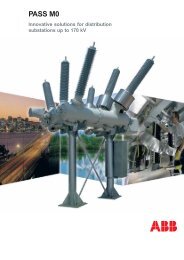
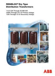
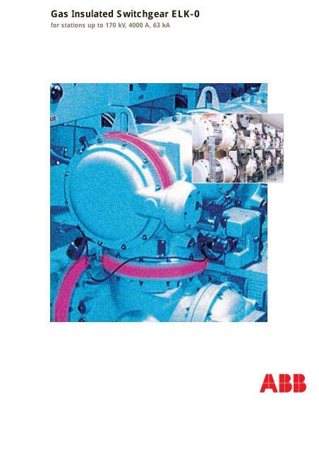
<strong>Gas</strong> <strong>Insulated</strong> <strong>Switchgear</strong> <strong>ELK</strong>-0<br />
for stations up to 170 kV, 4000 A, 63 kA
Content<br />
General ■■■ 3<br />
Set-up<br />
of a substation ■■■ 4-5<br />
The system and its<br />
components ■■■ 6-17<br />
Busbar with combined<br />
disconnector and earthing switch<br />
Circuit breaker with current transformer<br />
Cross unit with combined<br />
disconnector and earthing switch<br />
Make-safe earthing switch<br />
Current and voltage transformer<br />
Cable sealing end<br />
SF 6 outdoor bushing<br />
Supplementary modules<br />
Control cubicle<br />
Transport, Installation ■■■ 18-21<br />
and maintenance<br />
Version examples ■■■ 22-33<br />
Double busbar<br />
Single busbar<br />
H-circuit<br />
1 /2-breaker method<br />
Mesh substation<br />
Technical data ■■■ 34<br />
■ 2
General<br />
Since the presentation of the first<br />
SF 6 -insulated 110-kV-switchbay in<br />
the year 1965, ABB has been among<br />
the pioneers of this technology.<br />
Nowadays the range of high-voltage<br />
applications includes several series of<br />
modular gas-insulated substations<br />
(GIS) for rated voltages of between<br />
52 kV and 800 kV.<br />
Over 2,000 stations with more than<br />
10,000 switch bays demonstrate their<br />
value every day in 70 countries.<br />
Extensive experience in plant operation<br />
in a wide variety of conditions and<br />
with many different requirements<br />
forms the valuable basis of the needsoriented<br />
development and production<br />
of our gas-insulated substations, with<br />
their recognized high quality.<br />
Characteristic advantages of<br />
the <strong>ELK</strong>-0 substations are<br />
– Space saving, compact design<br />
– High availability<br />
– Low maintenance and<br />
repair requirements<br />
– Short delivery and commissioning<br />
period<br />
– Consistent modular<br />
technology
Set-up of a substation<br />
An ingenious modular system<br />
makes possiblea variety of solutions<br />
<strong>Gas</strong>-insulated switchgear (GIS) <strong>ELK</strong>-0<br />
is created by the combination of standardized<br />
function modules such as<br />
circuit breakers, disconnectors and<br />
earthing switches, instrument transformers,<br />
supplementary modules, etc.<br />
These 3-phase modules are connected<br />
together by means of carefully machined<br />
flange connections.<br />
The dimensions of these flanges are<br />
the same with all modules, so that<br />
various components can be combined<br />
very freely. This facilitates the design<br />
of a substation and its planning.<br />
The individual modules are connected<br />
in such a way that subsequent<br />
expansion or the conversion of a substation<br />
can be carried out easily. <strong>Gas</strong>tight<br />
barrier insulators ensure that any<br />
effect on adjacent substation components<br />
is kept to a minimum.<br />
➇<br />
➀<br />
➁<br />
➂<br />
➃<br />
➄<br />
➅<br />
➆<br />
Bay with double busbar and cable<br />
connection<br />
Busbar with combined disconnector<br />
and earthing switch<br />
Circuit breaker<br />
Current transformer<br />
Voltage transformer<br />
Line disconnector with<br />
earthing switch<br />
Make-safe earthing switch<br />
Cable sealing end<br />
Control cubicle<br />
■ 4
The ingenious modular system offers<br />
the planning and project engineer<br />
great flexibility for optimization. He<br />
can thus easily realize his concepts<br />
of the optimum configuration for the<br />
substations. Various criteria such as<br />
basic circuit, routing of lines and<br />
cables, building size, accessibility,<br />
and provisions for extensions and<br />
rapid fault rectification are evaluated<br />
individually and taken into consideration<br />
accordingly.<br />
During the project planning of substations,<br />
all basic circuits used in classic<br />
substation construction can be realized<br />
also with our fully encapsulated GIS.<br />
Substations with single or multiple<br />
busbars – optionally with transfer busbar<br />
also – can be created with standard<br />
modules just as wellwith disconnectable<br />
or switchable busbars and bus couplings.<br />
5 ■
The system and its components<br />
The function of the individual components,<br />
and thus also of the substations,<br />
is dependent on the increasingly strict<br />
system requirements for electrical networks<br />
and their equipment, e.g. economy,<br />
safety, and quality. Here, an<br />
appropriate solution is GIS EXK-0:<br />
compact design, flexible application,<br />
extremely reliable primary and secondary<br />
technology.<br />
Busbar with combined disconnector<br />
and earthing switch<br />
Uniform, standard modules, which are<br />
type-tested and manufactured in large<br />
numbers, are joined to form individual<br />
systems. Structures with great functional<br />
complexity are created by the<br />
combination of clearly defined elements.<br />
This concept is a precondition for<br />
effective, comprehensive quality<br />
assurance.<br />
■ 6<br />
The busbar is made by adjoining busbar<br />
components. The length of these<br />
elements corresponds to the bay<br />
width of 1200 mm.<br />
<strong>Gas</strong>-tight barrier insulators in every<br />
switch bay avoid time consuming gas<br />
filling and emptying of large gas compartments.<br />
Telescopic transverse<br />
assembly elements facilitate tasks<br />
necessary for on-site assembly and<br />
plant extensions or conversions.<br />
The busbar phase conductors are<br />
fastenedbay by bay to gas-tight barrier<br />
insulators. These insulators are each<br />
combined with a telescopic transverse<br />
assembly element,which facilitates the<br />
work necessary in event of station extensions<br />
or conversions. Plug-in contacts<br />
inthe transverse assembly element<br />
connect the busbar conductors. Alternations<br />
in length caused by temperature<br />
fluctuations are thereby<br />
flexibly compensated.<br />
Mechanical strain on the insulators<br />
due to differing heating of the individual<br />
conductors and the enclosures<br />
are thus completely avoided.<br />
A combination of busbar disconnector<br />
and maintenance earthing switch for<br />
subsequent switchgear extension,<br />
maintenance, etc. is an integral part<br />
of each busbar module. The common<br />
operating mechanism for the
combined disconnector and earthing<br />
switch is mounted at the front, and<br />
acts via bevel gears and an insulating<br />
shaft on the three parallel contact pins.<br />
Depending on the direction of movement<br />
the contacts act as disconnector<br />
or earthing switch (maintenance<br />
earthing switch). By means of a crank<br />
handle, manual operation of the combined<br />
disconnector and earthing<br />
switch is also possible.<br />
Two separate position indicators and<br />
auxiliary switches are positively connected<br />
to the operating mechanism.<br />
Furthermore, as the switching does<br />
not take place until immediately before<br />
the contact end positions are reached,<br />
an accurate overview of the contact<br />
position is therefore always assured.<br />
➄<br />
➁<br />
➀<br />
➂<br />
➃<br />
Busbar with combined disconnector<br />
and earthing switch<br />
Contact pin<br />
Disconnector contact<br />
Earthing switch contact<br />
Barrier insulator<br />
Transverse assembly<br />
element<br />
7 ■
Circuit breaker with<br />
current transformer<br />
The circuit breaker is equipped with<br />
two or three connection flanges. Their<br />
position and form is determined by<br />
the station layout. As all other modules<br />
can be connected directly, by<br />
means of appropriate project planning<br />
very compact and thus inexpensive<br />
stations can be formed.<br />
The circuit breaker works as a singlepressure<br />
breaker according to the<br />
auto puffer principle with one break<br />
per pole, and therefore requires very<br />
little maintenance.<br />
The arcing chamber used in this breaker<br />
arises from the outdoor circuit breaker,<br />
which is tested under the most stringent<br />
conditions. It is characterized by<br />
the consistent separation of the continuous-current<br />
contacts and the auxiliary<br />
contacts for the arc extinction.<br />
➃<br />
➁<br />
➂<br />
➀<br />
Circuit breaker with<br />
integrated current transformer<br />
Arcing chamber<br />
Current transformer<br />
Barrier insulator<br />
Hydraulic operating<br />
mechanism<br />
■ 8
Circuit breaker assembly<br />
Long-life auxiliary contacts for arc<br />
extinction and the absence of contact<br />
erosion at the continuous-current<br />
contacts make the need for inspection<br />
and maintenance rare and in<br />
most cases even superfluous.<br />
The puffer piston connected to the<br />
contact nozzle generates the SF 6 gas<br />
flow necessary for arc extinction<br />
during the switch-off movement. The<br />
gas suppresses the operating currents<br />
and small short-circuit currents.<br />
Compression volume and contact<br />
geometry are optimized with regard to<br />
low-overvoltage, soft extinction behavior.<br />
In the heat-up volume, the energy<br />
present in the short-circuit arc is used<br />
to heat the SF 6 gas. The pressure<br />
thus created serves to extinguish<br />
short-circuit currents up to the rated<br />
breaking current.<br />
The compression power to interrupt<br />
the short-circuit currents is thus not<br />
performed by the breaker operating<br />
mechanism. The operating mechanism<br />
– a spring-assisted hydraulic<br />
mechanism is used – can therefore be<br />
made especially simple and reliable.<br />
The majority of the switching operations<br />
are normal-load operations;<br />
most switching operations are thus<br />
performed with the lower mechanical<br />
load from the compression volume.<br />
Reaction forces and wear are accordingly<br />
low.<br />
➀ Breaker closed<br />
➁ Interrupting operating<br />
current<br />
➂ Interrupting<br />
short-circuit current<br />
● Heat-up volume<br />
➀<br />
➁<br />
➂<br />
● Compression volume<br />
Auto puffer principle<br />
9 ■
Hydraulic stored-energy<br />
spring mechanism<br />
The hydraulic stored-energy spring<br />
mechanism of the circuit breaker<br />
forms an ideal connection for the<br />
wear-free power transmission of the<br />
hydraulics system, with the robustness<br />
of a mechanical energy accumulator.<br />
A Belleville spring assembly serves<br />
as an energy accumulator. Its<br />
excellent qualities include reliability,<br />
long-term stability and independence<br />
of temperature.<br />
The drive for three-pole switch actuation<br />
comprises four functional modules:<br />
recharging module with hydraulic<br />
pump and low-pressure tank, accumulator<br />
module with Belleville spring<br />
assembly, working module with drive<br />
piston and integrated end-position<br />
damping and a monitoring and control<br />
module with open-close control<br />
coils. In the version for single-pole<br />
actuation, there are three working and<br />
control modules respectively.<br />
➀<br />
➂<br />
➃<br />
➁<br />
➅<br />
Tripping and enabling of the drive energy<br />
is by means of tried and tested<br />
hydraulic drive technology components.<br />
In accordance with the accepted safety<br />
philosophy, the close-open changeover<br />
valve is equipped with two redundant<br />
open coils.<br />
➄<br />
0 I<br />
Hydraulic stored-energy spring mechanism<br />
Basic diagram<br />
Low pressure oil<br />
High pressure oil<br />
Hydraulic pump<br />
Drive piston<br />
Changeover valve<br />
Storage spring<br />
■ 10
The drive has no pipe or screw<br />
connections. The number of sealed<br />
points to the outside is kept to a minimum.<br />
Pressurized sliding gaskets are<br />
arranged so that unavoidable leaks<br />
can only reach the low-pressure<br />
chamber and never reach the outside.<br />
Hydraulic stored-energy spring mechanism<br />
for three-pole actuation<br />
The high- and low-pressure chambers<br />
are hermetically sealed, excluding the<br />
possibility of long-term change to<br />
the hydraulic fluid caused by oxidization.<br />
Hydraulic stored-energy spring mechanism<br />
for single-pole actuation<br />
11 ■
Cross unit with combined disconnector<br />
and earthing switch<br />
The line disconnector is located in a<br />
cross-shaped module. It is composed<br />
of the same active elements as the<br />
busbar disconnector. Integral component<br />
of the disconnector is a motordriven<br />
earthing switch.<br />
Factory-tested switch bays are<br />
assembled from functional units<br />
In addition, this disconnector provides<br />
the possibility of connecting a voltage<br />
transformer. Here, the electrical<br />
connection is made either before or<br />
after the isolating distance, so that<br />
the voltage is either displayed for the<br />
station side or the line side. The<br />
connecting flange for the voltage<br />
transformer also serves as a test flange<br />
for the high-voltage test of the<br />
substation or the cable.<br />
➃<br />
➂<br />
➀<br />
➁<br />
➆<br />
➇<br />
➄<br />
➅<br />
In general this module is combined<br />
with a voltage transformer, a makesafe<br />
earthing switch, and a cable sealing<br />
end or a pipe outlet line.<br />
■ 12<br />
Line disconnector with<br />
cable sealing end<br />
➀ Contact pin<br />
➁ Disconnector contact<br />
➂ Earthing switch contact<br />
➃ Barrier insulator<br />
➄ Support insulator<br />
➅ Plug-in cable connection<br />
➆ Voltage transformer connection<br />
➇ Make-safe earthing switch
Make-safe<br />
earthing switch<br />
The make-safe earthing switch is fitted<br />
with a spring operating mechanism<br />
which makes contact switching<br />
very fast. It is therefore particularly<br />
suitable as a line earthing switch, as<br />
any conceivable effects in the case of<br />
incorrect switching are thus small.<br />
Make-safe earthing switch<br />
The closed earthing switch can be<br />
isolated from the operational earthed<br />
enclosure during an inspection. There<br />
is therefore the possibility of creating<br />
an electrical connection from outside<br />
via the housing of the earthing switch<br />
and the movable contact pins, which<br />
are insulated from each other, to the<br />
main circuit. This considerably facilitates<br />
the adjustment and checking of<br />
the protective relays, cable checking,<br />
and locating cable faults. During operation,<br />
the insulation is short-circuited.<br />
13 ■
➂ ➁<br />
➀<br />
➄<br />
➃<br />
Current and voltage<br />
transformer<br />
For measurement and protection purposes<br />
inductive, single-phase current<br />
and voltage transformers are used.<br />
For both transformers the primary<br />
insulation consists of SF 6 gas. The<br />
transformers are particularly operationally<br />
safe, as this insulation material is<br />
not subject to any aging.<br />
Feeder current transformers are<br />
arranged in the junction flange of the<br />
circuit breaker. The available core<br />
volume was determined to allow<br />
installation of up to four cores.<br />
Voltage transformer<br />
Primary winding<br />
Secondary winding<br />
Transformer core<br />
Terminal box<br />
Barrier insulator<br />
The voltage transformer has a so-called<br />
SF 6 film insulation. Here, the individual<br />
layers of the winding are insulated<br />
from each other by means of plastic<br />
film and the intermediate spaces<br />
have been impregnated in a special<br />
process with SF 6 gas.<br />
On the secondary side of the voltage<br />
transformers, two measurement windings<br />
and one open delta winding<br />
may be provided for earth fault detection.<br />
The current transformer is designed<br />
as a low-voltage transformer. The<br />
available transformation ratios, secondary<br />
outputs, accuracy classes, etc.<br />
of the transformers correspond to the<br />
usual requirements of modern protection<br />
and measurement technology.<br />
■ 14
Cable sealing end<br />
By means of the cable sealing end,<br />
cables of any kind can be connected.<br />
For the XLPE-insulated cables mostly<br />
in use today, there is a cable sealing<br />
end with a short installation length<br />
and a completely dry solid insulation.<br />
The main elements of the plug-in sealing<br />
ends are the plug-in sockets<br />
made of epoxy resin and the cable<br />
connectors with the pre-manufactured<br />
stress-cones made of silicone<br />
rubber. An advantage is the consistent<br />
separation of the substation and<br />
cable system installations.<br />
For other types of cable, a sealing<br />
end is selected of which the main<br />
component is the longer cable insulator<br />
for liquid-filled sealing ends.<br />
15 ■
SF 6 outdoor bushing<br />
The outdoor bushing allows the transition<br />
from the enclosed substation to<br />
overhead lines or the bare connection<br />
of transformers.<br />
Plastic compound bushings are preferably<br />
used. They are characterized by<br />
a fiber-reinforced support pipe made<br />
of epoxy resin with vulcanized shields<br />
made of silicone rubber. These bushings<br />
are fracture- and explosionproof,<br />
easy to handle and have excellent<br />
pollution layer characteristics on<br />
account of the hydrophobic insulation<br />
material. Upon customer request, traditional<br />
capacitor bushings can also<br />
be provided with porcelain insulation.<br />
Supplementary modules<br />
With regard to station layout various<br />
connection modules may be required<br />
for combination of the equipment.<br />
These are primarily:<br />
– Pipe connections<br />
– Elbow pieces<br />
– T-pieces<br />
The components are equipped with a<br />
support or barrier insulator. Plug-in<br />
and tulip contacts serve for connecting<br />
the conducting paths.<br />
Occasionally, station sections are<br />
combined with a transverse assembly<br />
element in order to facilitate subsequent<br />
station modifications, extensions<br />
or repairs.<br />
■ 16
SF 6 gas system<br />
In accordance with the dual function<br />
of the SF 6 gas as arc extinction and<br />
insulating medium we differentiate<br />
between the extinguishing gas compartments,<br />
and the insulating gas<br />
compartments of the busbars, disconnectors,<br />
instrument transformers,<br />
etc. The gas compartments are<br />
segregated by gas barrier insulators<br />
and the gas pressure is monitored by<br />
temperature compensated pressure<br />
relays (density related relays).<br />
All gas compartments have their own<br />
automatic vacuum coupling, so that<br />
all maintenance jobs, like drawing a<br />
gas sample or topping-up the SF 6<br />
gas can be carried out without difficulty.<br />
Control cubicle<br />
The auxiliary electrical units required<br />
for command input, warning, locking,<br />
etc. are accommodated in their own<br />
individual control cubicles.<br />
The units are connected to the control<br />
cubicles by means of control<br />
cables with coded multiple connectors.<br />
These connections are already<br />
manufactured and tested in the factory.<br />
The electrical connections between<br />
control cubicle and control<br />
room are routed on terminal strips.<br />
The door is fitted with the mimic diagram<br />
with the position indicators,<br />
associated control switches and<br />
visual alarm indicators. By means of<br />
key-switches, the units' locks are<br />
released or switched to local or remote<br />
control.<br />
As an alternative to the conventional<br />
electromechanical control system, a<br />
microprocessor-controlled bay control<br />
and protection device REF542plus<br />
can be used. It combines the basic<br />
functions control, protection, communication<br />
and monitoring. Standardized<br />
digital interfaces permit easy connection<br />
to the substation control system.<br />
17 ■
Transportation, assembly,<br />
and maintenance<br />
Factory-assembled and<br />
-tested substations<br />
Thanks to the low weight of the <strong>ELK</strong>-0<br />
components, transportation and<br />
assembly of a substation is easy.<br />
Preferably, <strong>ELK</strong>-0 substations are<br />
supplied in completely assembled and<br />
tested bays with the relevant control<br />
cubicles.<br />
Factory-tested switchyard bays<br />
Here, the following advantages may<br />
be applicable:<br />
– The assembly period at the installation<br />
site is very short and the work<br />
for substation commissioning is<br />
uncomplicated.<br />
– The insulating capacity has been<br />
proven in the factory by means of<br />
routine tests of the complete bays.<br />
As here a partial-discharge measurement<br />
was also carried out, impairment<br />
of the insulating capacity due<br />
to material or manufacturing faults<br />
can be safely ruled out.<br />
– On account of the small bay<br />
dimensions and weights, <strong>ELK</strong>-0<br />
substations can also be delivered<br />
by air freight without problem.<br />
Complicated packaging and preservation<br />
are not required, so commercial<br />
use of the station can start<br />
earlier.<br />
After the station has been set up, the<br />
gas compartments are filled with SF 6<br />
gas. For this purpose, special service<br />
trolleys are available. As all gas compartments<br />
are provided with valve<br />
couplings which can be opened without<br />
gas or pressure loss, these operations<br />
are very simple to perform. <strong>Gas</strong><br />
losses and emissions are therefore<br />
almost completely eliminated. After<br />
the switchgear has been checked for<br />
perfect mechanical operations, the<br />
results of the commissioning tests are<br />
recorded.<br />
■ 18
On-site assembly of complete bays<br />
High voltage test<br />
19 ■
Maintenance<br />
The operational safety of fully encapsulated<br />
SF 6 insulated substations is<br />
subject to no external influence resulting<br />
from dirt, moisture or similar. The<br />
GIS <strong>ELK</strong>-0 therefore requires extremely<br />
low-maintenance.<br />
In the case of inspections, the inside<br />
of the switchgear is not interfered<br />
with, so the substation can remain in<br />
operation. The condition of the gas<br />
and hydraulic oil is checked and the<br />
actuators, auxiliary contact units,<br />
density monitors are subjected to a<br />
function test.<br />
Circuit-breakers and disconnectors<br />
should be inspected only after 5,000<br />
mechanical operating cycles. In addition,<br />
repair of the circuit-breaker is<br />
scheduled after approx. 10-20 shortcircuit<br />
cut-outs at the earliest, depending<br />
on the switched-off short-circuit<br />
current.<br />
Experience shows that these limit<br />
values are far in excess of the requirements<br />
of practical operation.<br />
With respect to network planning, the<br />
usual precautionary measures and<br />
redundancies can therefore be considerably<br />
reduced.<br />
■ 20
21 ■
Version examples<br />
<strong>Gas</strong> insulated <strong>ELK</strong>-0 substations are<br />
always the right choices when the low<br />
space requirements are an important<br />
criterion for the choice: for supplying<br />
power to cities and conurbations,<br />
industrial complexes, and when<br />
aggressive environmental conditions<br />
necessitate a sheltered location.<br />
The following examples prove the flexibility<br />
of the system and are intended<br />
to provide stimulus for the conception<br />
and planning of new substations.<br />
All the usual station circuits can be<br />
optimally implemented on account of<br />
the modular component system. At<br />
the same time, it is possible to take<br />
into consideration the various requirements<br />
regarding building dimensions,<br />
subsequent station extensions, security<br />
of supply, comprehensive station<br />
overview, access to equipment, protection<br />
concept, etc. on the basis of a<br />
solution tailored to the individual case<br />
in accordance with its value.<br />
The bay width is basically 1.2 m. The<br />
required building depth is generally<br />
7 m, the building height less than 5 m.<br />
No crane is necessary for assembling<br />
the factory-assembled and -tested<br />
switch bays and maintenance of the<br />
equipment; however, installation of a<br />
crane is recommended to facilitate the<br />
work and to save time.<br />
■ 22
23 ■
Double busbar<br />
This circuit is the most common circuit<br />
version for important key-point<br />
substations, power plant supply, etc.<br />
If both busbars are operated with<br />
equal priority – instead of the operating<br />
method with main and reserve<br />
busbars – the principle of busbar<br />
separation can be applied to reduce<br />
the short-circuit current. The two busbars<br />
and their feeders belong to<br />
separate sub-networks. If required,<br />
individual feeders can be allocated to<br />
the other sub-network.<br />
This concept relieves the stations as a<br />
result of low short-circuit loading, longer<br />
maintenance intervals and offers<br />
greater supply security.<br />
The possible coupling versions are<br />
particularly varied: The simple bus<br />
coupling or the combined bus sectionalization<br />
and coupling with six or<br />
eight disconnectors are two examples.<br />
Double disconnectors even<br />
allow subsequent high-voltage tests<br />
after station extensions or maintenance<br />
measures during partially normal<br />
operation.<br />
E07 E06 E05 E04 E03 E02 E01<br />
■ 24
Feeder E01, E03, E05-E07<br />
1200<br />
500<br />
2350<br />
7000<br />
3600<br />
2500<br />
E07 E06 E05 E04 E03 E02 E01<br />
4900<br />
7000<br />
APPR.10000<br />
14000<br />
Feeder E02<br />
25 ■
Single busbar<br />
Smaller stations or single- or doublefeed<br />
stations are frequently designed<br />
with single busbars. Here, in the interest<br />
of adaptable system management,<br />
bus section couplings and bus<br />
couplings are provided. This means,<br />
for example, that part of the station<br />
can remain in operation during station<br />
extension work.<br />
The layout of a station with simple<br />
busbar is similar to that of double<br />
busbar stations, as only the lower or<br />
upper busbar is eliminated. If the<br />
appropriate connection flanges are<br />
already provided on the circuit-breakers<br />
on the initial version, it is easy<br />
subsequently to upgrade to a double<br />
busbar.<br />
1200<br />
Feeder E01-E03<br />
2950<br />
3600<br />
2500<br />
7000<br />
FUTURE E01 E02 E03 E04 E05 E06 E07 FUTURE<br />
7000<br />
4500<br />
500<br />
16000<br />
■ 26
VIEW X<br />
FUTURE E01 E02 E03 E04 E05 E06 E07 FUTURE<br />
E01 E02 E03 E04 E05 E06 E07<br />
27 ■
H-circuit<br />
The H-circuit is frequently used to<br />
supply industrial companies or smaller<br />
regions. Two feed lines and two stepdown<br />
transformers are optimal with<br />
regard to supply reliability and network<br />
reserves. The station can be operated<br />
as a double-feed station, with closed<br />
cross connection also as a ring substation.<br />
If subsequent possibilities for extension<br />
are not required, the especially<br />
compact version without busbar is<br />
selected.<br />
If a subsequent station extension is<br />
under consideration, the simple busbar<br />
with section coupling is selected<br />
as basic layout. There is even subsequently<br />
the possibility of converting<br />
this to a station with double busbar<br />
and bus coupling.<br />
Section A-A<br />
E01<br />
E03<br />
17500<br />
E01<br />
(E03)<br />
E02<br />
(E04)<br />
E02<br />
E04<br />
20000<br />
■ 28
E01<br />
E03<br />
E02<br />
E04<br />
29 ■
1 1 /2 - breaker method<br />
The 1 1 /2 -breaker method is a traditional<br />
circuit with which the non-availability<br />
of the circuit-breaker during maintenance<br />
is taken into particular consideration.<br />
It is used primarily with<br />
maintenance-intensive breakers, and<br />
where the secondary medium-voltage<br />
network does not take even a brief<br />
additional load, and a primary transmission<br />
network is not provided.<br />
Such networks or stations are usually<br />
operated in such a way that all switches<br />
are closed. Each feeder is then<br />
fed from two sides, so that even a<br />
faulty busbar can be switched off<br />
without reducing the supply.<br />
EXCEPT E02<br />
EXCEPT E11<br />
EXCEPT E14<br />
2500<br />
■ 30
F01 F02 F03 F04 F05 F06 F07 F08 F09 F10 F11 F12 F13 F14 F15<br />
3600<br />
9500<br />
E01 E02 E03 E04 E05 E06 E07 E08 E09 E10 E11 E12 E13 E14 E15<br />
EXCEPT E05<br />
9500<br />
6050<br />
500<br />
31 ■
Mesh substation<br />
Similarly to the 1 1 /2-breaker method,<br />
the ring bus allows uninterrupted operation<br />
of all cable and line feeders<br />
even in the event of switchgear maintenance<br />
work. With this circuit, the<br />
number of breakers and the cable<br />
and line feeders is equal, so the station<br />
is in general more inexpensive<br />
than a corresponding version with 1 1 /2<br />
breakers per bay.<br />
EDER E01<br />
2500<br />
3500<br />
7500<br />
■ 32
E01 E02 E03 E04<br />
Preferentially small substations with<br />
for instance four bays are built-up<br />
with this layout. Switching of one feeder<br />
implies at least short-time interrupting<br />
the ring-busbar. This is inappropriate<br />
for big substations, because<br />
in the case of a short-circuit failure<br />
the unplanned opening of the ring<br />
busbar causes considerable load-flow<br />
variations or supply interruptions.<br />
VIEW X<br />
FEDER E02<br />
7500<br />
E01 E02 E03 E04<br />
9500<br />
33 ■
Technical data<br />
Rated values*<br />
Operating voltage kV 72.5 123 (126) 145 170<br />
Operating frequency Hz 50 / 60<br />
Lightning impulse withstand voltage to ground kV 325 550 650 750<br />
Lightning impulse w. voltage over isolating distance kV 375 630 750 860<br />
Power frequency withstand voltage to ground kV 140 230 275 325<br />
Power frequency w. voltage over isolating distance kV 160 265 315 375<br />
Operating current A 1250 – 4000<br />
Peak withstand current kA 80 –164<br />
Short time withstand current kA 31.5 – 63<br />
Breaking current kA 31.5 – 63<br />
Making current kA 80 –164<br />
Min. insulating gas pressure at 20 °C kPa 520<br />
Min. quenching gas pressure at 20 °C kPa 600<br />
*Higher data on request<br />
■ 34
35 ■