PASS M0 - Innovative solutions for distribution substations up to
PASS M0 - Innovative solutions for distribution substations up to
PASS M0 - Innovative solutions for distribution substations up to

You also want an ePaper? Increase the reach of your titles
YUMPU automatically turns print PDFs into web optimized ePapers that Google loves.
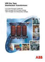
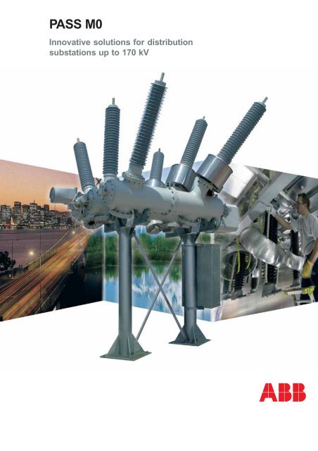
<strong>PASS</strong> <strong>M0</strong><strong>Innovative</strong> <strong>solutions</strong> <strong>for</strong> <strong>distribution</strong><strong>substations</strong> <strong>up</strong> <strong>to</strong> 170 kV
The conceptIn the <strong>to</strong>day’s changing market, thesubstation is becoming more and more akey element <strong>to</strong> meet end users requirementssuccessfully and economically. Many existing<strong>substations</strong> have outlived their operational lifeand a one-<strong>to</strong>-one replacement of conventional AIScomponents like circuit-breakers anddisconnec<strong>to</strong>rs is not economically advisable;completely new <strong>substations</strong> have <strong>to</strong> meet <strong>to</strong>ughrequirements in terms of occ<strong>up</strong>ied space,environment and availability. Substationsextensions require high flexibility on primaryequipment, <strong>to</strong> cope with already existing controlsystems, lack of available space, limited downtime.<strong>PASS</strong> <strong>M0</strong> is the ideal primary equipment <strong>to</strong> meetall the above scenarios and it is the result of adifferent thinking; think <strong>for</strong> the per<strong>for</strong>mance of thesubstation as a complete system.<strong>PASS</strong> <strong>M0</strong> switchgear limits the number ofequipment <strong>to</strong> what is really necessary <strong>to</strong> assurethe best functionality of the bay; its modular designassures all the possible substation layouts can berealized.BusBarFig. 1<strong>PASS</strong> <strong>M0</strong> in its standard configuration (Single BusBar):1: Combined disconnec<strong>to</strong>r/earthing switch2: Circuit-breaker3: Current trans<strong>for</strong>mer.LineThe flexibility<strong>PASS</strong> (Plug And Switch System) is based on ABBextensive experience in manufacturing bothairinsulated switchgear (AIS) and gas-insulatedswitchgear (GIS).<strong>PASS</strong> can also be thought as “Per<strong>for</strong>mance AndSave Space”: any substation layout can be metwhile making efficient use of available space.Per<strong>for</strong>mance is guaranteed by the wealth ofexperience in research and development,manufacture and operation of switchgear whichconstitute the basis of ABB know-how.The key characteristic of <strong>PASS</strong> is its compact andmodular design which encompasses severalfunctionsin one module, as <strong>for</strong> example:● Bushings <strong>for</strong> connection <strong>to</strong> one or two BusBarsystems● One circuit-breaker● One or more combined disconnec<strong>to</strong>r/earthingswitches● One current trans<strong>for</strong>mer2 - <strong>PASS</strong> <strong>M0</strong>
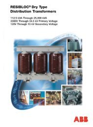
Fig. 2The diagram shows <strong>PASS</strong> <strong>M0</strong> inDouble BusBar configuration.1: Combined disconnec<strong>to</strong>r/earthingswitch on BusBar 1 and BusBar 2.2: Circuit-breaker.3: Current trans<strong>for</strong>mer.LineBusBar 2<strong>PASS</strong> is equivalent <strong>to</strong> a high voltage bay.In <strong>PASS</strong> <strong>M0</strong> all live parts, excluding BusBars, areencapsulated in a grounded aluminium tankwhich is filled with pressurised SF6 gas. Each polehas its own enclosure, <strong>to</strong> increase availability andsafety. The enclosures are of casted and weldedaluminium construction.Using standardised components, the addition of asecondary BusBar system <strong>to</strong> <strong>PASS</strong> <strong>M0</strong> isstraight<strong>for</strong>ward.As the picture Fig. 3 shows, with such aconfiguration <strong>PASS</strong> <strong>M0</strong> is a complete High Voltagesubstation in incoming/outgoing configuration:● the first bushings are connected <strong>to</strong> the powertrans<strong>for</strong>mer;● the second bushings are connected <strong>to</strong> theoutgoing line;● the third bushings are connected <strong>to</strong> theincoming line.There<strong>for</strong>e there is no traditional BusBar, i.e. theBusBar is realized within the <strong>PASS</strong> <strong>M0</strong> by meansof the first and second bushings.<strong>PASS</strong> <strong>M0</strong> in this configuration is a reallybreakthrough as system concept (patented) <strong>for</strong><strong>distribution</strong> substation.Fig. 3 - <strong>PASS</strong> <strong>M0</strong> Double BusBar.<strong>PASS</strong> <strong>M0</strong> - 3
General descriptionCircuit -breakerThe <strong>PASS</strong> <strong>M0</strong> circuit-breaker is a single pressureinterr<strong>up</strong>ter operating on the well-established selfblastprinciple.The energy <strong>for</strong> interr<strong>up</strong>ting currents is partlys<strong>up</strong>plied by the arc itself, thereby reducing theenergy requested from the operating mechanismof about 50% compared with a conventionalpuffer-type circuit-breaker.Combined Disconnec<strong>to</strong>r/Earthing Switch<strong>PASS</strong> <strong>M0</strong> is equipped with a three pole operatedcombined disconnec<strong>to</strong>r/earthing switch. Theoperating principle (patented) is based <strong>up</strong>on therotary motion of the contact which can be closedon the BusBar, earthed or left in the neutralposition.The mechanism is composed of minimal numberof mechanical components and it is intrinsicallyreliable, and maintenance free. This modulardesign can be applied <strong>to</strong> <strong>PASS</strong> <strong>M0</strong> in SingleBusBar configuration, Double BusBarconfiguration and on all the bushings: BusBar orline sides.All the combinations are possible.In both cases, Single BusBar and Double BusBar,the position of the combined disconnec<strong>to</strong>r/earthing switch is clearly indicated at all times byan indica<strong>to</strong>r which is mechanically co<strong>up</strong>led <strong>to</strong> theshaft. In addition <strong>to</strong> this, a visual confirmation ispossible by means of a view port in the enclosure.The disconnec<strong>to</strong>r/earthing switch may, in anemergency, be operated manually by means of acrank.Current Trans<strong>for</strong>mer<strong>PASS</strong> <strong>M0</strong> is equipped with a conventional currenttrans<strong>for</strong>mer, <strong>to</strong> meet cus<strong>to</strong>mer requirements, e.g.<strong>for</strong> retrofitting. Several combinations of cores <strong>for</strong>protection and measurements with differentburdens are available. Up <strong>to</strong> 5 cores can be fittedin<strong>to</strong> the current trans<strong>for</strong>mer.BushingsOverhead lines and BusBars are connected <strong>to</strong> the<strong>PASS</strong> <strong>M0</strong> by air bushings. The main insulation iscompressed SF6-gas. The insula<strong>to</strong>r consists of anepoxy impregnated fibreglass tube with siliconrubber sheds. The flanges are heatshrunk andglued on<strong>to</strong> the tube making an extremely strongand gastight joint. The silicon rubber sheds arecast on<strong>to</strong> the tube and chemically bonded <strong>to</strong> it,thus allowing no moisture or contamination <strong>to</strong>enter between them. The silicon rubber sheds arehydrophobic and give very good rain and pollutionper<strong>for</strong>mance. The main features are:Fig. 4The operating mechanism is of the spring type. This typeof drive s<strong>to</strong>res energy in a spring which is dischargedduring operations.• high safety (crack and explosion resistant)• low weight• excellent pollution and rain per<strong>for</strong>mance• sands<strong>to</strong>rm resistant• maintenance free.SF6 Gas SystemThe compact design of the <strong>PASS</strong> <strong>M0</strong> module isdue <strong>to</strong> the excellent insulation qualities of SF6gas. Its dielectric strength in a homogeneous fieldis about 2.5 times greater than that of air at thesame temperature and pressure. The design of thelive components is such that the field <strong>distribution</strong>is as homogeneous as possible, which allows theintrinsic strength of the insulating gas <strong>to</strong> be utilizedmost efficiently.❑ SF6 gas pressures of the <strong>PASS</strong> <strong>M0</strong>module at 20 °C• Filling pressure ........................ 680 kPa (abs)• First alarm level ........................ 620 kPa (abs)• Nominal insulation pressure(blocking pressure) ................ 600 kPa (abs)Filling pressure is about 15% higher than thenominal insulation pressure. This guaranteessufficient gas density over a long operationalperiod. To ensure minimum gas loss duringoperation all enclosures, connections and valvesare subjected <strong>to</strong> severe gas-tightness tests in thefac<strong>to</strong>ry.❑ Gas density controlEach <strong>PASS</strong> <strong>M0</strong> pole builds a single gas compartment.Since the dielectric strength of the switchgear andthe breaking capacity of the SF6 circuit-breakerdepend on the density of the SF6 gas, a gas densityrelay is installed <strong>to</strong> control gas density and detectleakage.4 - <strong>PASS</strong> <strong>M0</strong>
Fig. 5Combined disconnec<strong>to</strong>r/earthing switch <strong>for</strong> <strong>PASS</strong> <strong>M0</strong> Single BusBar.The contact is closed on the BusBar.Fig. 6The combined disconnec<strong>to</strong>r/earthing switch <strong>for</strong> the Double BusBarconfiguration is achieved using a combination of two disconnec<strong>to</strong>r/earthing <strong>for</strong> the Single BusBar.In the picture the right contact is closed whereas the left one is open.❑ Over-pressure reliefTo protect against excessive over-pressure due<strong>to</strong> unlikely internal arc faults a metal r<strong>up</strong>turediaphragm(r<strong>up</strong>ture disk) is installed. When a predeterminedoverpressure is reached, the r<strong>up</strong>turedisk will break open and relieve the pressurewhich would otherwise cause the enclosure itself<strong>to</strong> r<strong>up</strong>ture. Deflec<strong>to</strong>rs in front of the diaphragmsensure the safety of personnel.S<strong>up</strong>port structureThe s<strong>up</strong>port structure <strong>for</strong> the <strong>PASS</strong> <strong>M0</strong> moduleis hot-dip galvanised and painted <strong>for</strong> protectionagainst corrosion. It is designed in such a way<strong>to</strong> offer the maximum s<strong>up</strong>port and robustnesswhile keeping civil works at minimum.Integration with secondary system<strong>PASS</strong> <strong>M0</strong> is equipped with a conventionalprocess co<strong>up</strong>ling: e.g. auxiliary contacts <strong>for</strong>circuit-breaker and disconnec<strong>to</strong>r/earthing switchpositions and relay outputs <strong>for</strong> signalling (e.g.SF6 lock out).This conventional interface allows the <strong>PASS</strong> <strong>M0</strong><strong>to</strong> be connected with any control and protectionsystem, thus enabling retrofitting and <strong>up</strong>gradingof already existing <strong>substations</strong>.Once installed in the field, two multipolar cablesfrom the local control cubicle are the only items<strong>to</strong> connect <strong>PASS</strong> <strong>M0</strong> <strong>to</strong> the control and protectionsystem.Environmental impact and Life Cycle Cost<strong>PASS</strong> <strong>M0</strong> is kind <strong>to</strong> the environment. Global lifecycle cost and impact on the environment wereconsidered during <strong>PASS</strong> <strong>M0</strong> design sincebeginning. Compared <strong>to</strong> a conventional airinsulated solution which implements the samefunctions, <strong>PASS</strong> <strong>M0</strong> meets the following targets:• SF6 reduced by 80%• maintenance cost reduced by 38%• space reduced by 70%• <strong>to</strong>tal life cycle cost less than 60%Compared <strong>to</strong> a conventional 5 bays H layout airinsulated substation, the global life cycle cost<strong>for</strong> <strong>PASS</strong> <strong>M0</strong> is estimated <strong>to</strong> be more than 30%lower (see diagram on page 28).Moreover <strong>PASS</strong> <strong>M0</strong> has been subject <strong>to</strong> the LCA(Life Cycle Assessment), a study that coversall environmental aspects during the whole lifeof the product.In this regard, EDP (EnvironmentalProduct Declaration) provides a quantitativeand verified description of the environmentalper<strong>for</strong>mance of <strong>PASS</strong> <strong>M0</strong>, viewed from a comprehensivelife circle perspective.TransportationNo special arrangements are needed <strong>for</strong> shippingand transportation. <strong>PASS</strong> <strong>M0</strong> fits in<strong>to</strong> a standardtruck container and does not require anypackaging. Once on site a simple 30° rotation ofthe outer poles is needed <strong>for</strong> the final layout of<strong>PASS</strong> <strong>M0</strong>.The following pictures show <strong>PASS</strong> <strong>M0</strong> 145 kVin Single and Double BusBar configuration intransportation and operation positions.The compactness in both positions is selfevident.<strong>PASS</strong> <strong>M0</strong> - 5
Fig. 7A<strong>PASS</strong> <strong>M0</strong> 145 kV SBBTransportation Position.Fig. 7B<strong>PASS</strong> <strong>M0</strong> 145 kV SBBOperation Position.Fig. 7C<strong>PASS</strong> <strong>M0</strong> 145 kV DBBTransportation Position.Fig. 7D<strong>PASS</strong> <strong>M0</strong> 145 kV DBBOperation Position.6 - <strong>PASS</strong> <strong>M0</strong>
Manufacturing and Quality AssuranceManufacturing<strong>PASS</strong> <strong>M0</strong> is born from the wealth ofexperience in research and development,manufacturing and operation of switchgearswithin ABB Power Technologies in Lodi. Partswhich are not directly manufactured ares<strong>up</strong>plied by other ABB companies. The choiceof materials, s<strong>up</strong>pliers, sub-assemblies andworking procedures is governed by the internalstandard quality assurance programs, whichmeet the requirements laid down by ISO 9001and 14001.On-site assemblyA <strong>PASS</strong> <strong>M0</strong> module is equivalent or almostequivalent <strong>to</strong> a complete bay. It allows theinstallation of <strong>substations</strong> in a short period of time:each bay can be unloaded from the trailer anddirectly installed on the plat<strong>for</strong>m foundation(extremely small).The on-site erection of <strong>PASS</strong> <strong>M0</strong> modules issimplified since <strong>PASS</strong> <strong>M0</strong> is assembled in thefac<strong>to</strong>ry be<strong>for</strong>e the shipment.The installation of a <strong>PASS</strong> <strong>M0</strong> requires about afew hours with a crew of two (not including gashandling).Standards<strong>PASS</strong> <strong>M0</strong> meets the requirements set out in thefollowing documents:• IEC (all relevant standards - see technicaldata)• ISO 9001 and 14001.The enclosure complies with the followingstandard <strong>for</strong> pressure vessels:• CENELEC EN 50052.Quality handbooks and inspection plans can beprovided <strong>to</strong> the cus<strong>to</strong>mer on request.Quality assurance testingType testsAll type tests specified by the relevant IECstandards have been passed. Tests can berepeated on request at cus<strong>to</strong>mer’s expense.Copies of certificates and reports can be providedon request.Routine testsBe<strong>for</strong>e leaving the fac<strong>to</strong>ry all <strong>PASS</strong> <strong>M0</strong> units aresubject <strong>to</strong> the following routine tests:• AC High voltage test;• dielectric tests on auxiliary control units;• pressure tests of the enclosure according <strong>to</strong>CENELEC-EN 50052 1986 TC 17C WG MPE.The enclosure is tested at double the designoverpressure <strong>for</strong> one minute. This test alsomeets the requirements of IEC 60517;• gas tightness;• mechanical functional test of all moving parts;• test of all equipment and accessories;• AC high voltage test with PD measurement.These tests ensure perfect functionality of allcomponents be<strong>for</strong>e they leave the fac<strong>to</strong>ry. Atest report is produced <strong>for</strong> all tests. If sorequired cus<strong>to</strong>mers can attend routine testinghaving received invitations well in advance.On-site testingAfter final assembly or commissioning of thesubstation, the following tests are made:• mechanical functional testing of circuitbreaker,and combined disconnec<strong>to</strong>r/earthingswitch;• testing of SF6 gas-tightness;• random sampling of moisture content inindividual components;• checking and functional testing of control andauxiliary equipment.After completion of these tests a handover reportis completed.Fig. 8A UNI EN ISO 9001Italian Certification ofCompanies QualitySystemsB UNI EN ISO 14001Certification ofCompaniesEnvironmentalManagement Systems<strong>PASS</strong> <strong>M0</strong> - 7
<strong>PASS</strong> <strong>M0</strong> technical dataGeneral RatingsRated frequency ..................................................................................................................................... 50/60 HzRated voltage .......................................................................................... 170 kV ............... 72,5/123/145/170 kVRated current ....................................................................................................................................... .2500 A (1)Max. test voltage:a) Phase <strong>to</strong> ground:Rated short time power frequency withstand voltage, 1 min ......... 325 kV ................ 140/230/275/275 kVRated lightning impulse withstand voltage 1,2/50 µs ...................... 750 kV ................ 325/550/650/650 kVb) Across isolating distance (circuit-breaker, disconnec<strong>to</strong>r):Rated short time power frequency withstand voltage, 1 min ......... 375 kV ................ 160/265/315/315 kV.Rated lightning impulse withstand voltage 1,2/50 µs ...................... 860 kV ................ 375/630/750/750 kVRated short time withstand current (3 s) ..................................................................................................... 40 kARated peak withstand current .................................................................................................................... 100 kAAmbient temperatureMin. (2) ............................................................................................... -25 °C ...................................... - 30 °CMax. ..................................................................................................................................................... + 55 °CGas loss per year ......................................................................................................................................... < 1%WeightSingle BusBar ..................................................................................................................................... 1900 kgDouble BusBar ................................................................................................................................... 2150 kgIncoming - outgoing ............................................................................................................................ 2300 kgSF6 pressures (20 °C) (absolute values)Filling pressure ............................................................................... 700 kPa .................................... 680 kPaFirst alarm level .............................................................................. 660 kPa .................................... 620 kPaNominal insulating pressure (blocking pressure) ......................... 640 kPa ................................... .600 kPa(1) Up <strong>to</strong> 3150 A, on request.(2) Lower temperatures can be reachedby a gas mixture on request.Circuit-breakerSingle interr<strong>up</strong>ter, type LTB-DRated short circuit breaking current ..................................... 40kA / 50 HzRated short circuit breaking current ..................................... 40kA / 60 HzRated short circuit making current (close and latch) ............... 100 kA pK.Line charging switching ............................................................................... 63ACable charging switching .......................................................................... 160ADrive ........................................................ 3 poles spring operated / Single poleType ....................................................................................... BLK 222 / BLK 82Rated operating sequence ............................................. O-0.3 s-CO-1min-COOpening time ......................................................................................... =
Disconnec<strong>to</strong>r/Earthing SwitchDrive .............................................................................. 3 poles mo<strong>to</strong>r operatedRated s<strong>up</strong>ply voltage of auxiliary circuits ............................................ 110VDCSwitching time from line <strong>to</strong> earth ................................................................ 5.5 sEmergency manual operation possible (hand-crank).Contact position visible through porthole.Current Trans<strong>for</strong>merType ........................................................................................................ ring CTMeasurement class ...........................................................................0.2/0.5/1.0Protection class ............................................................ meets all requirementsIP code (IEC 60144) .................................................................................. IP 54• Current Trans<strong>for</strong>mer (example)• Current ratio ................................................................... .300-600/1-1-1 A• Cores ....................................................................................................... 3• Accuracy class ........................................................ 10 VA, cl. 0.2, FS
Substation layouts with <strong>PASS</strong> <strong>M0</strong> innovative solution<strong>PASS</strong> <strong>M0</strong> IOSFig. 9The cooperation with Enel in Italy originated acompletely new system concept - patented - <strong>for</strong><strong>distribution</strong> <strong>substations</strong>. The principle is <strong>to</strong> usecomponents <strong>for</strong> double BusBar system <strong>for</strong> aSingle BusBar substation configuration.<strong>PASS</strong> <strong>M0</strong> <strong>for</strong> Double BusBar fits very well in thisconcept and it is used as a complete HVsubstation.No traditional BusBar are used, i.e. the BusBar isinside the <strong>PASS</strong> <strong>M0</strong> (see single line diagram fig. 9).Cus<strong>to</strong>mer requirements in terms of current andvoltage detection and measurements are fulfilledby non conventional sensors on board of <strong>PASS</strong><strong>M0</strong>. Conventional current trans<strong>for</strong>mer is alsoavailable.<strong>PASS</strong> <strong>M0</strong> used in this configuration presents a lo<strong>to</strong>f advantages <strong>for</strong> cus<strong>to</strong>mer:• reduction of occ<strong>up</strong>ied space;• reduced environmental impact (more andmore a critical fac<strong>to</strong>r in highly populated andhighly industrialized countries);• reduction of losses due <strong>to</strong> smaller MVnetworks (HV can be brought closer <strong>to</strong> theend user and the number of HV <strong>substations</strong>can be substantially increased);2Fig. 101. Single line diagram (<strong>PASS</strong> <strong>M0</strong> IOS substation, ENEL).2. <strong>PASS</strong> <strong>M0</strong> Double BusBar Fed-through.10 - <strong>PASS</strong> <strong>M0</strong>
Fig. 11A<strong>PASS</strong> <strong>M0</strong> IOS 145-170 kVTransportation Position.Fig. 11B<strong>PASS</strong> <strong>M0</strong> IOS 145-170 kVOperation Position.• reduction of short circuit current (benefits <strong>for</strong>all the equipment);• easy installation;• reduced commissioning time of the wholesubstation;• substation is completely transportable (threepieces: HV switchboard <strong>PASS</strong> <strong>M0</strong>, powertrans<strong>for</strong>mer, MV feeders);• reduced life cycle cost.Fig. 12Fed-through S/S The <strong>to</strong>tal substation area including highvoltage equipment, trans<strong>for</strong>mer, medium voltageequipment and control cubicles is ~40m x 18m only.<strong>PASS</strong> <strong>M0</strong> - 11
Some applicationsH scheme single BusBar substationThe drawing below shows a H scheme Single BusBar indoor substation, composed by 2 incomingfeeder bays and 2 trafo bays. It also presents a co<strong>up</strong>ling bay.There is a <strong>PASS</strong> <strong>M0</strong> <strong>for</strong> each bay (<strong>to</strong>tal 4). The switchyard area is 16mx22m.Fig. 13H scheme Single BusBarindoor substation.Single BusBar with co<strong>up</strong>ling bayThe drawing below shows a substation Single BusBar with 6 feeder bays, 2 trafo bays and 2 spare bays<strong>for</strong> future expansions. A bus co<strong>up</strong>ler bay is present. There is a <strong>PASS</strong> <strong>M0</strong> <strong>for</strong> each bay (<strong>to</strong>tal 11).The switchyard area is 14mx54m.Notice that <strong>PASS</strong> <strong>M0</strong> can be moved in order <strong>to</strong> fulfill the BusBar phase distance.Fig. 14Single BusBar withco<strong>up</strong>ling bay, <strong>to</strong>p view.12 - <strong>PASS</strong> <strong>M0</strong>
Fig. 15Trans<strong>for</strong>mer and line bays.Fig. 16Co<strong>up</strong>ling bay, section view.<strong>PASS</strong> <strong>M0</strong> - 13
<strong>PASS</strong> <strong>M0</strong> variantFig. 17 B - <strong>PASS</strong> <strong>M0</strong> IOS.Fig. 17 A - <strong>PASS</strong> <strong>M0</strong> SBB with GIS VT’s.Fig. 17 D - <strong>PASS</strong> <strong>M0</strong> DCB.14 - <strong>PASS</strong> <strong>M0</strong>Fig. 17 C - <strong>PASS</strong> <strong>M0</strong> DBB.
Fig. 19Fig. 18<strong>PASS</strong> <strong>M0</strong> SBB cable ends.Fig. 20<strong>PASS</strong> <strong>M0</strong> SBB with additional Current Trans<strong>for</strong>mer.<strong>PASS</strong> <strong>M0</strong> DCB cable ends and bushing.<strong>PASS</strong> <strong>M0</strong> - 15
<strong>PASS</strong> <strong>M0</strong> 115/34.5 - 30 MVAFig. 21Mobile Substation intransport condition.<strong>PASS</strong> <strong>M0</strong> 115/34.5 - 30 MVAFig. 22Mobile Substation inoperating condition.16 - <strong>PASS</strong> <strong>M0</strong>
<strong>PASS</strong> <strong>M0</strong> 132/20 - 25 MVAFig. 23Mobile Substation intransport condition.<strong>PASS</strong> <strong>M0</strong> 132/20 - 25 MVAFig. 24Mobile Substation inoperating condition.<strong>PASS</strong> <strong>M0</strong> - 17
<strong>PASS</strong> <strong>M0</strong> Railway Mobile SubstationFig. 25Mobile Substation <strong>for</strong>Italian railway in transportcondition.Fig. 26Mobile Substation <strong>for</strong>Italian railway in operatingcondition.18 - <strong>PASS</strong> <strong>M0</strong>
LCC - Life Cycle Cost (examples from OSCAR)Fig. 27 A-BCus<strong>to</strong>mer needs:– feed energy <strong>to</strong> S/S A, B, C– minimum space– maximum availability on S/S B– cost.ABCus<strong>to</strong>mer solution:– conventional Double BusBar system.Fig. 27 C-DC<strong>PASS</strong> <strong>M0</strong> solution:– <strong>PASS</strong> <strong>M0</strong>, Single busbar– same functionalities– reduced space occ<strong>up</strong>ation– reduced cost.DLife Cycle Cost comparisonINITIAL COST:engineering, civil works,components, secondaryequipment, space acquisition,erection, spare parts, etc.FIXED COST:Operation and maintenance.VARIABLE COST:repairing, power interr<strong>up</strong>tion,energy interr<strong>up</strong>tion.Fig. 28<strong>PASS</strong> <strong>M0</strong> - 19
Fig. 29Component details.AA1. Position indication circuit-breaker.A2. Gas connection.A3. Density sensor.1B23C12B1. Position indication combined disconnec<strong>to</strong>r.C1. Combined disconnec<strong>to</strong>r drive.C2. Transmission shaft.DD1. Circuit-breaker operating mechanism.20 - <strong>PASS</strong> <strong>M0</strong>