HVDC Light - Tdproducts.com
HVDC Light - Tdproducts.com
HVDC Light - Tdproducts.com
- No tags were found...

You also want an ePaper? Increase the reach of your titles
YUMPU automatically turns print PDFs into web optimized ePapers that Google loves.
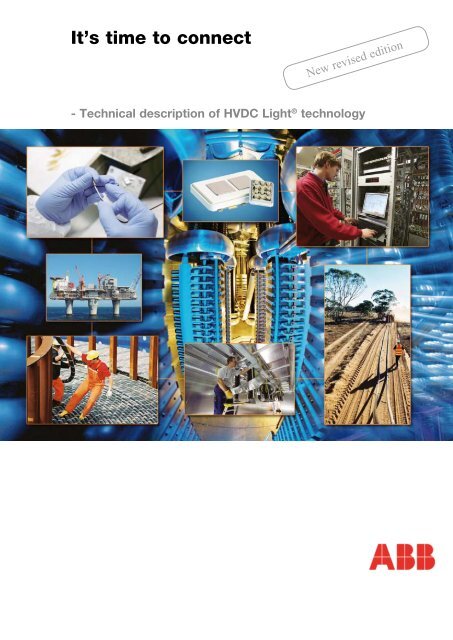
It’s time to connectNew revised edition- Technical description of <strong>HVDC</strong> <strong>Light</strong> ® technology
Table of Contents1. Introduction2. Applications3. Features4. Products5. Descriptions6. System engineering7. References8. IndexAfter the huge blackout in August 2003, a federal order allowed thefirst use of the Cross Sound Cable <strong>HVDC</strong> <strong>Light</strong> ® Interconnector.The cable interconnection made a major contribution to gettingLong Island out of the dark and restoring power to hundredsof thousands of customers across Long Island. LIPA ChairmanRichard Kessel heralded Cross Sound Cable as a “nationalsymbol of how we need to enhance our infrastructure”.ABB 3
Proven technology in new applicationsOur need for energy as a naturally integrated part of society is increasing,and electricity is increasing its share of the total energy used. It is truer thanever that electricity is a base for building a modern society, but also a principaltool for increasing well-being in developing countries. As a result, greaterfocus is directed at how the electricity is generated and distributed. In addition,society requests less environmental impact from transmission and generationalong with higher reliability and availability. To <strong>com</strong>bine these goalsthere is a need for new technologies for transmitting and distributing electricalenergy.In this book we present our response to these needs, the <strong>HVDC</strong> <strong>Light</strong> ® technique.<strong>HVDC</strong> <strong>Light</strong> ® makes invisible underground transmission systems technicallyand economically viable over long distances. The technology is alsowell suited for a number of applications such as power supply to offshore platforms,connecting offshore wind farms, improving grid reliability, city infeed andpowering islands. In these applications, specific characteristics of the technologysuch as <strong>com</strong>pact and light weight design, short installation and <strong>com</strong>missioningtime, low operation and maintenance costs and superior control of voltages,active and reactive power can be utilized.It is my true belief that the <strong>HVDC</strong> <strong>Light</strong> ® technique will actively contribute tothe development of transmission systems, in line with the requests given fromour society.March 2008Per HauglandSenior Vice PresidentGrid Systems4 ABB
INTRODUCTION1 Introduction1.0 Development of<strong>HVDC</strong> technology– historical backgroundDirect current was the first type oftransmission system used in the veryearly days of electrical engineering.Even though the AC transmissionsystem later on came to play avery important role, the developmentof DC transmission has always continued.In the 1930s, the striving formore and more power again raisedthe interest in high voltage DC transmissionas an efficient tool for thetransmission of large power volumesfrom remote localities. This initiatedthe development of mercury arc converters,and more than 20 years later,in 1954, the world’s first <strong>com</strong>mercial<strong>HVDC</strong> link based on mercury arcconverters went into service betweenthe Swedish mainland and the islandof Gotland. This was followed bymany small and larger mercury arcschemes around the world. Around20 years later, in the early 1970s, thethyristor semiconductor started toreplace the mercury converters.ABB has delivered more than 60<strong>HVDC</strong> projects around the worldproviding more than 48,000 MWcapacity. The largest bipole deliveredis 3150 MW.1.1 What is <strong>HVDC</strong> <strong>Light</strong> ® ?<strong>HVDC</strong> <strong>Light</strong> ® is the successful andenvironmentally-friendly way todesign a power transmission systemfor a submarine cable, an undergroundcable, using over head linesor as a back-to-back transmission.<strong>HVDC</strong> <strong>Light</strong> ® is <strong>HVDC</strong> technologybased on voltage source converters(VSCs). Combined with extruded DCcables, overhead lines or back-toback,power ratings from a few tenthsof megawatts up to over 1,000 MWare available. <strong>HVDC</strong> <strong>Light</strong> ® convertersare based on insulated gatebipolar transistors (IGBTs) and operatewith high frequency pulse widthmodulation in order to achieve highspeed and, as a consequence, smallfilters and independent control ofboth active and reactive power.<strong>HVDC</strong> <strong>Light</strong> ® cables have extrudedpolymer insulation. Their strengthand flexibility make them well suitedfor severe installation conditions,both underground as a land cableand as a submarine cable.The converter station designs arebased on voltage source convertersemploying state-of-the-art turn on/turnoff IGBT power semiconductors.<strong>HVDC</strong> <strong>Light</strong> ® has the capability torapidly control both active and reactivepower independently of eachother, to keep the voltage and frequencystable. This gives total flexibilityregarding the location of theconverters in the AC system, sincethe requirements for the short-circuitcapacity of the connected AC networkare low (SCR down to zero).The <strong>HVDC</strong> <strong>Light</strong> ® design is basedon a modular concept. For DC voltagesup to ± 150 kV, most of theequipment is installed in enclosuresat the factory. For the highest DCvoltages, the equipment is installedin buildings. The required sizes ofthe site areas for the converter stationsare also small. All equipmentexcept the power transformers isindoors.Well-proven and equipment testedat the factory make installation and<strong>com</strong>missioning quick and efficient.Installation of an <strong>HVDC</strong> <strong>Light</strong> ® stationABB 5
INTRODUCTION- Summary – Gotland <strong>HVDC</strong> <strong>Light</strong> ®For the Gotland scheme it was possibleto develop and implementpractical operational measuresthanks mainly to the experiencedflexibility of <strong>HVDC</strong> <strong>Light</strong> ® . Essentialaspects to consider were:• Flicker problems were eliminatedwith the installation of <strong>HVDC</strong> <strong>Light</strong> ® .Apparently, the transient voltagecontrol prevents the AC voltage fromlocking to the flicker.• Transient phenomena at whichfaults were dominant. This was themost significant problem.The parallel connection of <strong>HVDC</strong>with the AC grid and the weak gridin one station make the responsetime very important. Even the asynchronousgenerator behavior hasan impact during AC faults. It hasbeen shown that a standard voltagecontroller cannot be used to managethese situations. The parametersettings have to consider that thesystem must not be too fast in normaloperation, and that it has to actrapidly when something happens,which has been easily ac<strong>com</strong>plishedwith <strong>HVDC</strong> <strong>Light</strong> ® .Studies of fault events in the ACsystem have shown considerableimprovements in behavior bothduring the faults and at recovery,including improved stability.<strong>HVDC</strong> <strong>Light</strong> ® station in Näs, Gotland• Stability in the system.• Power flows, reactive powerdemands, as well as voltage levelsin the system. To meet the outputpower variation from the wind turbines,an automatic power flow controlsystem has been developed tominimize the losses and avoid overloadon the AC lines. In normal conditionsthe overall SCADA systemdetermines the set points for activeand reactive power to minimize thetotal losses in the whole system.This function is important, so thatthere is no need for the operators tobe on line and to carry out the controlmanually.Overall experiences are that thecontrol of the power flow from theconverters makes the AC grid easierto supervise than a conventionalAC network, and the power variationsdo not stress the AC grid asmuch as in normal networks. Voltagequality has also improved withthe increased wind power production.Sensitive customers, such asbig industrial <strong>com</strong>panies, now sufferless from disturbances due to voltagedips and other voltage qualityimperfections. Even if the networkcannot manage all AC faults, theaverage behavior over a year pointsto much better voltage quality.1.2.2 Directlink, Australia- Client needEnvironmentally-friendly power linkfor power trading between twostates in Australia.- ABB response3 x 60 MW <strong>HVDC</strong> <strong>Light</strong> ® convertersand 390 km (6 x 65 km) ± 80kV<strong>HVDC</strong> <strong>Light</strong> ® land cables.Project <strong>com</strong>missioned 2000.- Summary – DirectlinkDirectlink is a 180 MVA <strong>HVDC</strong> <strong>Light</strong> ®project, consisting of three parallel60 MVA transmission links that connectthe regional electricity marketsof New South Wales and Queensland.Directlink is a non-regulatedproject, operating as a generatorby delivering energy to the highestvalue regional market.The Directlink project features threeinnovations which minimize its environmental,aesthetic and <strong>com</strong>mercialimpact: the cable is buriedunderground for the entire 65 km;it is an entrepreneurial project thatwas paid for by its developers, andthe flow of energy over <strong>HVDC</strong> <strong>Light</strong> ®facilities can be precisely definedand controlled. The voltage sourceconverter terminals can act independentlyof each other to provideancillary services (such as VAR support)in the weak networks to whichDirectlink connects.Experience with the operation ofDirectlink with three parallel linksstarted in the middle of 2000 andconfirms the expected excellentbehavior of the controllability of thetransmission.ABB 7
INTRODUCTION1.2.3 Tjæreborg, Denmark- Client needA small-scale <strong>HVDC</strong> <strong>Light</strong> ® systemto be used for testing optimal transmissionfrom wind power generation.- ABB response8 MVA <strong>HVDC</strong> <strong>Light</strong> ® converters and9 km (2 x 4.5 km) ± 9 kV <strong>HVDC</strong> <strong>Light</strong> ®land cables. Project <strong>com</strong>missioned2000.- Summary – Tjæreborg<strong>HVDC</strong> <strong>Light</strong> ®The purpose of the Tjæreborg <strong>HVDC</strong>project was to investigate how thecontrollability of <strong>HVDC</strong> <strong>Light</strong> ® couldbe used for optimal exploitation ofthe wind energy by using the converterto provide a collective variablefrequency to the wind turbines. TheTjæreborg wind farm can either beconnected via the AC transmissiononly, or via the DC transmission only,or via the AC and the DC cables inparallel. The <strong>HVDC</strong> <strong>Light</strong> ® controlsystem is designed to connect viathe AC transmission automatically ifthe wind power production is below500 kW, and via the DC cables if thepower is higher than 700 kW.Experience has been gained of thesuccessful use of <strong>HVDC</strong> <strong>Light</strong> ® for:• Starting and stopping the wind turbinesat low and high wind speeds.• Smooth automatic switchingbetween the AC and DC transmissionby automatically synchronizingthe wind turbines to the AC grid.• Start against black network. Thiswas tested, as an isolated AC grid,e.g. an islanded wind farm has to beenergized from the DC transmission.• With a connected wind turbinegenerator, the frequency was variedbetween 46 and 50 Hz. A separatetest without connected wind turbinesdemonstrated that the <strong>HVDC</strong><strong>Light</strong> ® inverter frequency could bevaried between 30 Hz and 65 Hzwithout any problems.The Tjæreborg <strong>HVDC</strong> <strong>Light</strong> ® stationDirectlink <strong>HVDC</strong> <strong>Light</strong> ® station 3 x 60 MW8 ABB
INTRODUCTION1.2.4 Eagle Pass, US- Client needStabilization of AC voltage and possibilityto import power from Mexicoduring emergencies.- ABB response36 MVA <strong>HVDC</strong> <strong>Light</strong> ® back-to-backconverters. Project <strong>com</strong>missioned2000.- Summary – Eagle Pass<strong>HVDC</strong> <strong>Light</strong> ® back-to-back waschosen since other alternativeswould have been more expensive,and building a new AC line wouldhave faced the added impedimentof having to over<strong>com</strong>e difficultiesin acquiring the necessary rightsof way. Furthermore, if an <strong>HVDC</strong>back-to-back based on conventionaltechnology had been considered,there were concerns that such asolution might not provide the necessarylevel of reliability because ofthe weakness of the AC system onthe U.S. side of the border.To mitigate possible voltage instabilityand, at the same time, to allowpower exchange in either directionbetween the U.S. and Mexico withoutfirst having to disrupt service todistribution system customers, an<strong>HVDC</strong> <strong>Light</strong> ® back-to-back rated at36 MVA at 138 kV was installed and<strong>com</strong>missioned.1.2.5 Cross Sound Cable, US- Client needEnvironmentally-friendly controllablepower transmission to Long Island.- ABB response330 MW MW <strong>HVDC</strong> <strong>Light</strong> ® convertersand 84 km (2 x 42 km) ±150 kV<strong>HVDC</strong> <strong>Light</strong> ® submarine cables.Project <strong>com</strong>missioned 2002.The two <strong>HVDC</strong> <strong>Light</strong> ® power cablesand the multi-fiber optic cable werelaid bundled together to minimizethe impact on the sea bottom and toprotect oysters, scallops and otherliving species. The cables were buriedsix feet into the sea floor to giveprotection against fishing gear andships’ anchors. The submarine FiberOptic cable is furnished with 192fibers.- Summary – Cross Sound CableThe Cross Sound Cable project isa 42 km <strong>HVDC</strong> <strong>Light</strong> ® transmissionbetween New Haven, Connecticutand Shoreham on Long Islandoutside New York. It provides thetransmission of electric energy toLong Island. The rating is 330 MWwith the possibility of both local andremote control.Testing of the Cross Sound Cableproject was <strong>com</strong>pleted in August2002. The big blackout in the northeasternstates happened on August14 2003, and the Cross Soundtransmission became an importantpower supply route to Long Islandwhen restoring the network duringthe blackout.Some hours after the blackout, afederal order was given to startemergency operation. In addition toproviding power to Long Island, theAC voltage control provided by thelink of both the Long Island and theConnecticut networks showed thatit could keep the AC voltages constant.During the thunderstorms thatoccurred before the networks were<strong>com</strong>pletely restored, several +100to –70 Mvar swings were noticedover 20 seconds. AC voltage waskept constant. The transmissionremained in emergency operationduring the fall of 2003. The ownerhas concluded that the cable interconnectionmade a major contributionto getting Long Island out of thedark and restoring power to hundredsof thousands of customersacross Long Island.<strong>HVDC</strong> <strong>Light</strong> ® station at ShorehamSteady-State 100 MW CT —> LIduring thunderstorm. ACVC APC SHM.Measurement in Shoreham ConverterStation (DASH-18) Sunday 17 August2003 – 18:48:00.000ABB 9
INTRODUCTION1.2.6 MurrayLink, Australia- Client needEnvironmentally-friendly power linkfor power trading between twostates in Australia.- ABB response200 MW <strong>HVDC</strong> <strong>Light</strong> ® convertersand 360 km (2 x 180 km) ±150 kV<strong>HVDC</strong> <strong>Light</strong> ® land cables. Project<strong>com</strong>missioned 2002.- Summary – MurrayLinkMurrayLink is a 180 km underground200 MW transmission systembetween Red Cliffs, Victoria andBerry, South Australia. It links regionalelectricity markets and uses the abilityof <strong>HVDC</strong> <strong>Light</strong> ® technology to controlpower flow over the facility. Thevoltage source converter terminalscan act independently of each otherto provide ancillary services (such asvar support and voltage control) inthe weak networks to which it is connected.Operating experience is thatits AC voltage control considerablyimproves voltage stability and powerquality in the connected networks. Inaddition, shunt reactors in neighboringnetworks can normally be disconnectedwhen the link’s AC voltagecontrol is on.On the loss of an AC line, there is arun-back from 200 MW to zero.The project has won the CaseEARTH Award for EnvironmentalExcellence.Cable transport for MurrayLink projectCable laying for MurrayLink project10 ABB
INTRODUCTION1.2.7 Troll A, Norway- Client needEnvironmentally-friendly electricpower to feed <strong>com</strong>pressors toincrease the natural gas productionof the platform, <strong>com</strong>bined with littleneed of manpower for operation.- ABB response2 x 40 MW <strong>HVDC</strong> <strong>Light</strong> ® convertersand 272 km (4 x 68 km) ±60kV <strong>HVDC</strong> <strong>Light</strong> ® submarine cables.Project <strong>com</strong>missioned 2005.- Summary – Troll AWith the Troll A pre-<strong>com</strong>pressionproject, <strong>HVDC</strong> transmission convertersare, for the first time, beinginstalled offshore on a platform. Thetransmission design for this firstimplementation is for 40 MW,±60 kV, and converters for twoidentical transmissions have beeninstalled and tested. On the Troll Aplatform, the <strong>HVDC</strong> <strong>Light</strong> ® transmissionsystem will directly feed a highvoltagevariable-speed synchronousmachine designed for <strong>com</strong>pressordrive with variable frequency andvariable voltage, from zero to maxspeed (0-63 Hz) and from zero tomax voltage (0-56 kV).The inverter control software hasbeen adapted to perform motorspeed and torque control. The controlhardware is identical for rectifierand motor converters.Over the entire motor operatingrange, unity power factor and lowharmonics are assured, while sufficientlyhigh dynamic response isalways maintained. There is no tele<strong>com</strong>municationfor control betweenthe rectifier control on land and theinverter motor control on the platform- the only quantity that can bedetected at both ends of the transmissionis the DC-link voltage.However, the control system hasbeen designed so that, together witha tele<strong>com</strong>munication link, it couldprovide for land-based operation,faultfinding and maintenance of theplatform station.ABB 11
INTRODUCTION1.2.8 Estlink <strong>HVDC</strong> <strong>Light</strong> ® link,Estonia - Finland- Client needImproved security of the electricitysupply in the Baltic States and Finland.Reduced dependence of the Balticpower systems and an alternativeelectricity purchase channel tocover potential deficits in generatingcapacity.- ABB response350 MW <strong>HVDC</strong> <strong>Light</strong> ® converters and210 km (2 x 10⁵ km) ± 150 kV <strong>HVDC</strong><strong>Light</strong> ® ‚ submarine/land cables. Project<strong>com</strong>missioned 2006.- Summary – EstlinkEstlink is a 350 MW, 31 km underground/74 km submarine cabletransmission between the Harkusubstation in Estonia and Espoosubstation in Finland. It links theBaltic power system to the Nordpoolmarket and uses the ability of<strong>HVDC</strong> <strong>Light</strong> ® technology to controlthe power flow over the facility. Thevoltage source converter terminalscan act independently of each otherto provide ancillary services (suchas var support and voltage control),thereby improving the voltage stabilityof the Estonian grid. The blackstartcapability is implemented atthe Estonian side i.e. the converteris automatically switched to householdoperation if the AC grid is lostmaking a fast energization of thenetwork possible after a blackoutin the Estonian network. The implementationphase of the project was19 months, and the link has been inoperation since the end of 2006.The <strong>HVDC</strong> <strong>Light</strong> ® station at Harku on the Estonian side of the link.12 ABB
INTRODUCTION1.2.9 Valhall Re-developmentProject- Client needSupply of electric power from shore,to replace existing gas turbinesoffshore and feed the entire existingfield, as well as a new platform.The important issues are to minimizeemissions of CO 2and other climategases and, at the same time, toreduce the operating and maintenancecosts of electricity offshore.- ABB response<strong>HVDC</strong> <strong>Light</strong> ® converter stationsonshore and offshore rated 78 MWat 150 kV. The project will be <strong>com</strong>missioned2009.- Summary - ValhallRe-development projectAs a part of the redevelopment of theValhall field in the Norwegian sector,ABB will provide the converter stationsto enable 78 MW to be suppliedover a distance of almost 300 km fromshore to run the entire field facilities,including a new production and livingquarters platform.The main factors behind the decisionto choose power from shore were:- reduced costs- improved operational efficiency- minimized greenhouse gas emissions- improvement of all HSE elementsThese factors contribute to the customerBP’s vision of a safe, intelligent,maintenance-free and remotely controllablefield of the future. In addition,the <strong>HVDC</strong> <strong>Light</strong> ® system will providea very high quality electric supplywith respect to voltage and frequency,including during direct onlinestart-up of the large gas <strong>com</strong>pressormotors, thereby eliminating the needfor additional soft start equipment.The onshore station will be locatedat Lista on Norway’s southern coast.Here the alternating current will betaken from the Norwegian grid at300 kV and converted to direct current.This will be transmitted at 150 kVover a distance of 292 km via a singlepower cable with an integratedmetallic return conductor to the newValhall platform. There it will be convertedback to AC power at 11 kVin the <strong>HVDC</strong> module and distributed toall the platforms in the Valhall field.Valhall Power from shore projectOffshore Station, ValhallABB 13
INTRODUCTION1.2.10 NordE.ON 1 offshorewind connection - Germany- Client needA 200 km long submarine/land cableconnection from an offshore wind parkto be operational within 24 months.- ABB response400 MW <strong>HVDC</strong> <strong>Light</strong> ® converters,one offshore on a platform and oneland-based and 400 km (2 x 200km) ±150 kV <strong>HVDC</strong> <strong>Light</strong> ® submarine/landcables. The project will be<strong>com</strong>missioned 2009.- Summary - NordE.ON 1 offshorewind connectionThe NordE.ON 1 offshore wind farmcluster will be connected to the Germangrid by a 400 MW <strong>HVDC</strong> <strong>Light</strong> ®transmission system, <strong>com</strong>prising 75km underground and 128 km submarinecable. Full Grid Code <strong>com</strong>plianceensures a robust network connection.For both the offshore and the onshorepart, most equipment will be installedindoors, thus ensuring safe operationand minimal environmental impact.Independent control of active andreactive power flow with total controlof power from zero to full power withoutfilter switching enables smoothand reliable operation of the offshorewind farm.A proven extruded cable technologyis used that simplifies installation onland and at sea allowing very shorttime for cable jointing. The oil-free<strong>HVDC</strong> <strong>Light</strong> ® cables minimize theenvironmental impact at sea and onland.In operation, the wind power projectwill reduce CO 2emissions by nearly1.5 million tons per year by replacingfossil-fuel generation.The transmission system supportswind power development in Germany.1.2.11 Caprivi LinkInterconnector- Client needImport of hydro power and coalfiredpower from Zambia to ensurea secure power supply in Namibiautilizing an <strong>HVDC</strong> <strong>Light</strong> ® interconnectionof two weak AC networksthrough a 970 km long ±350 kVoverhead line.In addition:- Accurate AC voltage control ofthe weak interconnected ACnetworks.- Feed of a passive AC network inthe Caprivi strip.- ABB response<strong>HVDC</strong> <strong>Light</strong> ® converter stationsdesigned for a DC voltage of±350 kV to ground, to be builtin two stages:- first stage: a monopole 300 MW(-350 kV to ground)- second stage: an upgrade to2 x 300 MW bipole (±350 kV).The monopole will be put into operationat the end of year 2009. Electrodestations about 25 km from theconverter stations.- Summary – Caprivi LinkInterconnectorThe Caprivi Link Interconnector willbe a 2 x 300 MW interconnectionbetween the Zambezi converter stationin the Caprivi strip in Namibia,close to the border of Zambia,and the Gerus converter station,about 300 km North of Windhoekin Namibia. The AC voltages are320 kV and 400 kV at Zambezi andGerus respectively.The converter stations will be interconnectedby a 970 km long, bipolar±350 kV DC overhead line. Theconductors of both the negativeand positive polarity will be mountedon the same poles. There will bedouble-circuit electrode lines with alength of about 25 km.The NordE.ON 1 offshore wind connection14 ABB
INTRODUCTIONIn the monopole stage, the link willbe operated with parallel DC linesand earth return to reduce line losses.In the bipole stage, the link willbe operated as a balanced bipolewith zero ground current.The AC networks of today areextremely weak at both ends, withshort-circuit power levels of around300 MVA and long AC lines whichconnect to remote generator stations.Due to this fact, the AC networksare also exposed to a risk of50 Hz resonance. ABB has studiedthe crucial AC and DC fault casesand verified that the dynamic performanceof the <strong>HVDC</strong> <strong>Light</strong> ® is in linewith the requirements of the client.The condition for the upgrade to a2 x 300 MW bipole is that the ACnetworks at Zambezi and Gerus arereinforced, including a new connectionto the Hwange coal fired powerstation in Zimbabwe.The Zambezi and Gerus converterstations will control the AC voltagesin the surrounding grids rapidly andaccurately over the entire range ofactive power capability, by a continuousadjustment of the reactive powerabsorption and generation between- 130 Mvar and + 130 Mvar.In the event of outage of the connectingAC lines to Zambezi duringpower import to Namibia, the powertransmission can be reversed rapidlyin order to re-energize and feed theblack AC network at Zambezi.The client evaluated possible transmissionalternatives and found thatthe <strong>HVDC</strong> <strong>Light</strong> ® technology is themost feasible economically andtechnically solution.The Caprivi LinkInterconnectorStation Layout, Caprivi Link InterconnectorABB 15
APPLICATIONS2 Applications2.1 GeneralA power system depends on stableand reliable control of active andreactive power to keep its integrity.Losing this control may lead toa system collapse. Voltage sourceconverter (VSC) transmission systemtechnology, such as <strong>HVDC</strong><strong>Light</strong> ® , has the advantage of beingable almost instantly to change itsworking point within its capability,and to control active and reactivepower independently. This can beused to support the grid with thebest mixture of active and reactivepower during stressed conditions.In many cases, a mix of active andreactive power is the best solution<strong>com</strong>pared with active or reactivepower only. VSC transmissionsystems can therefore give addedsupport to the grid.As an example, simulations done atABB have shown that, for a parallelcase (AC line and DC transmission),where the VSC transmissionsystem is connected in parallel withan AC system, the VSC transmissionsystem can damp oscillations2-3 times better than reactive shunt<strong>com</strong>pensation.The benefits with a VSC transmissionsystem during a grid restorationcan be considerable, since itcan control voltage and stabilize frequencywhen active power is availableat the remote end. The frequencycontrol is then not limitedin the same way as a conventionalpower plant where boiler dynamicsmay limit the operation during gridrestoration.With the above benefits, <strong>HVDC</strong><strong>Light</strong> ® is the preferred system tobe used for a variety of transmissionapplications, using submarinecables, land cables and back-toback.2.2 Cable transmission systems2.2.1 Submarine cables- Power supply to islandsThe power supply to small islandsis often provided by expensive localgeneration, e.g. diesel generation.By installing an <strong>HVDC</strong> <strong>Light</strong> ® transmissionsystem, electricity from themainland grid can be imported.Another issue is the environmentalbenefits to the island by reducingemission from local generation.Since <strong>HVDC</strong> <strong>Light</strong> ® is based on VSCtechnology, the converter can operatewithout any other voltage sourceon the island, i.e. no local generationon the island is needed for properoperation of the system.- Remote small-scale generationRemote small-scale generating facilitiesare very often located on islandsthat will not need all the generatedpower in all situations. This powercan then be transmitted by <strong>HVDC</strong><strong>Light</strong> ® to a consumer area on themainland or an adjacent island.- Interconnecting power systemsThe advantages of <strong>HVDC</strong> <strong>Light</strong> ®are of high value when connectingbetween individual power systems,especially when they are asynchronous.This refers to the possibilitiesfor controlling the transmitted powerto an undertaken value, as well asbeing able to provide and controlreactive power and voltage in boththe connected networks.- Power to/from/between OffshoreplatformsWith its small footprint and its possibilitiesto operate at low short-circuitpower levels or even to operate witha “black” network, <strong>HVDC</strong> <strong>Light</strong> ® hasmade it possible to bring electricity:- from the shore to the platform- from platform to shore- between platformsThe most important and desirablecharacteristics for offshore platforminstallations are the low weight andvolume of the <strong>HVDC</strong> <strong>Light</strong> ® converter.Offshore, the converter is locatedinside a module with a controlledenvironment, which makes it possibleto design the converter evensmaller for an offshore installationthan for a normal onshore converterstation.2.2.2 Underground cables- InterconnectionsThe environmental advantages of<strong>HVDC</strong> <strong>Light</strong> ® are of high value whenconnecting two power systems. Thisrefers to the possibilities for controllingthe transmitted power to thedesired value, as well as improvingAC network stability by providing andcontrolling reactive power and voltagesupport in the connected networks.Other important factors are:avoiding loop flows, sharing of spinningreserve, emergency power etc.The rapid AC voltage control by<strong>HVDC</strong> <strong>Light</strong> ® converters can also beused to operate the connected ACnetworks close to their maximumpermitted AC voltage and in this wayto reduce the line losses in the connectedAC networks.16 ABB
APPLICATIONS- BottlenecksIn addition to the power transmitted bythe <strong>HVDC</strong> <strong>Light</strong> ® system, an <strong>HVDC</strong><strong>Light</strong> ® transmission in parallel withan existing AC line will increase thetransmitting capacity of the AC lineby the inherent voltage support andpower stabilizing capability of the<strong>HVDC</strong> <strong>Light</strong> ® system.- Infeed to citiesAdding new transmission capacityvia AC lines into city centers is costlyand in many cases the permitsfor new right-of-ways are difficult toobtain. An <strong>HVDC</strong> <strong>Light</strong> ® cable needsless space than an AC overhead lineand can carry more power than anAC cable, and therefore it is oftenthe only practical solution, shouldthe city center need more power.Also, the small footprint of the <strong>HVDC</strong><strong>Light</strong> ® converter is of importance forrealizing city infeed. Another benefitof <strong>HVDC</strong> <strong>Light</strong> ® is that it does notincrease the short-circuit current inthe connected AC networks.2.3 DC OH lines<strong>HVDC</strong> <strong>Light</strong> ® converters can operatein <strong>com</strong>bination with DC overheadlines forming a proper transmissionsystem. An example of thisis the Caprivi Link Interconnector inNamibia.- see 1.2.112.4 Back-to-backA back-to-back station consists oftwo <strong>HVDC</strong> <strong>Light</strong> ® converters locatedclose to each other, i.e. with no DCcables in between.2.4.1 Asynchronous ConnectionIf the AC network is divided into differentasynchronous areas, connectionbetween the areas can easilybe done with <strong>HVDC</strong> back-to-backconverters. This gives a number ofadvantages:- Sharing of spinning reserve.- Emergency power exchangebetween the networks- Better utilization of installed generationin both networks- Voltage support- etc.In many cases, the connectionbetween two asynchronous areasis made at a weak connection pointin AC systems on the borders ofthe areas. With its possibilities ofoperating at low short-circuit ratios,<strong>HVDC</strong> <strong>Light</strong> ® is very suitable for thistype of connection.2.4.2 Connection of importantloadsFor sensitive loads, an <strong>HVDC</strong> <strong>Light</strong> ®back-to-back system is of importancefor keeping the AC voltageand AC frequency on proper levels ifthe quality of those properties of theconnected AC network is not sufficientfor the connected load. Thefast reactive power control propertiesof <strong>HVDC</strong> <strong>Light</strong> ® can be used forflicker mitigation.2.5 <strong>HVDC</strong> <strong>Light</strong> ® and windpower generation<strong>HVDC</strong> <strong>Light</strong> ® is a transmission systemwhich has characteristics suitablefor connecting large amountsof wind power to networks, even atweak points in a network, and withouthaving to improve the short-circuitratio.This is contrary to conventional ACtransmission systems, which normallyrequire a high SCR <strong>com</strong>pared withthe power to be entered. With theimminent arrival of wind power farmsand accounting for a considerableshare of the total power generationin a network, wind power farms willhave to be as robust as conventionalpower plants and stay online duringvarious contingencies in the AC network.Various types of <strong>com</strong>pensationwill then be needed to preservepower quality and/or even the stabilityof the network.<strong>HVDC</strong> <strong>Light</strong> ® does not require anyadditional <strong>com</strong>pensation, as thisis inherent in the converters. It willtherefore be an excellent tool forbringing wind power into a network2.6 Comparison of AC, conventional<strong>HVDC</strong> and <strong>HVDC</strong> <strong>Light</strong> ®- Comparison of DC cable systemand AC cable systemDC cable system- No limit on cable length- No intermediate station needed- No increase of capacitance in theAC network (avoids low-order resonances)- Lower lossesAC cable system- Cable capacitance limits the practicalcable length- Reactive <strong>com</strong>pensation is neededABB 17
APPLICATIONSComparison of <strong>HVDC</strong> <strong>Light</strong> ® and conventional <strong>HVDC</strong>- <strong>HVDC</strong> <strong>Light</strong> ® , power from50 – 1100 MWIGBT used as active <strong>com</strong>ponentin valvesThe pulse width controls bothactive and reactive power- Each terminal is an <strong>HVDC</strong>converter plus an SVC- Suitable both for submarine andland cable connections- Advanced system features- Footprint (e.g. 550 MW):120 x 50 x 11 meters- Short delivery time- Multi-chip design- Forward blocking only- Current limiting characteristics- Gate turn-off and fully controllable;forced <strong>com</strong>mutation- High-speed device- The IGBT can be switched off witha control signal. Fully controllable.= forced <strong>com</strong>mutation up to 2000 Hz- Conventional <strong>HVDC</strong>, power upto 6400 MWThyristor used as active<strong>com</strong>ponent in valvesPhase angle controlPmaxPmin- The thyristor cannot be switchedoff with a control signal.- Most economical way to transmitpower over long distances.- Long submarine cableconnections.- Around three times more power ina right-of-way than overhead AC- Footprint (e.g. 600 MW):200 x 120 x 22 meters- Single silicon wafer- Both forward and reverse blockingcapability- Very high surge current capability- No gate turn-off; line <strong>com</strong>mutated- It automatically ceases to conductwhen the voltage reverses.= line <strong>com</strong>mutated, 50/60 Hz18 ABB
APPLICATIONS - Upper trace: Reactor voltage- Middle trace: Valve voltage- Lower trace: DC Voltage<strong>HVDC</strong> <strong>Light</strong> ® deep sea cables600.00KCLASSIC CONVERTER 03 .CIR0.00K-400.00K800.00K0.00m 80.00m 100.00mv(trafo1)-v(neutral)T0.00K-200.00K675.00K0.00m 80.00m 100.00m-v(R11)T0.00K0.00m 80.00m 100.00mv(dc1)-v(dc2)T- Upper trace: Transformer voltage- Middle trace: Valve voltageMass impregnated <strong>HVDC</strong> cable- Lower trace: DC voltageABB 19
APPLICATIONS- Simplified single-line diagram for <strong>HVDC</strong> <strong>Light</strong> ®DC capacitor- Simplified single-line diagram for conventional <strong>HVDC</strong>20 ABB
APPLICATIONS- An <strong>HVDC</strong> <strong>Light</strong> ® can control both active and reactive power2.7 Summary of drivers forchoosing an <strong>HVDC</strong> <strong>Light</strong> ®application2.7.1 AC Network SupportOperating area- Active and reactive power independentlyand rapidly controlled - Operation down to short-circuitratios of zero - Loop flows of power are avoided- Black start is possible- Stabilization of connected AC grids Y-axis : active power- Reactive power exchange for conventional <strong>HVDC</strong> - Sharing spinning reserve betweenareas- Continuously variable power fromfull power in one direction to fullpower in reverse- Emergency power support- Increase power in parallel AC lines- No <strong>com</strong>mutation failures- Multi-terminal system simple- No minimum power - can operatedown to zero power- Additional reactive shunt <strong>com</strong>pensationis not required. (Only smallharmonic filters are needed.)- Only conventional AC transformersare requiredQO,1, PUnbalance- The <strong>HVDC</strong> <strong>Light</strong> ® control can bedesigned so that the <strong>HVDC</strong> <strong>Light</strong> ®stations can eliminate flicker andselected harmonics in the AC grid.- The <strong>HVDC</strong> <strong>Light</strong> ® stations can beoperated as STATCOMs, even ifthe <strong>HVDC</strong> <strong>Light</strong> ® Station is notconnected to the DC line (stagedimplementation: build one or twostations for voltage stabilization– connect them later with cablesand you have an interconnection).ABB 21
APPLICATIONS2.7.2 Undergrounding by cables- No visible impact of overhead lines– underground cables instead- Easier to get permission- No relevant electromagnetic fields- No audible noise, unlike OH lines2.7.3 Required site area forconverters- Less space per MW required thanfor conventional <strong>HVDC</strong>- Indoor design - reduced risk offlashover- Small space requirement and lowweight are very important for offshoreapplications2.7.4 Environmentally sound- Audible sound reduced by indoordesign- Stations look like any ordinaryindustrial building, no outdoorswitchyards- Low building height- Bipolar operation – no need forelectrodes2.7.5 Energy trading- Fast and accurate power control –you get the power you want- No filter switching at power change- Smooth power reversal (step lesspower transfer around zero MW)2.8 <strong>HVDC</strong> <strong>Light</strong> ® cables2.8.1 Long lifetime with <strong>HVDC</strong>The inherent lifetime of insulatingmaterials is better for <strong>HVDC</strong> thanfor AC.2.8.2 Submarine cables- Low losses<strong>HVDC</strong> cables are generally muchmore efficient for long-distancetransmissions than AC cables, inparticular for high powers.The reason is that AC cables mustbe rated for the capacitive chargingcurrent, in addition to the transmittedactive current. The capacitivecharging current is proportional tothe length and the voltage of the ACcable and beyond a certain distancethere is no capacity left for the activepower transmission. DC cables haveno capacitive charging current, i.e.all the transmission capacity of thecable is available for active powertransmission. The capacitive reactivepower generated by long AC cablesmust be taken care of.To avoid ferromagnetic losses ACsubmarine cables need non-magneticmaterial for the wire armor,thus copper or aluminum alloy ornon-magnetic stainless steel wiresare used.For DC cables, there are no magneticlosses, hence galvanized steelwires, can be used for the tensilearmor.The following example shows thedifference:Transmission of 550 MW by submarinecables for a distance of 75 km:<strong>HVDC</strong> cable:150 kV <strong>HVDC</strong> <strong>Light</strong> ® cables, 2cables with copper conductorcross-section of 1400 mm2 andsteel wire tensile armor. The weightof the two cables is 2 x 32 kg/m =64 kg/m.AC cable:220 kV XLPE cable, 3 cables withcopper conductor cross-sectionof 1600 mm 2 and copper wire tensilearmor. The weight of the threecables is 3 x 60 kg/m = 180 kg/m.- Deep sea waters<strong>HVDC</strong> <strong>Light</strong> ® cables are suitable forlarge water depths, for the followingreasons:- The polymeric insulation ismechanically robust.- The <strong>HVDC</strong> cables are generallyless heavy than AC cables forthe same transferred power. Thisgives lower tensile force duringlaying of the cables.- It is advantageous to use galvanizedsteel wires for tensile armor.A galvanized steel wire has bettertensile properties than mostnon-magnetic materials that canbe used.22 ABB
APPLICATIONS- Laying and repair<strong>HVDC</strong> <strong>Light</strong> ® cables are very flexiblewith respect to various installationmethods, due to their robust andflexible insulation material. Should arepair be required, the availability ofsuitable cable ships is thus good.- The cable can be coiled on acable laying ship (except forcables with double cross laidarmor for large depths). The possibilityof coiling the cables makesit possible to lay the cable fromsmall barges and transport thecable by cargo ships without turntablesfor the cables.- It is possible in most cases to laythe two cables of the bipole closeto each other (e.g. by bundling ofthe cables) in one <strong>com</strong>mon trench.- The bending radius of the polymericinsulated <strong>HVDC</strong> <strong>Light</strong> ® cableis smaller <strong>com</strong>pared with paperinsulatedcables, which makes itpossible to use laying ships witha smaller pay-off wheel, and alsosmaller trenching equipment.Typical laying and trenching operation- Good resistance when installedParticularly when <strong>com</strong>paring withpaper-oil insulated cables, the <strong>HVDC</strong><strong>Light</strong> ® cables can resist repeatedbending without fatigue of theinsulation. This is critical for cableshanging in spans over an unevensea bed.Coiled cable on small cable laying bargeABB 23
APPLICATIONS2.8.3 Underground Cables- PermittingIn many cases it is easier to getright of way for underground cables,<strong>com</strong>pared with overhead transmissionlines. The main reasons are:- Less visual impact- Smaller width of the required rightof way.- Handling<strong>HVDC</strong> <strong>Light</strong> ® cables have manyadvantages <strong>com</strong>pared with othercable types, e.g.:- <strong>HVDC</strong> <strong>Light</strong> ® cables have smallerbending radius <strong>com</strong>paredwith paper insulated cables. Thismakes it possible to use smallercable drums for transportation,and makes it possible to use <strong>com</strong>pactinstallation, e.g. on offshoreplatforms. The smaller bendingradius also makes it possible to goaround obstacles such as rocks,etc.- <strong>HVDC</strong> <strong>Light</strong> ® cables are possibleto handle at lower temperatures<strong>com</strong>pared with paper insulatedcables.- Minimum bending radius forstandard designsDuring installation, the bending radiusshould exceed 18 x D e.When the cable is installed (no forceapplied to the cable), the bendingradius must exceed 12 x D e.D eis the external diameter of the cable.- Maximum pulling forces for landcablesWhen the pulling nose is attached tothe conductor, the following tensileforces should not be exceeded:- 70 N/mm 2 for Cu conductors- 40 N/mm 2 for Al conductors- Jointing<strong>HVDC</strong> <strong>Light</strong> ® cable joints are usuallyinstalled inside a portable jointinghouse, which is placed in the jointbay. This pre-built jointing houseprovides adequate light, dust control,clean work surfaces and cablestands to place the joint within <strong>com</strong>fortablereach of the cable jointers.A crew of two cable jointers usuallyworks together as a team. A jointcrew can <strong>com</strong>plete one of thesejoints in one working day.- No magnetic fields of power frequencyThere is no power frequency magneticfield from a DC cable; there isonly a static magnetic field, similar tothe earth’s magnetic field.Re<strong>com</strong>mended levels of static magneticfield strength are significantlyhigher than for power frequencyfields (from AC power lines), sincethere is no induction effect, and themagnetic fields are similar to that ofthe earth itself.A conventional mono-polar <strong>HVDC</strong>cable scheme with a current of 1000amps gives a magnetic field of 20micro-Tesla magnitude at a distanceof 10 meters. This is approximatelyhalf the magnitude of the earth’s naturalmagnetic field. With <strong>HVDC</strong> <strong>Light</strong> ®Cables, the magnetic field is reducedto less than 0.2 micro-Tesla, whichis less than 1% of the natural magnetism.Jointing container, placed over thecables during jointing at MurrayLink.24 ABB
FEATURES3 Features3.1 Independent power transferand power quality controlThe <strong>HVDC</strong> <strong>Light</strong> ® system allowsfully independent control of boththe active and the reactive powerflow within the operating range ofthe <strong>HVDC</strong> <strong>Light</strong> ® system. The activepower can be continuously controlledfrom full power export to fullpower import. Normally each stationcontrols its reactive power flowindependently of the other station.However, the flow of active powerto the DC network must be balanced,which means that the activepower leaving the DC network mustbe equal to the active power <strong>com</strong>inginto the DC network, minus thelosses in the <strong>HVDC</strong> <strong>Light</strong> ® system. Adifference in power would imply thatthe DC voltage in the system wouldrapidly increase or decrease, as theDC capacitor increases its voltagewith increased charge. In a normaldesign, the stored energy is equivalentto around 2 ms power transmissionon the system. To attain thispower balance, one of the stationscontrols the DC voltage.This means that the other stationcan arbitrarily adjust the transmittedpower within the power capabilitylimits of the <strong>HVDC</strong> <strong>Light</strong> ® system,whereby the station that controlsthe DC voltage will adjust its powerto ensure that the balance (i.e. constantDC voltage) is maintained. Thebalance is attained without tele<strong>com</strong>municationbetween the stations,quite simply based on measurementof the DC voltage.3.2 Absolute and predictablepower transfer and voltage controlThe active power flow can be determinedeither by means of an activepower order or by means of frequencycontrol.The converter stations can be set togenerate reactive power through areactive power order, or to maintaina desired voltage level in the connectedAC network.The converter’s internal control loopis active and reactive current, controlledthrough measurement of thecurrent in the converter inductor andusing orders from settings of activeand reactive power which an operatorcan make.In an AC network, the voltage ata certain point can be increased/reduced through the generation/consumption of reactive power. Thismeans that <strong>HVDC</strong> <strong>Light</strong> ® can controlthe AC voltage independently ineach station.3.3 Low power operationUnlike conventional <strong>HVDC</strong> converters,the <strong>HVDC</strong> <strong>Light</strong> ® converter canoperate at very low power, and evenat zero power. The active and reactivepowers are controlled independently,and at zero active power thefull range of reactive power can beutilized.3.4 Power reversalThe <strong>HVDC</strong> <strong>Light</strong> ® transmission systemcan transmit active power inany of the two directions with thesame control setup and with thesame main circuit configuration. Thismeans that an active power transfercan be quickly reversed withoutany change of control mode, andwithout any filter switching or converterblocking. The power reversalis obtained by changing the directionof the DC current and not bychanging the polarity of the DC voltageas for conventional <strong>HVDC</strong>. Thespeed of the reversal is determinedby the network. The converter couldreverse to full power in millisecondsif needed.The reactive power controller operatessimultaneously and independentlyin order to keep the orderedreactive power exchange unaffectedduring the power reversal.3.5 Reduced power losses inconnected AC systemsBy controlling the grid voltage level,<strong>HVDC</strong> <strong>Light</strong> ® can reduce losses inthe connected grid. Both transmissionline ohmic losses and generatormagnetization losses can bereduced. Significant loss reductionscan be obtained in each of the connectednetworks.3.6 Increased transfer capacityin the existing system- Voltage increaseThe rapid and accurate voltage controlcapability of the <strong>HVDC</strong> <strong>Light</strong> ®converter makes it possible to operatethe grid closer to the upper limit.Transient overvoltages would becounteracted by the rapid reactivepower response. The higher voltagelevel would allow more power tobe transferred through the AC lineswithout exceeding the current limits.ABB 25
FEATURES- Stability marginsLimiting factors for power transferin the transmission grid alsoinclude voltage stability. If such gridconditions occur where the grid isexposed to an imminent voltage collapse,<strong>HVDC</strong> <strong>Light</strong> ® can supportthe grid with the necessary reactivepower. The grid operator can allowa higher transmission in the grid ifthe amount of reactive power supportthat the <strong>HVDC</strong> <strong>Light</strong> ® convertercan provide is known. The transferincrease in the grid is larger than theinstalled MVA capacity of the <strong>HVDC</strong><strong>Light</strong> ® converter.3.7 Powerful damping controlusing P and Q simultaneouslyAs well as voltage stability, rotorangle stability is a limiting factor forpower transfer in a transmissiongrid. <strong>HVDC</strong> <strong>Light</strong> ® is a powerful toolfor damping angle (electro-mechanical)oscillation. The electromechanicaloscillations can be rather <strong>com</strong>plexwith many modes and manyconstituent parts. It is thereforenot always possible to find robustdamping algorithms that do notexcite other modes when dampingthe first ones. Many control methodsthat influence the transmissioncapacity can experience difficultiesin these <strong>com</strong>plex situations. Modulatingshaft power to generators,switching on and off load demandor using an <strong>HVDC</strong> <strong>Light</strong> ® connectedto an asynchronous grid are methodsthat can then be considered.These methods have the advantagethat they actually take away or injectenergy to damp the oscillations.<strong>HVDC</strong> <strong>Light</strong> ® is able to do this in anumber of ways:- by modulating the active powerflow and keeping the voltage asstable as possible- by keeping the active power constantand modulating the reactivepower to achieve damping (SVCtypedamping)Line current, power flow or local frequencymay be used as indicators,but direct measurement of the voltageangle by means of Phasor MeasurementUnits can also be a solutionto achieve observability.3.8 Fast restoration afterblackouts<strong>HVDC</strong> <strong>Light</strong> ® can aid grid restorationin a very favorable way. Voltagesupport and frequency supportare much needed during such conditions.This was proven in August2003, when the north-east USAexperienced a blackout, by theexcellent performance of the CrossSound Cable Project that interconnectsConnecticut and LongIsland. A black-start capability canbe implemented. It can be beneficialfor an <strong>HVDC</strong> <strong>Light</strong> ® operator tospeed up grid restoration becausethe lack of energy (typically the first6-24 hours) may initiate considerablyhigher prices for energy. The blackstartfacility is implemented on theEstonian side of the Estlink <strong>HVDC</strong><strong>Light</strong> ® Project.3.9 Islanded operationThe <strong>HVDC</strong> <strong>Light</strong> ® converter stationnormally follows the AC voltageof the connected grid. The voltagemagnitude and frequency are determinedby the control systems of thegenerating stations. In the event of avoltage collapse, a “black-out”, the<strong>HVDC</strong> <strong>Light</strong> ® converter can instantaneouslyswitch over to its own internalvoltage and frequency referenceand disconnect itself from the grid.The converter can then operate asan idling “static” generator, readyto be connected to a “black” networkto provide the first electricity toimportant loads. The only preconditionis that the converter at the otherend of the DC cable is unaffected bythe black-out.3.10 Flexibility in designThe <strong>HVDC</strong> <strong>Light</strong> ® station consists offour parts:- The DC yard, with DC filtering andswitches- The converter, with the IGBTvalves and the converter reactors- The AC filter yard- The grid interface, with powertransformer and switchesThe different parts are interconnectedwith HV cables, which make iteasy to separate the parts physically,so as to fit them into available sites.26 ABB
FEATURES3.11 UndergroundingExcept for back-to-back, <strong>HVDC</strong><strong>Light</strong> ® always employs HV cables forDC power transmission. The cablesare buried all the way into the DCpart of each converter building. Whenthe landscape has been restoredafter the cable laying, the transmissionroute quickly be<strong>com</strong>es invisible.3.12 No relevant magnetic fieldsThe two <strong>HVDC</strong> <strong>Light</strong> ® cables cannormally be laid close together. Asthey carry the same current in oppositedirections, the magnetic fieldsfrom the cables more or less canceleach other out. The residual magneticfield is extremely low, <strong>com</strong>parableto the level of the earth’s magneticfield.Magnetic fields from DC cables arestatic fields, which do not cause anyinduction effects, as opposed to thefields from AC cables and lines.The electromagnetic field aroundan <strong>HVDC</strong> <strong>Light</strong> ® converter installationis quite low, since all apparatusis located in a building designed toprovide a very efficient shield. Theshielding is needed to minimize emissionsin the radiofrequency range, i.e.radio interference. The backgroundis that <strong>HVDC</strong> <strong>Light</strong> ® operates withhigh internal current derivatives and a<strong>com</strong>mutation frequency in the orderof 1-2 kHz. Such transients and fre-quencies might cause radio interferenceif not properly controlled andshielded. Considering these conditions,the overall and detailed designhas been aimed at ensuring propermitigation of radio interferenceand corresponding fields. The electromagneticfield levels around theinstallation are therefore well belowthe values stipulated in the relevantstandards for human exposure.The performance is verified throughmeasurements.The <strong>HVDC</strong> <strong>Light</strong> ® converter installationis connected to the AC powergrid/system through AC overheadlines or AC cables. Effective filteringprevents current harmonics fromloading into the connected AC lines/cables. This means that they canbe considered as normal AC lines/cables installed within the powergrid/system.3.13 Low environmental impactThe fact that no electric or magneticclearance from the cables isneeded, and that the converter stationsare enclosed in a building,makes the impact of the transmissionsystem on the environment verylow. The building can be designedto resemble other buildings in theneighborhood, and the cables arenot even visible.3.14 Indoor designTo avoid tall steel supporting structures,to facilitate maintenance andto improve personal safety, the ACfilters, converter reactors and DCfilters are mounted directly on lowfoundations/supports and are keptwithin a simple warehouse-stylebuilding with lockable gates anddoors. The building will keep highfrequencyemissions and acousticnoise low and protect the equipmentfrom adverse weather.3.15 Short time scheduleThe converter valves and associatedcontrol and cooling systemsare factory-assembled in transportableenclosures. This ensures rapidinstallation and on-site testing of thecore systems.The building is made up of standardizedparts, which are shipped tothe site and quickly assembled.A typical delivery time from orderto hand-over for operation is 20months or less, depending of courseon local conditions for convertersites and cable route.ABB 27
PRODUCTS4 Products4.1 General4.1.2 Typical P/Q diagram4.1.1 Modular conceptI dThe modular concept of the ABBIGBT valves and standard voltagelevels of the DC transmission cablespermit different power levels andmechanical setups to be matchedoptimally to each application.U d US bPower transformerX trIU c I tR U FU t n U LI fX cI LThe modularization of <strong>HVDC</strong> <strong>Light</strong> ®aims to achieve the most cost-effectivetechnical and topological solutionfor a specific project, <strong>com</strong>binedwith a short delivery time.Simplified circuit diagramThe various configurations providethe most economical overall solution.The chosen DC voltages are inline with the ABB High Voltage Cable(HVC) product range, i.e. 80 kV, 150 kVand 320 kV. The chosen valve currentsare in line with the ABB Semiconductorsproduct range. TheStakPakTM-type IGBTs from ABBSemiconductors are of a modulardesign, i.e. the active parts, theIGBT and diode chips, are organizedin sub-modules. Thus, the currentrating of the device is flexible, rangingin steps, i.e. 2 sub, 4 sub and 6sub. Each sub-module <strong>com</strong>prises sixIGBT chips and three diode chips.The fundamental base apparentpower at the filter bus between theconverter reactor and the AC filter isdefined as follows (see figure above):The active and reactive power<strong>com</strong>ponents are defined as:UP UQ ULCurrents<strong>HVDC</strong> <strong>Light</strong> ® modules580A (2 sub) 1140A (4 sub) 1740A (6 sub)± 80 kV M1 M2 M3Voltages ± 150 kV M4 M5 M6± 320 kV M7 M8 M9FFC sin ( U U) cosFLCWhere:δ = phase angle between the filtervoltage U Fand the converter voltageU CL = inductance of the converterreactorChanging the phase angle controlsthe active power flow between theconverter and the filter bus and consequentlybetween the converterand the AC network.Changing the amplitude differencebetween the filter voltage UF andthe converter voltage UC controlsthe reactive power flow between theconverter and the filter bus and consequentlybetween the converterand the AC network.28 ABB
PRODUCTSU FI RUU CActive power flowU CU If the U Cis in phase-lag, the activepower flows from AC to DC side(rectifier)U FI RIf the U Cis in phase-lead, the activepower flows from DC to AC side(inverter)With the OPWM (Optimized-Pulse-Width-Modulation, ref. Section 5.2.3)control strategy, it is possible to createany phase angle or amplitude(up to a certain limit) by changing thePWM pattern. This offers the possibilityof controlling both the activeand reactive power independently.The typical P/Q diagram, which isvalid within the whole steady-stateAC network voltage, is shown in thefigure below.The P/Q diagram shown is for aback-to-back, i.e. with no distancebetween the two stations. The 1stand 2nd quadrants represent therectifier, and the 3rd and 4th theinverter. A positive value of Q indicatesthe delivery of reactive powerto the AC network. It should benoted that the reactive power canbe controlled independently in eachstation.Note that there are limitations thathave been taken into account in thecalculation of this typical P/Q diagram. UUU U FU FU FU CU CU CI RI RI R Reactive power flow If U F> U C, there is reactive powerconsumption.Typical P/Q diagram within the whole voltage range. Y-axis: Active powerIf U C> U F, there is reactive powergeneration.ABB 29
PRODUCTS4.2 <strong>HVDC</strong> <strong>Light</strong> ® modulesFor a specific project, the appropriate<strong>HVDC</strong> <strong>Light</strong> ® module and cable(if any) have to be selected.The different <strong>HVDC</strong> <strong>Light</strong> ® modulesare presented below. The typicalpower capacity and total losses fordifferent cable lengths are also givenfor each module. Note that a typicalcable size has been chosen for thefigures in the tables. The proceduregenerally used for the selection of acable size leads to the minimum permissiblecross-sectional area, whichalso minimizes the initial investmentcost of the cable.4.2.1 - 80 kV modules- Data sheet (power) and power capacity vs. cable lengthsConverter types M1 M2 M3Max. DC voltage (pole to ground) kV 80 80 80Base power MVA 101 199 304DC current (I dcN) A 627 1233 1881Data for 80 kV modules, typical valuesConverterDCvoltageDCcurrentDC cableSendingpowerReceiving power (MW)types kV A Cu in mm 2 MW Back-to-back 50 km 100 km 200 km 400 kmM1 80 627 300 102.0 98.7 96.0 93.0M2 80 1233 1200 200.5 194.0 191.0 188.5 183.0M3 80 1881 2800 306.1 296.0 293.0 290.5 285.0 274.0800kmTransfer capability for different cable lengths, typical values 80 kV modules30 ABB
PRODUCTS- Typical layoutExample of a 78 MW land stationConverter transformerAC equipmentConverter reactors23.5 m 4.5 m8 m13.2 mDC equipmentIGBT valvesA- Typical layout of an offshoremoduleThe offshore station is designed for<strong>com</strong>pactness, i.e. space and weightcapacities are very expensive andscarce resources on an offshoreinstallation in a marine environment.The offshore environment is verytough. The high-voltage equipmentis installed inside a module with aventilation system designed to protectthe high-voltage equipment andelectronics from salt and humid air.12 mExample of a 78 MW offshore station30 m16 mApproximate weight: 1280 tonnesABB 31
PRODUCTS4.2.2 - 150 kV modules- Datasheet (power)Converter types M4 M5 M6Max. DC voltage (pole to ground) kV 150 150 150Base power MVA 190 373 570DC current (I dcN) A 627 1233 1881Data for 150 kV modules, typical valuesConverterDCvoltageDCcurrentDC cableSendingpowerReceiving power (MW)types kV A Cu in mm 2 MW Back-to-back 50 km 100 km 200 km 400 km 800 kmM4 150 627 300 191.3 185.0 182.0 179.0 174.0M5 150 1233 1200 376.0 363.7 361.0 358.0 353.0 342.0M6 150 1881 2800 573.9 555.1 552.0 549.5 544.0 533.0Transfer capability for different cable lengths, typical values for 150 kV modulesTypical layout<strong>HVDC</strong> <strong>Light</strong> ® 350 MW block80 x 25 x 11.5 meters32 ABB
PRODUCTS4.2.3 - 320 kV modules- Datasheet (power)Converter types M7 M8 M9Max. DC voltage (pole to ground) kV 320 320 320Base power MVA 405 796 1216DC current (I dcN) A 627 1233 1881Data for 320 kV modules, typical valuesConverterDCvoltageDCcurrenttypes kV ADCCableCu inmm 2SendingpowerMWBack-tobackReceiving power (MW)50 km 100 km 200 km 400 km 800 kmM7 320 627 300 408.1 396.4 391.4 388.8 382.9 370.6M8 320 1233 1200 802.2 775.7 772.8 770.1 764.2 752.5 729.0M9 320 1881 2800 1224.4 1184.1 1180.8 1178.1 1172.2 1160.5 1137.0Transfer capability for different cable lengths, typical values for 320 kV modulesABB 33
PRODUCTS- Typical layout<strong>HVDC</strong> <strong>Light</strong> ® 1000 MW block11 m 43 m 24 m90 m34 ABB
PRODUCTS4.2.4 Asymmetric <strong>HVDC</strong> <strong>Light</strong> ®As an alternative to balanced (±)DC voltages from the converter, analternative has been introduced inthe valve configuration to make anasymmetric DC voltage possible, i.e.DC voltage from ground to +DC or–DC. A monopolar or bipolar <strong>HVDC</strong><strong>Light</strong> ® configuration as used for conventional<strong>HVDC</strong> can be obtainedby this means. Two fully insulatedDC cables and one medium voltagecable are needed in the scheme.The asymmetric <strong>HVDC</strong> <strong>Light</strong> ® is beneficialfor transmission systems with:- Very high requirements of reliabilityand/or availability, i.e. only infeedto important loads- Staged increase of transmittedpower for systems with long distancesbetween terminals- Fulfillment of N-1 criteria. In an<strong>HVDC</strong> or <strong>HVDC</strong> <strong>Light</strong> ® system,each individual system or pole is acontrollable transmission system,i.e. the remaining system or polewill not be subject to overload ifthe other system or pole is subjectto an outage. Therefore, it isnot necessary to reserve capacitymargins on a DC system in orderto fulfill the N-1 criterion, DC linkscan rather be operated at theirrated power, while still fulfilling theN-1 criterion.- Applications with OH lines andground electrodesBipolar <strong>HVDC</strong> <strong>Light</strong> ® scheme<strong>HVDC</strong> <strong>Light</strong> ®asymmetric modulesVoltagesCurrents580A (2 sub) 1140A (4 sub) 1740A (6 sub)150kV M1A M2A M3A320 kV M4A M5A M6AMatrix of <strong>HVDC</strong> <strong>Light</strong> ® asymmetric modulesConverter types M1A M2A M3AMax. DC voltage(pole to ground)kV 150 150 150Base power per pole MVA 94.6 186.5 285DC current (I dcN) A 627 1233 1881Data for asymmetric 150 kV modules, typical values per poleConverterDCvoltageDCcurrenttypes kV ADC cableCu inmm 2SendingpowerMWBack-tobackM1A 150 627 300 95.6 92.5 90.0 87.1Receiving power per pole (MW)50 km 100 km 200 km 400 km 800 kmM2A 150 1233 1200 187.9 181,0 179.0 176.7 171.5M3A 150 1881 2800 286.9 277.5 274.6 272.3 267.1 256.8Transfer capability for different cable lengths, typical values asymmetric 150 kV modules per poleABB 35
Converter types M4A M5A M6AMax. DC voltage(pole to ground)kV 320 320 320Base power per pole MVA 202 397 608DC current (I dcN) A 627 1233 1881Data for asymmetric 320 kV modules, typical values per poleConverterDCvoltageDCcurrenttypes kV ADC cableCu inmm 2SendingpowerMWBack-tobackReceiving power per pole (MW)50 km 100 km 200 km 400 km 800 kmM4A 320 627 300 204.0 197.3 194.1 190.9 185.6M5A 320 1233 1200 401.0 387.9 385.0 381.8 376.5 364.8M6A 320 1881 2800 612.1 592.1 588.8 586.1 580.2 568.5Transfer capability for different cable lengths, typical values for asymmetric 320 kV modules per pole4.2.5 Selection of modulesThe optimization of the entire project,including both converters andcables, must be performed individuallyfor each project, since active/reactive power demand, cable length,sea/land cable and cable installationmust be considered. In general, it ismore economical to choose a lowervoltage and higher current for shortdistances. For longer distances, it ismore economical in most cases fromthe point of view of cable cost andlosses to choose a higher voltage,even if a higher DC voltage increasesthe cost of the converters. A choiceof either a balanced or an asymmetricconverter type shall be usedbased on the distance between terminals,reliability/availability requirements,staged increase of powercapacity, etc. This must also be donefor each specific project.4.3 <strong>HVDC</strong> <strong>Light</strong> ® Cables4.3.1 InsulationThe <strong>HVDC</strong> <strong>Light</strong> ® polymer cablesfor <strong>HVDC</strong> are similar to XLPE ACcables, but with a modified polymericinsulation. XLPE cables have beenused for AC since the late 1960s.4.3.2 Submarine Cable DataCable data (capability, losses, etc.,for submarine cables installed in differenttropical and moderate climatezones) are set out below.36 ABB
PRODUCTS<strong>HVDC</strong> <strong>Light</strong> ® Cable bipole dataSubmarine cablesTropical climate, submarine cables with copper conductorArea Ampacity ±80 kV bipole ±150 kV bipole ±320 kV bipoleWeight Diam.Weight Diam.WeightCon- Close Spaced Close SpacedClose SpacedClose Spacedper overper overperductor laying laying laying layinglaying layinglaying layingcable cablecable cablecablemm² Amps Amps MW MW kg/m mm MW MW kg/m mm MW MW kg/m mm95 282 338 45 54 4,7 42 85 101 8,5 60 180 216 15 90120 323 387 52 62 5,5 44 97 116 9,4 61 207 248 16 91150 363 436 58 70 6,7 47 109 131 10 63 232 279 17 93185 411 496 66 79 7,4 49 123 149 11 64 263 317 18 95240 478 580 76 93 8,4 52 143 174 12 67 306 371 20 99300 544 662 87 106 9,4 56 163 199 13 69 348 424 22 102400 626 765 100 122 11 61 188 230 16 75 401 490 24 105500 722 887 116 142 13 66 217 266 18 78 462 568 26 108630 835 1030 134 165 15 71 251 309 21 83 534 659 30 114800 960 1187 154 190 17 76 288 356 24 88 614 760 33 1181000 1092 1355 175 217 21 81 328 407 26 96 699 867 37 1221200 1188 1474 190 236 24 85 356 442 29 100 760 943 40 1261400 1297 1614 208 258 27 89 389 484 32 103 830 1033 43 1301600 1397 1745 224 279 30 92 419 524 35 107 894 1117 47 1331800 1490 1860 238 298 32 96 447 558 38 110 954 1190 50 1372000 1589 1987 254 318 35 99 477 596 41 113 1017 1272 53 1402200 1676 2086 268 334 40 103 503 626 45 118 1073 1335 58 1452400 1764 2198 282 352 42 106 529 659 48 121 1129 1407 61 148Sea soil: Temperature 28 degrees C, Burial 1.0 metre, Thermal resistivity 1.2 K × W /mCable: Copper conductor, <strong>HVDC</strong> polymer insulation, Steel wire armourDiam.overcableBipolar power transmission is P = 2×U×I×10 -3 MWBipolar transmission losses are P = 2×R×10 -3 ×I 2 W/mVoltage drop at 100% load is U = R×I V/kmArea Resistance Voltage drop Losses at 50% Losses at 100%CopperConductorper phase20 deg.CClose laying Spaced laying Close laying Spaced laying Close laying Spaced layingmm² ohm/km V/km V/km W/m W/m W/m W/m95 0,193 65 78 8 12 37 53120 0,153 59 71 9 12 38 55150 0,124 54 65 9 13 39 57185 0,0991 49 59 9 13 40 59240 0,0754 43 52 9 14 41 60300 0,0601 39 48 9 14 42 64400 0,0470 35 43 10 15 44 66500 0,0366 32 39 10 15 46 69630 0,0283 28 35 11 16 47 72800 0,0221 25 31 11 17 48 741000 0,0176 23 29 11 17 50 791200 0,0151 21 27 11 18 50 801400 0,0126 20 24 11 18 52 771600 0,0113 19 24 12 18 53 841800 0,0098 17 22 12 18 51 822000 0,0090 17 21 12 19 54 832200 0,0080 16 20 12 19 54 832400 0,0073 15 19 12 19 53 84ABB 37
PRODUCTSModerate climate, submarine cables with copper conductorArea Ampacity ±80 kV bipole ±150 kV bipole ±320 kV bipoleWeight Diam.Weight Diam.WeightCon- Close Spaced Close SpacedClose SpacedClose Spacedper overper overperductor laying laying laying layinglaying layinglaying layingcable cablecable cablecablemm² Amps Amps MW MW kg/m mm MW MW kg/m mm MW MW kg/m mm95 343 404 55 65 4,7 42 103 121 8,5 60 220 259 15 90120 392 463 63 74 5,5 44 118 139 9,4 61 251 296 16 91150 441 523 71 84 6,7 47 132 157 10 63 282 335 17 93185 500 596 80 95 7,4 49 150 179 11 64 320 381 18 95240 583 697 93 112 8,4 52 175 209 12 67 373 446 20 99300 662 797 106 128 9,4 56 199 239 13 69 424 510 22 102400 765 922 122 148 11 61 230 277 16 75 490 590 24 105500 883 1072 141 172 13 66 265 322 18 78 565 686 26 108630 1023 1246 164 199 15 71 307 374 21 83 655 797 30 114800 1175 1438 188 230 17 76 353 431 24 88 752 920 33 1181000 1335 1644 214 263 21 81 401 493 26 96 854 1052 37 1221200 1458 1791 233 287 24 85 437 537 29 100 933 1146 40 1261400 1594 1962 255 314 27 89 478 589 32 103 1020 1256 43 1301600 1720 2123 275 340 30 92 516 637 35 107 1101 1359 47 1331800 1830 2265 293 362 32 96 549 680 38 110 1171 1450 50 1372000 1953 2407 312 385 35 99 586 722 41 113 1250 1540 53 1402200 2062 2540 330 406 40 103 619 762 45 118 1320 1626 58 1452400 2170 2678 347 428 42 106 651 803 48 121 1389 1714 61 148Sea soil: Temperature 15 degrees C, Burial 1.0 metre, Thermal resistivity 1.0 K × W /mCable: Copper conductor, <strong>HVDC</strong> polymer insulation, Steel wire armourDiam.overcableBipolar power transmission is P = 2×U×I×10 -3 MWBipolar transmission losses are P = 2×R×10 -3 ×I 2 W/mVoltage drop at 100% load is U = R×I V/kmArea Resistance Voltage drop Losses at 50% Losses at 100%CopperConductorper phase20 deg.CClose laying Spaced laying Close laying Spaced laying Close laying Spaced layingmm² ohm/km V/km V/km W/m W/m W/m W/m95 0,193 79 93 12 16 54 75120 0,153 72 85 12 17 56 79150 0,124 65 78 12 17 57 82185 0,0991 59 71 13 18 59 85240 0,0754 53 63 13 19 62 88300 0,0601 48 57 14 20 64 91400 0,0470 43 52 14 21 66 96500 0,0366 39 47 15 22 69 101630 0,0283 35 42 15 23 72 105800 0,0221 31 38 16 23 73 1091000 0,0176 28 35 16 24 75 1151200 0,0151 26 32 16 25 76 1151400 0,0126 24 30 16 25 77 1181600 0,0113 23 29 17 26 79 1231800 0,0098 21 27 17 26 77 1222000 0,0090 21 26 18 27 82 1252200 0,0080 20 24 17 26 82 1222400 0,0073 19 23 18 27 82 12338 ABB
PRODUCTS4.3.3 Land Cable dataCable data (capability), losses etc for land cables installed in different tropical and moderate climate zones) are set outbelow.<strong>HVDC</strong> <strong>Light</strong> ® Cable bipole dataLand CablesTropical climate, land cables with aluminium conductorFor higher transmission capacity, see submarine cables with copper conductorArea Ampacity ±80 kV bipole ±150 kV bipole ±320 kV bipoleCon-Weight Diam.Weight Diam.WeightClose Spaced Close SpacedClose SpacedClose Spacedduc-per overper overperlaying laying laying layinglaying layinglaying layingtorcable cablecable cablecablemm² Amps Amps MW MW kg/m mm MW MW kg/m mm MW MW kg/m mm95 211 258 34 41 1,2 33 - - - - - - - -120 240 298 38 48 1,3 34 - - - - - - - -150 269 332 43 53 1,5 36 81 100 2 50 - - - -185 305 378 49 60 1,6 38 92 113 3 52 - - - -240 351 439 56 70 1,9 40 105 132 3 54 225 281 5 80300 400 503 64 80 2,1 43 120 151 3 57 256 322 6 82400 456 581 73 93 3 46 137 174 4 60 292 372 6 86500 536 672 86 108 3 50 161 202 4 63 343 430 7 89630 591 744 95 119 3 53 177 223 5 67 378 476 8 93800 711 898 114 144 4 57 213 269 5 71 455 575 8 971000 811 1026 130 164 5 61 243 308 6 75 519 657 9 1011200 888 1123 142 180 6 65 266 337 7 79 568 719 10 1051400 980 1242 157 199 6 69 294 373 8 83 627 795 11 1081600 1044 1326 167 212 7 72 313 398 9 86 668 849 12 1121800 1129 1434 181 229 8 75 339 430 9 89 723 918 13 1152000 1198 1524 192 244 8 78 359 457 10 92 767 975 14 1182200 1265 1600 202 256 9 81 380 480 11 95 810 1024 15 1212400 1330 1681 213 269 10 84 399 504 11 98 851 1076 16 123Sea soil: Temperature 28 degrees C, Burial 1.0 metre, Thermal resistivity 1.2 K × W /mCable: Aluminium conductor, <strong>HVDC</strong> polymer insulation, Copper wire screenBipolar power transmission is P = 2×U×I×10 -3 MWBipolar transmission losses are P = 2×R×10 -3 ×I 2 W/mVoltage drop at 100% load is U = R×I V/kmDiam.overcableArea Resistance Voltage drop Losses at 50% Losses at 100%Aluminiumconductorper pole20 deg. CClose laying Spaced laying Close laying Spaced laying Close laying Spaced layingmm² ohm/km V/km V/km W/m W/m W/m W/m95 0,32 81 99 8 11 34 51120 0,253 73 90 8 12 35 54150 0,206 66 82 8 12 36 54185 0,1640 60 74 8 13 37 56240 0,1250 52 66 8 13 37 58300 0,1000 48 60 9 14 38 60400 0,0778 42 54 9 14 38 63500 0,0605 39 49 9 15 42 66630 0,0469 33 42 9 14 39 62800 0,0367 31 39 10 16 44 701000 0,0291 28 36 10 16 45 741200 0,0247 26 33 10 17 46 741400 0,0208 24 31 11 17 47 771600 0,0186 23 30 11 17 48 801800 0,0162 22 28 11 18 50 802000 0,0149 21 27 11 19 50 822200 0,0132 20 25 11 18 51 802400 0,0121 19 24 11 18 51 81ABB 39
PRODUCTSModerate climate, land cables with aluminium conductorFor higher transmission capacity, see submarine cables with copper conductorArea Ampacity ±80 kV bipole ±150 kV bipole ±320 kV bipoleWeight Diam.Weight Diam.WeightCon- Close Spaced Close SpacedClose SpacedClose Spacedper overper overperductor laying laying laying layinglaying layinglaying layingcable cablecable cablecablemm² Amps Amps MW MW kg/m mm MW MW kg/m mm MW MW kg/m mm95 258 310 41 50 1,2 33 - - - - - - - -120 294 357 47 57 1,3 34 - - - - - - - -150 330 402 53 64 1,5 36 99 121 2 50 - - - -185 374 458 60 73 1,6 38 112 137 3 52 - - - -240 432 533 69 85 1,9 40 130 160 3 54 276 341 5 80300 492 611 79 98 2,1 43 148 183 3 57 315 391 6 82400 565 705 90 113 3 46 170 212 4 60 362 451 6 86500 659 816 105 131 3 50 198 245 4 63 422 522 7 89630 727 964 116 154 3 53 218 289 5 67 465 617 8 93800 877 1094 140 175 4 57 263 328 5 71 561 700 8 971000 1001 1252 160 200 5 61 300 376 6 75 641 801 9 1011200 1096 1371 175 219 6 65 329 411 7 79 701 877 10 1051400 1211 1517 194 243 6 69 363 455 8 83 775 971 11 1081600 1291 1621 207 259 7 72 387 486 9 86 826 1037 12 1121800 1395 1752 223 280 8 75 419 526 9 89 893 1121 13 1152000 1482 1866 237 299 8 78 445 560 10 92 948 1194 14 1182200 1571 1963 251 314 9 81 471 589 11 95 1005 1256 15 1212400 1652 2066 264 331 10 84 496 620 11 98 1057 1322 16 123Sea soil: Temperature 15 degrees C, Burial 1.0 metre, Thermal resistivity 1.0 K × W /mCable: Aluminium conductor, <strong>HVDC</strong> polymer insulation, Copper wire screenBipolar power transmission is P = 2×U×I×10 -3 MWBipolar transmission losses are P = 2×R×10 -3 ×I 2 W/mVoltage drop at 100% load is U = R×I V/kmDiam.overcableArea Resistance Voltage drop Losses at 50% Losses at 100%Aluminiumconductorper pole20 deg. CClose laying Spaced laying Close laying Spaced laying Close laying Spaced layingmm² ohm/km V/km V/km W/m W/m W/m W/m95 0,32 99 119 11 16 51 74120 0,253 89 108 11 17 52 77150 0,206 81 99 12 17 53 80185 0,1640 73 90 12 18 55 82240 0,1250 65 80 12 18 56 85300 0,1000 59 73 12 19 58 89400 0,0778 53 66 13 20 60 93500 0,0605 48 59 13 21 63 96630 0,0469 41 54 13 22 60 104800 0,0367 39 48 14 23 68 1051000 0,0291 35 44 15 23 70 1101200 0,0247 32 41 15 24 70 1121400 0,0208 30 38 16 25 73 1151600 0,0186 29 36 16 25 75 1171800 0,0162 27 34 16 26 75 1192000 0,0149 26 33 17 27 77 1232200 0,0132 25 31 17 26 79 1222400 0,0121 24 30 17 27 79 12440 ABB
DESCRIPTIONS5 Descriptions5.1 Main circuit- Single-line diagramSingle-line diagram of an <strong>HVDC</strong> <strong>Light</strong> ® Converter5.1.1 Power transformerThe transformer is an ordinary singlephaseor three-phase power transformer,with a tap changer. The secondaryvoltage, the filter bus voltage,will be controlled with the tap changerto achieve the maximum activeand reactive power from the converter,both consumption and generation.The tap changer is located on thesecondary side, which has the largestvoltage swing, and also in orderto ensure that the ratio between theline winding and a possible tertiarywinding is fixed.The current in the transformer windingscontains hardly any harmonicsand is not exposed to any DC voltage.In order to maximize the activepower transfer, the converter generatesa low frequency zero-sequencevoltage (
DESCRIPTIONS5.1.2 Converter reactorsThe converter reactor is one of thekey <strong>com</strong>ponents in a voltage sourceconverter to permit continuous andindependent control of active andreactive power.The main purposes of the converterreactor are:• to provide low-pass filtering of thePWM pattern to give the desiredfundamental frequency voltage. Theconverter generates harmonics relatedto the switching frequency. Theharmonic currents are blocked bythe converter reactor, and the harmoniccontent on the AC bus voltageis reduced by an AC filter.• to provide active and reactivepower control. The fundamental frequencyvoltage across the reactordefines the power flow (both activeand reactive) between the AC andDC sides. Refer to Typical P/Q diagramand active and reactive powerdefinitions.• to limit the short-circuit currentsThere is one converter reactor perphase. They consist of vertical coils,standing on insulators. They are severalmeters tall and several meters indiameter. Shields eliminate the magneticfields outside the coils.The short-circuit voltage of the converterreactor is typically 15%.The stray capacitance across thereactor should be kept as low aspossible in order to minimize theharmonics coupled to the filter sideof the reactor. The high dv/dt on thebridge terminal at each switching willresult in current pulses through allcapacitances to ground. These currentpulses should be minimized asthey pass through the valve. The filterside of the reactor can be consideredas ground at high frequen-cies, and the capacitance acrossthe reactor should therefore be low.These requirements have led to thedesign of converter reactors with aircoils without iron cores.42 ABB
DESCRIPTIONS5.1.3 DC capacitorsThe primary objective of the valveDC side capacitor is to provide alow-inductance path for the turnedoffcurrent and also to serve as anenergy store. The capacitor alsoreduces the harmonics ripple on thedirect voltage. Disturbances in thesystem (e.g. AC faults) will cause DCvoltage variations. The ability to limitthese voltage variations depends onthe size of the DC side capacitor.The DC capacitor is an ABB DryQcapacitor. For high voltage applications,this technology makes possiblecapacitors of a dry, self-healing,metallized film design. The DryQdesign has:• Twice the capacity in half thevolume• Corrosion-free plastic housing• Low inductance• Shortened production time andsimplified installation5.1.4 AC filtersVoltage source converters canbe operated with different controlschemes, most of which use pulsewidth modulation to control the ratiobetween the fundamental frequencyvoltage on the DC and AC side.Looking at the AC side converterterminal, the voltage to ground willbe anything but sinusoidal, as indicatedin the figures on the followingpages. The most frequent applicationof voltage source convertersis as machine drives (in industrialapplications), where this is of lessor no concern. However, connectinga voltage source converter toa transmission or distribution systemrequires the voltage to be madesinusoidal. This is achieved bymeans of the converter reactor andAC filters.The distorted waveform of the converterterminal voltage can bedescribed as a series of harmonicvoltages E E cosh t h 1hwhere E his the h:th harmonic EMF.The magnitude of the harmonicEMFs will, naturally, vary with the DCvoltage, the switching frequency (orpulse number) of the converter, etc.But it will also depend on the chosenPWM technology of the converter.To illustrate this, the figures belowcontain two examples:• A converter utilizing a sinusoidalPWM with 3rd harmonic injection(that is when a 3rd harmonic isadded on the fundamental frequencymodulator to increase the powerrating of the converter).• A converter using a harmonic cancellationPWM or OPWM.1hABB 43
DESCRIPTIONSConverter Terminal Phase to Ground Voltage, E v10−10 50 100 150 200 250 300 350Harmonic content of phase voltage, excluding zero sequence <strong>com</strong>ponents10.500 10 20 30 40 50 60 70 80 90 100Harmonic content of phase voltage, zero sequence <strong>com</strong>ponents only10.500 10 20 30 40 50 60 70 80 90 100Voltage source converter operated with a sinusoidal PWM with 3rd harmonicinjection. The blue dotted line shows the fundamental frequency voltage <strong>com</strong>ponentof the converter terminal to ground voltage.44 ABB
DESCRIPTIONSConverter Terminal Phase to Ground Voltage, E v10−10 50 100 150 200 250 300 350Harmonic content of phase voltage, excluding zero sequence <strong>com</strong>ponents10.500 10 20 30 40 50 60 70 80 90 100Harmonic content of phase voltage, zero sequence <strong>com</strong>ponents only10.500 10 20 30 40 50 60 70 80 90 100Both the above figures give the converterterminal phase-to-ground voltage(with the fundamental <strong>com</strong>ponentindicated) together with thecorresponding harmonic spectrum.The spectrum is given as positiveand negative sequence <strong>com</strong>ponentsand zero-sequence <strong>com</strong>ponents.The power transformer between thefilter bus and the connecting ACbus will effectively prevent the latterentering the AC network.Voltage source converter operatedwith a harmonic cancellation PWM.The blue dotted line shows thefundamental frequency voltage <strong>com</strong>ponentof the converter terminal toground voltage.C 1C 1In a typical <strong>HVDC</strong> <strong>Light</strong> ® scheme,AC filters contain two or threegrounded or ungrounded tuned filterbranches.L 1L 1R 1Example of an <strong>HVDC</strong> <strong>Light</strong> ® AC filter.ABB 45
DESCRIPTIONSDepending on filter performancerequirements, i.e. permissible voltagedistortion, etc., the filter configurationmay vary between schemes.But a typical filter size is somewherebetween 10 to 30% of the ratedpower. Typical requirements on filterperformance areIndividual harmonic distortion,UhDh ≈ 1%U1Total harmonic distortion,THD h2D h≈ 1.5% to 2.5%Telephone influence factor,TIF 25hf1Cmessage hf 1 Dh ≈ 40 to 50hThe above indices are all based onthe voltage measured at the point ofconnection of the DC scheme. Thefirst two are direct measures of voltagequality, whilst the third, TIF, is aweighted measure and is a <strong>com</strong>monlyused indication of expected telephoneinterference. The TIF value is basedon the Cmessage weight presented inE.E.I. Publication 60-68.5.1.5 DC filtersFor <strong>HVDC</strong> <strong>Light</strong> ® converters usedin <strong>com</strong>bination with <strong>HVDC</strong> <strong>Light</strong> ®cables, the filtering on the DC side bythe converter DC capacitor and theline smoothing reactor on the DC sideare considered to provide sufficientsuppression of any harmonics.However, under certain circumstances,if the DC cable route shares thesame right of way or runs close bysubscribers telephone wires, railroadsignaling wires or similar, there is apossibility of exposure to harmonicinterference from the cable. Underthese circumstances and for conditionswhere a local preventive measureis not feasible, e.g. improving theshielding of subscriber wires, the thirdparty (telephone <strong>com</strong>pany, railway<strong>com</strong>pany, etc.) should be consultedfor permissible interference limits.A typical requirement can beexpressed as an equivalent weightedresidual current fed into the cable pairat each station. The current is calculatedas2I eq ( 1/ P800 )* ( Phf* I h ) where:h• I eqis the psophometrically weighted,800 Hz equivalent disturbingcurrent.• I his the vector sum of harmoniccurrents in cable pair conductorsand screens at harmonic h• P hf1is the psophometric weight atthe frequency of h times the fundamentalfrequency.The weighting factor in this example isthe UIT (CCITT) psophometric weightingfactor.Sometimes the C-message factormentioned above is used instead.If additional filtering is required, theremedy is to add a filter on the DCside, consisting of either a <strong>com</strong>monmode (zero-sequence) reactor or/ anda single-tuned filter or filters.11C−message weight vs frequency.0.90.80.70.6−0.50.40.30.20.100 500 1000 1500 2000 2500 3000 3500 4000 4500 5000HzC-message weight46 ABB
DESCRIPTIONS1.4Psophometric weight vs frequency.Psophometric weight1.210.8−0.60.40.200 500 1000 1500 2000 2500 3000 3500 4000 4500 5000Hz5.1.6 High-frequency (HF) filtersIn voltage source converters, thenecessarily high dv/dt in the switchingof valves means that the highfrequency (HF) noise generation issignificantly higher than for conventional<strong>HVDC</strong> converters. To preventthis HF noise spreading from theconverter to the connected powergrids, particular attention is givento the design of the valves, to theshielding of the housings and toensuring proper HF grounding con-nections. For example, the valvescontain HF damping circuits on boththe AC and DC sides to ensure thatas little HF disturbance as possiblewill spread from the valve area.To further limit HF interference, aradio interference (RI) filter capacitoris connected between the AC busand earth, and an AC line filter reactoris installed. With these measures,the scheme will meet the requirementsof applicable standards foremissions.If a power line carrier (PLC) is usednearby in the connected powergrid, additional PLC filters may berequired, i.e. an additional AC linefilter reactor and a properly tunedcapacitor to earth.R I d e f e ns e l i n e s Valve and reactor enclosures Enclosure cable connections EM C ROX Ferrites RI - Filtering House Earthing system EM C approved aux. systemsApplicable standards• CISPR 11• ENV50121-5ABB 47
DESCRIPTIONS5.1.7 Valves- The IGBT positionThe semiconductor used in <strong>HVDC</strong><strong>Light</strong> ® is the StakPak IGBT fromABB Semiconductors. The IGBT(insulated gate bipolar transistor) isa hybrid of the best of two worlds.As a conducting device, the bipolartransistor with its low forwardvoltage drop is used for handlinghigh currents. Instead of the regularcurrent-controlled base, the IGBThas a voltage-controlled capacitivegate, as in the MOSFET device.To increase the power handling, sixIGBT chips and three diode chipsare connected in parallel in a submodule.A StakPak IGBT hastwo, four or six sub-modules, whichdetermine the current rating of theIGBT.A <strong>com</strong>plete IGBT position consistsof an IGBT, a gate unit, a voltagedivider and a water-cooled heat sink.Each gate unit includes gate-drivingcircuits, surveillance circuits andoptical interface. The gate-drivingelectronics control the gate voltageand current at turn-on and turn-off,in order to achieve optimal turn-onand turn-off processes of the IGBT.The voltage across the IGBT duringswitching is measured, and theinformation is sent to the valve controlunit through an optical fiber. Thevoltage divider connected across theIGBT provides the gate unit with thecurrent needed to drive the gate andfeed the optical <strong>com</strong>munication circuitsand the control electronics.The StakPak IGBT with four and six sub-modules.48 ABB
DESCRIPTIONS- Valve functionTo be able to switch voltages higherthan the rated voltage of oneIGBT, several positions are connectedin series in each valve. The mostimportant factor is that all IGBTsmust turn on and off at exactly thesame moment, in order to achievean evenly distributed voltage acrossthe valve. ABB has a well-provensolution that regulates each IGBTposition individually in the valve tothe correct voltage level. The flexibilityof the IGBT as a semiconductingdevice also makes it possible toblock the current immediately if ashort circuit is detected, and thusto prevent damage to the converter.A single valve for a 150 kV moduleconsists of around 300 series-connectedIGBTs.- Valve bridge<strong>HVDC</strong> <strong>Light</strong> ® is based on a two-leveltopology, meaning that the outputvoltage is switched betweentwo voltage levels. Each phase hastwo valves, one between the positivepotential and the phase terminaland one between the phase terminaland the negative potential. Thus, athree-phase converter has six valves,three phase reactors and a set ofDC capacitors. The diagram belowshows the schematics of an <strong>HVDC</strong><strong>Light</strong> ® converter in principle.- Mechanical designThe <strong>HVDC</strong> <strong>Light</strong> ® converter valvesare for DC voltages up to 150 kVassembled inside an enclosuremade of steel and aluminum. Theshielded enclosure helps to improvethe electromagnetic <strong>com</strong>patibility ofthe converter. Another advantageis that the enclosure is made as astandard container, which simplifiesthe transport of the converter to thesite. With this method, most of the<strong>HVDC</strong> <strong>Light</strong> ® converter parts canbe pre-assembled at the productionlocation to minimize the assemblywork on site. Some of the testingcan also be done before transportation,thereby reducing the installationand <strong>com</strong>missioning time on site.All IGBTs and coolers in a stack aremounted tightly together under veryhigh pressure, in order to minimizecontact resistance and to increasecooling capacity.The stacks are pressed togetherwith glass fiber bolts, which fulfillboth insulation and mechanicalstrength criteria. Circular aluminumshields are mounted around theIGBT stacks to smooth the electricalfield around the high-voltage equipment.The stacks are suspendedon an insulator from the ceiling ofthe valve enclosure. This installationmethod makes the converter resistantto earthquakes and other movements.Overall, the assembling method withshielded stacks hanging in enclosureswith controlled humidity levelsmakes it possible to reduce thedistances between the high-voltageparts and the surroundings.This makes <strong>HVDC</strong> <strong>Light</strong> ® a <strong>com</strong>pactpower transmission technology.Principle schematic of a three-phase two-level <strong>HVDC</strong> <strong>Light</strong> ® converter.ABB 49
DESCRIPTIONSInside a Valve EnclosureToday, there are no issued standardsthat fully cover the testing ofan <strong>HVDC</strong> <strong>Light</strong> ® converter valve.The AC and DC voltage applicationsare tested according to IEC 60700-1and IEC 61954, to the extent that thestandard is applicable. The switchingand lightning impulse tests areperformed according to IEC 60060.However, standard IEC 62501 fortesting of VSC Valves is under preparation,and as soon as it is valid testing ofthe <strong>HVDC</strong> <strong>Light</strong> ® valves will be basedon that standard.All IGBT positions are tested beforethe stacks are assembled, in asophisticated routine test line.In this process, the IGBT, the voltagedivider and the gate unit are testedtogether.Afterwards, parts of the convertervalves are type tested in an H-bridgetest setup. The tests are performedon a downscale of the convertervalves, with only a few positions inseries and with a reduced AC voltage.Four valves are connected in anH-bridge configuration, which makesit possible to test both rectifier andinverter operation. Phase angles,voltages, current and filters can beadjusted to simulate most of the<strong>HVDC</strong> <strong>Light</strong> ® operation modes.5.1.8 Valve cooling systemAll <strong>HVDC</strong> <strong>Light</strong> ® positions areequipped with water-cooled heatsinks providing high-efficiency cooling.The valve cooling systems aremanufactured by SwedeWater, amember of the ABB group.To be able to use water as coolingliquid in direct contact with high voltagepotentials, it is of great importancethat the water has very lowconductivity. The water is circulatingthrough the heat sink in closecontact with each IGBT, which efficientlytransports the heat awayfrom the semiconductor. The coolingwater circuit is a closed system,and the water is cooled throughheat exchangers using either air ora secondary water circuit as coolingmedium.The water in the valve cooling systempasses continuously through ade-ionizing system, to keep the conductivityof the water low. The temperatureof the water in the valvesis controlled by a MACH-2-basedcooling control system, for exampleregulating the number of fans tobe operated in order to achieve thenecessary cooling capacity. In additionto temperature measurements,the cooling system is also equippedwith sensors for pressure, waterflow, level and conductivity, andit controls motor-operated valves,pumps and fans. If necessary, electricalheaters or glycol can be addedto prevent the water from freezing ifthe converter station is located in acold area.50 ABB
DESCRIPTIONSValve cooling system.All major parts of the valve coolingsystem are provided with redundantequipment. The control system consistsof two separate systems thatmeasure all parameters using differenttransmitters, all in order to minimizethe risk of an unwanted stop.Both systems are able to controlthe two main pump motors, and thelow-voltage switchgear has switchoverfunctions to ensure uninterruptibleoperation. The software alsoperforms weekly changeovers ofthe pumps in operation, in order toensure equal wear of the equipment.The redundancy of all the equipmentalso simplifies the maintenance ofthe valve cooling system. If maintenanceis necessary, it is possible tochange which pump will run manuallydirectly from the operator <strong>com</strong>puter,.Some parts of the coolingsystem can be closed and disconnectedto allow maintenance to becarried out without interrupting thepower transmission.The valve cooling system used for<strong>HVDC</strong> <strong>Light</strong> ® is based on the valvecooling system used for thyristorvalves in conventional <strong>HVDC</strong> converterssince 1980.ABB 51
DESCRIPTIONS5.1.9 Station service powerThe station service power systemis vital for reliable operation of the<strong>HVDC</strong> <strong>Light</strong> ® station. The design ofstation service power is focused on:- Redundant power supplies, onefrom the internal AC bus and onefrom an external source.The supply to the internal AC buscan be taken from a yoke windingon the converter transformer.In this way, the power supply isguaranteed at all times when thestation is in operation. The outputvoltage is 6 –10 kV, which means anintermediate transformer is necessaryto provide a 400 V system.The external power supply is takenfrom a local AC system provided bythe customer and is used as a backupsource.- Duplication of all critical parts,valve cooling pumps, station batteriesand battery chargers.- Automatic changeoverThe in<strong>com</strong>ers to the 400 V switchgearhave automatic changeovercontrol. The supply <strong>com</strong>ing from theinternal AC bus is pre-selected as aprimary supply, and the supply fromthe external local AC system is preselectedas a backup supply. If thepre-selected supply fails, changeoverto the backup supply takesplace within a pre-set time. Whenthe pre-selected supply returns, thechangeover system changes backto the primary supply within the presettime.- Duplication of all critical equipment- valve cooling pumpsThe duplicated valve cooling pumpsare controlled by frequency convertersfor maximum flexibility for theflow control of cooling water. Thefrequency converter also makes itpossible to use a DC backup sourceto keep the pump running if auxiliarypower is lost for a long time.- station battery systemThe control equipment and otherstation DC loads are supplied froma duplicated station battery systemwith a backup time of at least twohours.Critical AC loads within the controlequipment, such as servers, <strong>com</strong>puters,LAN switches, etc., are suppliedfrom a DC/AC inverter fed fromthe station battery and with an automaticswitchover to the alternativeAC supply in the event of inverterfailure or overload.5.1.10 Fire protectionFor <strong>HVDC</strong> <strong>Light</strong> ® projects, the fireprotection area is generally smallerthan for conventional <strong>HVDC</strong>, butthe requirements are the same. Thedesign of fire-fighting and fire protectionis in accordance with NFPA(National Fire Protection Association)and with the requirements of allauthorities having jurisdiction overany parts of the works.The valve enclosures, the controlenclosure and all areas that have ahigh demand because of sensitiveequipment are detected with air samplingsystems. The air sampling systemcan detect smoke at a very earlystage. Being able to detect smoke atan early stage is an advantage, sincethis can prevent unnecessary trippingor shutdown of the station.The power transformer is isolatedby firewalls. Depending on the localregulations or client requirements,the transformer may or may not beprotected by a sprinkler system.The converter reactors have smokedetectors.If necessary, the valve enclosuresand other detected areas with airsampling systems can be protectedwith total flooding by gas or watermist extinguishing systems in accordancewith NFPA 2001 or NFPA 750.If a water pumping system isrequired, it consists of one electricpump and one standby diesel-drivenpump. A ring main water loop willthen be located on the site (underground)for a fire-fighting water supply.It is connected to an isolationvalve that will bring redundancyin the ring main loop for fire fightingwater. Fire hydrants will be positionedat strategic locations aroundthe site area close to the main loop.Water supply storage will be connectedto the fire fighting water loop.The signals from the detection systemand the pumps will be connectedto a fire alarm panel in the operatorcontrol room.52 ABB
DESCRIPTIONS5.1.11 Civil engineering work,building and installation- GeneralFor <strong>HVDC</strong> <strong>Light</strong> ® systems up to 150 kV,land-based stations are built withouta dedicated valve hall. The converterstation has a <strong>com</strong>pact layout, withthe majority of equipment housedin a typical warehouse-style building.The buildings are made of sheetsteel and are provided with doors,stairs and catwalks.The IGBT’s valves are installed insteel enclosures, which are placedon a concrete slab. The control andcooling equipment is normally alsoinstalled in enclosures. Concreteslabs are also used for locating theAC filters and DC equipment. A simplesteel building is erected over allthe equipment. The main functionsof the building are HF shielding,noise reduction and weather protection.All the enclosures (valves, controland cooling) have a controlledindoor environment as regards temperature,humidity and cleanness.The wall cladding of the building isnormally metal sheeting, which canbe insulated with sound barriers toachieve the required noise level. Thebuilding can be fitted with a ventilationsystem if required.Transformers and cooling fans arelocated outside the building. Thepower transformers are placed onsolid foundations. The transformeris connected to the indoor AC filterby cables. If required, conventionalAC switchgear with breakers, etc.,can be added to connect the powertransformer to the AC network.Both the civil engineering works andequipment installation are normallycontracted to a local contractor, whowill perform the works under thesupervision of ABB engineers.- Site inspection and testingSystem testing is normally the lasttest activity prior to handing over the<strong>HVDC</strong> system to the client for operation.Prior to system testing, severalother test activities will have beenperformed.The general philosophy is that alltests must be performed as earlyas possible in order to allow earlyremedial work to be done. The onsiteinspection and test activities<strong>com</strong>prise:Verifications and tests during civilengineering work and during installationof individual equipment/unit.• Verifications and inspectionduring civil engineering work.• Pre-installation verifications.• Verifications during installation.• Equipment tests.Testing of subsystems of the <strong>HVDC</strong>system.• Subsystem functional (circuit)tests.• Start up of auxiliary systems,including building systems.System tests of the <strong>HVDC</strong> system.• Terminal test- High-voltage energizing- Terminal operation• Transmission testIn addition to the tests specifiedabove, acceptance tests will be performedaccording to the specificationand contract agreement.All verifications and tests on site arelisted in the inspection and test planfor field tests (ITP).During inspections, the environmentalimpact requirements specified inthe various design drawings will alsobe verified.All tests will be performed or supervisedby ABB <strong>com</strong>missioning engineersand ABB experts.All tests under high-voltage conditions,terminal tests and transmissiontests will be directed by ABB’stest manager with the assistance ofABB <strong>com</strong>missioning engineers, butunder full operational responsibilityof the customer’s operational organization.ABB 53
DESCRIPTIONS5.1.12 AvailabilityWhen designing a modern <strong>HVDC</strong><strong>Light</strong> ® transmission system, one ofthe main design objectives is to minimizethe number of forced outagesand the down time due to forcedoutages and scheduled maintenance.The <strong>HVDC</strong> <strong>Light</strong> ® transmission isdesigned according to the followingprinciples in order to assure highreliability and availability:• simple station design• use of <strong>com</strong>ponents with provenhigh reliability• automatic supervision• use of redundant and/or back-upcontrol systems and equipmentsuch as measurements, pumps, etc.• available spare units• the design must allow maintenanceactivities (forced and scheduled)to be performed with minimumcurtailment of the system operation• scheduled maintenance thatrequires link shut-down must beminimized• the scheduled maintenance timehas been kept low thanks to fewmechanical partsMaintainability is increased by theintroduction of redundancy up toan economically reasonable level.The maintenance times, especiallyfor work that requires curtailmentof the <strong>HVDC</strong> <strong>Light</strong> ® transmission,should be minimized by the use ofexchange modules or <strong>com</strong>ponentsinstead of repair.Observed energy availability fromtwo of our projects in <strong>com</strong>mercialoperation is above 98%, as shownin the figure below. Since the numberof installed items of equipmentis less for an <strong>HVDC</strong> <strong>Light</strong> ® scheme<strong>com</strong>pared with a conventional<strong>HVDC</strong> scheme, the target value foravailability is equal or even better for<strong>HVDC</strong> <strong>Light</strong> ® <strong>com</strong>pared with conventional<strong>HVDC</strong>.Availability, Cross Sound and Murray LinkAvailability in %99,499,29998,898,698,498,29897,897,6Guarantee ValueAverage availability97,4JuneJulyAugustSeptemberOctoberNovemberDecemberJanuaryFebruaryMarchAprilMayJuneJulyAugustSeptemberOctoberNovemberDecember2003 Year & month20041) October 2003, Average availability is decreased by annual preventive maintenance in MurrayLink54 ABB
DESCRIPTIONS5.1.13 MaintainabilityThe unavailability due to scheduledmaintenance depends bothon the design of the <strong>HVDC</strong> <strong>Light</strong> ®transmission and on the organizationof the maintenance work. Themodern design, which incorporatesextensive redundancies for essentialsystems such as cooling systems,duplicated control systemsand station service power, allowsmost of the maintenance work to bedone with no interruption of operation.This work will require 200-400man-hours per year, depending onthe size of the transmission system.As an example, the remaining maintenanceeffort for a 350 MW modulethat requires curtailment of the<strong>HVDC</strong> transmission is estimatedto require approximately 160 manhoursper station every second year.The time to do this work is estimatedto be 60 hours, the necessary workforcewill then be six persons, andthe minimum scheduled unavailabilitywill then be a maximum of 0.35%on average per year. However, withincreased staff and proper planning,the maintenance work can be performedin a shorter time.5.1.14 Quality Assurance/StandardsABB has developed an effectiveand efficient quality assurance program<strong>com</strong>plying with ISO 9001 andother applicable standards andan environment management system<strong>com</strong>plying with ISO 14000. Theknow-how acquired by long experiencewith <strong>HVDC</strong> projects of differentkinds, solid technical resourcesand closely developed relations withkey sub-suppliers, ensures reliableproducts in <strong>com</strong>pliance with specifications.The quality assurance program providesthe tool to ensure that thework in different phases is executedin a predictable manner.Several systems for feedback ofexperience are used, including follow-upand testing during equipmentmanufacturing (type testing and routinetesting for equipment, factorysystem testing for control equipment),installation, <strong>com</strong>missioning and <strong>com</strong>mercialoperation. The includedequipment is in line with applicableIEC standards.5.1.15 Acoustic noiseA major part of the equipment thatgenerates noise is located inside thebuildings, and this noise can be successfullyattenuated by appropriatelydesigned acoustic properties ofthe walls and roof. The station layoutshould also be adapted to fit acousticalrequirements.There may be several differentsound requirements for an <strong>HVDC</strong><strong>Light</strong> ® station.Identifying which of them are validand may be critical for the designof the plant is a major task at thebeginning of the acoustic designprocess.The sound requirements usuallyapply to the areas outside the station,the space inside the station,and the inside of the buildings/enclosures.Sound requirements for the outsidearea may vary depending on stateregulations, or on local regulationsor industry practices.- Decibel scaleSound is measured as the soundpressure level (usually referred to asthe sound level) and is stated as adecibel (dB) value, which representsa value related to a certain referencesound pressure level.It is normal that the value used iscorrected for the spectral sensitivityof the human ear; this is knownas dB(A).- Sound requirementsThe most <strong>com</strong>mon sound requirementsfor the areas outside the stationarea are set at the followinglocations.• At the station fence.(typically 60 dB)• At the property line.• At a given distance /radius fromthe station;• At the nearest residences.(typically 40 dB)- Acoustic designTo ensure that noise requirements forthe plant will be met, it is necessaryto design and construct the stationcorrectly from the very beginning.ABB 55
DESCRIPTIONSThe process of acoustic designof the plant includes the followingsteps:• Identify the noise requirements forthe plant• Identify the real constraints for thenoise design• Influence the layout design so thatthe noise requirements will be fulfilled• Predict the expected noise levelaround the equipment used and theentire plant• Decide the maximum permissiblenoise levels for the most significantpieces of equipment• Decide the acoustic propertiesof the enclosures, buildings andexpected attenuation screens• Work out the verification proceduresfor final <strong>com</strong>pliance with thenoise requirements for the plant- Noise sources in an <strong>HVDC</strong> <strong>Light</strong> ®stationTypical noise sources in the <strong>HVDC</strong><strong>Light</strong> ® station are:• Power transformers;• Cooling fans for cooling systems;• Ventilation openings and facadesof the equipment buildings;• PLC filter <strong>com</strong>ponents;• Air-conditioning equipment.All significant sound sources in theplant are included in such a model.The most essential elements of stationsurroundings which may influencethe sound propagation fromthe station are also included in themodel. The 3-D model makes it possibleto study different possible layoutsand different configurations ofthe equipment for the future station.The result of the prediction may beshown as a sound contribution mapfor the area around the station andcan also be supplemented with thetables containing the exact soundlevel values for the chosen locationsof interest.5.2 <strong>HVDC</strong> <strong>Light</strong> ® control andprotection5.2.1 Redundancy design andchangeover philosophy- Active/standby systemsThe redundant PCP systems aredesigned as duplicated systems actingas active or hot standby. At anytime only one of the two control systemsis active, controlling the converterand associated equipment.The other system, the standby system,is running, but the “outputs”from that system are disabled.If a fault is detected in the activesystem, the standby system takesover control, be<strong>com</strong>ing the newactive system. The faulty system(the previously active system) shouldbe checked before being taken intooperation as the standby system.- System changeoverThe system switchover <strong>com</strong>mandscan be initiated manually or automatically.The manual <strong>com</strong>mandsare initiated by a push-button in theactive system, while the automatic<strong>com</strong>mands are initiated by extensiveinternal supervision functionsof the subsystems, or on a protectionorder.The switchover <strong>com</strong>mands arealways initiated from the currentlyactive system. This switchover philosophymeans that a fault or testingactivity in the standby system cannotresult in an unintentional switchover.Furthermore, a manual switchoverorder to a faulty standbysystem is not possible.- Prediction modelThe calculation for prediction of thesound contribution from the <strong>HVDC</strong><strong>Light</strong> ® equipment is usually done ina three-dimensional (3-D) model ofthe plant and its surroundings. The3-D model is created in the qualifiedsoftware, which is also used for calculations.An example of a 3D model and a result map for a typical <strong>HVDC</strong> <strong>Light</strong> ® station.56 ABB
DESCRIPTIONS- Changeover from protectionsControl problems may initiate protectionactions. To improve the overallreliability performance of the<strong>HVDC</strong> <strong>Light</strong> ® transmission by avoidingunnecessary trips in connectionwith control problems, some ofthe converter and pole protectionsinitiate a fast changeover from theactive to the standby control system.Before a trip order is issued fromthe DC protection system, a systemchangeover is performed if thefault type could have been causedby a control failure, and the inherentdelay in such a changeover isacceptable. If the redundant controlsystem is healthy and successfullyre-establishes undisturbed powertransfer on the <strong>HVDC</strong> link, the protectionsin both systems will resetand not time out to trip. To achieveproper coordination between block/trip orders, both time and level separationis used.- Protection redundancyBoth AC and DC protection tripactions are active in both systems,but only some of the DC protections,i.e. those that may have been initiateddue to a control problem, canorder a changeover.Both systems are equipped withidentical protections fed from separateprimary sensors where practicallypossible.- Self supervisionInadvertent trips are avoided aseach system is provided with extensiveself-supervision, which furtherenhances system security. Examplesof methods for self-supervision are:• Inherent supervision in measuringsystems (e.g. DCCT, DCOCT).• Comparison in the softwarebetween actually measured zerosequence <strong>com</strong>ponents and zerosequence <strong>com</strong>ponents calculatedin the software in the case of threephasecurrent measurement.• Duplicated inputs and <strong>com</strong>parisonin the software.• Supervision of data bus <strong>com</strong>munications.• Supervision of auxiliary power.Any detected failures in the controland protection hardware will result ina request for changeover, which willbe executed if a standby system isavailable and ready to take over.5.2.2 Converter controlEach <strong>HVDC</strong> <strong>Light</strong> ® converter is ableto control active and reactive powerindependently by simultaneouslyregulating the amplitude and phaseangle of the fundamental <strong>com</strong>ponentof the converter output voltage.The general control scheme of oneconverter station is shown in the figurebelow.=U=WP1-T1=WT=WZ-U1i_dc_pi_pcctap_posiu_dc_pAC_BRK_OPENPCCQ1-T2-T1-T11u_pcc-T11u_f=WP2u_dc_ni_dc_n-U1-T1tap_posu_pcc i_pcc i u_f u_dc_p u_dc_n i_dc_p i_dc_nValve ControlINTERFACEAD conversion, Anti-Aliasing Filters, Resampling, Decimation Filters &NormalizationU_PCC_Alpha/BetaI_PCC_Alpha/BetaU_DC_pos/negINC_TAP_POSDEC_TAP_POSP_PCC_REFQ_PCC_REFP_PCC_REFQ_PCC_REFU_PCC_REFUDC_CTRLUAC_CTRLPQU ORDER CONTROLPac CtrlQac CtrlUac CtrlTCCTemp. LimitationRunback ControlY_Alpha/BetaU_Alpha/BetaDelta_IREF_Qp_refq_refDCVC_enableCURRENT ORDERCONTROLu_dq_posu_dc_pos/negi_dc_pos/negI_MAX_TEMPCURRENT CONTROLAC Current ControlVoltage Seq. EstimatorDQPLLDC Voltage Balance Ctrl3PWMSync. PLL3IxAC_BRK_OPENOUT_TEMPRunbackBLOCKRunbackudc_refBLOCKUDCCOLUACCOLDCVCPQ2IDQi_d_refi_q_refblockControl block diagram withsimple Single-line diagramABB 57
DESCRIPTIONS5.2.3 Current controlThe purpose of current control is toallow the current through the converterphase reactors and the transformerto be controlled. The controloperates in a coordinate systemphase synchronous to the fundamentalfrequency in the network,referred to as a dq-frame. The controlreference object is the transformercurrent.- Voltage sequence de<strong>com</strong>positionThe voltage sequence de<strong>com</strong>positionprovides the true positive voltagesequence, u_dq_pos, for thephase-locked loop, the quasi-positivesequence, u_pcc_p, and thetrue negative sequence voltage, u_pcc_n, for the AC current controlfeed-forward voltages.- DQPLL and SYNCPLLThe phase-locked loop (PLL) is usedto synchronize the converter controlwith the line voltage. The input ofthe PLL is the three-phase voltagesmeasured at the filter bus.- AC current controlControls the currents through theconverter phase reactors and providesa symmetrical three-phasecurrent to the converter, regardlessof whether the AC network voltageis symmetrical or not. The currentorder is calculated from the powerorder.- OPWMThe OPWM (optimal pulse widthmodulation) function must providetwo functions: calculate the time tothe next sample instant, and modulatethe reference voltage vector.OPWM is a modulation method thatis used for harmonic elimination andfor reducing converter losses. Theharmonic elimination concentratesthe harmonics to a narrow bandwidth,which is beneficial for the filterdesign. Thus, the filters can be madesmaller. The converter losses arereduced by switching the valves lessfrequently when the current is high.Using pulse width modulation makesit possible to achieve rapid control ofthe active and reactive power. Thisis beneficial when supporting the ACnetwork during disturbances. Thecontrol is optimized to have a rapidand stable performance during ACsystem fault recovery.5.2.4 Current order controlThe current order control providesthe reference current for the currentcontrol and acts as an interfacebetween the PQU order control thatoperates on RMS values and themomentary control signals within thecurrent control.- DCVC and UDCCOLThe DC voltage control providescontrol of the DC voltage using thecurrent order.- UACCOLThe AC voltage-dependent currentorder limiter provides control to keepthe AC filter bus voltage within itsupper and lower limits.- PQ2idqThe pq2idq calculates the dq currentorders with respect to the positive-sequencevoltage.5.2.5 PQU order controlThe PQU order control object mustmainly calculate and provide the currentorder control block with activeand reactive power references.- Active power control/frequencycontrolThe active power control controlsthe active power flow by generatinga contribution to the DC voltagereference depending on the activepower reference. In isolated mode,the frequency control will control thefrequency of the isolated network.- Reactive power controlThe reactive power control controlsthe reactive power.- AC voltage controlThe AC voltage control controls theAC voltage.- Tap changer controlThe tap changer control is used tokeep the filter bus voltage, and thusthe modulation index, within suitablelimits.58 ABB
DESCRIPTIONS5.2.6 Protections- Protection system philosophyThe purpose of the protection systemis to cause a prompt removal ofany element of the electrical systemfrom service in the event of a fault,for example when it suffers a shortcircuit or when it starts to operatein any abnormal manner that mightcause damage or otherwise interferewith the effective operation ofthe rest of the system. The protectivesystem is aided in this task bythe AC circuit-breakers, which disconnectthe AC network from theconverters and are capable of deenergizingthe converter transformer,thereby eliminating the DC currentand voltage.The protection system has extensiveself-supervision. Any failuresdetected in the control and protectionhardware result in appropriateactions depending on the severityof the fault. Failures may resultin a request for changeover to theredundant system, which is executedif there is a standby system readyto take over.When a protection operates, thefollowing fault clearing actions aretaken depending on the type of fault:• Transient current limitation bymeans of temporary blocking of theconverter control pulses on a perphase basis• Permanent blocking of the converter• Tripping of the AC circuit-breakers- Protective actions and effectsAlarmsAlarms are generally generated asa first action by some protections tonotify the operator that something iswrong, but the system will still continueto run as before the alarm.Transient current limiterThe transient current limiter stopssending pulses to the IGBTs correspondingto the phase with high current.The pulses are re-establishedwhen the current returns to a safelevel (i.e. temporary blocking on aper phase basis). Overvoltage protectiontemporarily stops the pulsesin all three phases simultaneously.Permanent blockingPermanent blocking means that aturn-off control pulse will be sent toall IGBTs and they will stop conductingimmediately.AC circuit-breaker tripTripping of the AC circuit-breakerdisconnects the AC network fromthe converter equipment.This prevents the AC system fromfeeding a fault on the valve side ofthe converter transformer.In addition, the removal of the ACvoltage source from the convertervalves avoids unnecessary voltagestresses, especially when thevalves have suffered severe currentstresses.All protective trip orders to the ACcircuit-breakers energize both the Aand B coils of the breakers throughtwo redundant devices. Two redundantauxiliary power supplies alsofeed the redundant trip orders.Set lockout of the AC circuit-breakerIf a trip order has been sent to theAC circuit-breaker, an order to lockout the breaker may also be executed.This is done to prevent thebreaker from closing before theoperator has checked the cause ofthe trip. The operator can manuallyreset the lockout of the breaker.Pole isolationThe pole isolation sequence involvesdisconnecting the DC side (positiveand negative poles) from the DCcable. This is done either manuallyduring normal shutdown or automaticallyby order from protectionsin the case of faults which requirethat the DC side is disconnected, forexample a cooling water leakage.Start breaker failure protectionAt the same time as a trip order issent to the AC breaker, an ordermay also be sent to start the breakerfailure protection. If the breaker doesnot open properly within a certaintime, the breaker failure protectionorders re-tripping and/or tripping ofthe next breaker.ABB 59
DESCRIPTIONSProtection overviewThe figure below shows the protectionsincluded in an <strong>HVDC</strong> <strong>Light</strong> ®stationPROTECTION OVERVIEW-L1-T11-Q11V1-T1-U1-T1-L1-X1-T3-Q1-T11V2-Z11-T2-L1-T11-C1-Q11-U1-L1-R1-T1TRANSFORMERDIFFERENTIALPROTECTIONTRANSFORMERAND MAIN AC BUSOVER CURRENTPROTECTIONTRANSFORMERPROTECTIVERELAYSCIRCUIT BREAKERFAILUREPROTECTIONCONVERTER BUSDIFFERENTIALPROTECTIONAC BUSABNORMALVOLTAGEPROTECTIONAC FILTERCAPCITORUNBALANCEPROTECTIONAC FILTERRESISTOR/REACTOROVERLOADPROTECTIONCONVERTEROVER CURRENTPROTECTIONAC TERMINALSHORT CIRCUITPROTECTIONVALVESHORT CIRCUITPROTECTIONVALVECURRENTDERIVATIVEPROTECTIONIGBTPOSITIONMONITORINGDC ABNORMALVOLTAGEPROTECTIONDC CABLEFAULTINDICATIONVALVECOOLINGPROTECTION60 ABB
DESCRIPTIONS5.3 Control and protectionplatform - MACH 25.3.1 GeneralTo operate a conventional <strong>HVDC</strong>or an <strong>HVDC</strong> <strong>Light</strong> ® transmission asefficiently and flexibly as possible, apowerful, flexible and reliable controland protection system is clearlyrequired. The control system shouldnot impose any limitations on thecontrol of the main system apparatus,such as the converter valves,and should not prevent the introductionof new, advanced, control andprotection functions.To fulfill the current and futurerequirements of the <strong>HVDC</strong> and<strong>HVDC</strong> <strong>Light</strong> ® control and protectionsystem, ABB has developed a fully<strong>com</strong>puterized control and protectionsystem using state-of-the-art <strong>com</strong>puters,micro-controllers and digitalsignal processors connected byhigh-performance industrial standardbuses and fiber optic <strong>com</strong>municationlinks.The system, called MACH 2, isdesigned specifically for convertersin power applications, meaningthat many <strong>com</strong>promises have beenavoided and that both drastic volumereductions and substantial performanceimprovements have beenachieved.All critical parts of the systemare designed with inherent parallelredundancy and use the sameredundancy and switchover principlesas used by ABB for <strong>HVDC</strong>applications since the early 1980s.Because of the extensive use of<strong>com</strong>puters and micro-controllers, ithas been possible to include verypowerful internal supervision, whichwill minimize periodic maintenancefor the control equipment.As a consequence of placing allfunctions in <strong>com</strong>puters and microcontrollers,the software will play themost important role in the design ofthe system. By using a fully graphicalfunctional block programminglanguage and a graphic debuggingtool, running on networked standard<strong>com</strong>puters, it is possible to establisha very efficient development and testenvironment to produce high qualityprograms and documentation.To achieve high reliability, quality isbuilt into every detail from the beginning.This is assured by careful <strong>com</strong>ponentselection, strict design rulesand, finally, by he extensive testingof all systems in a real-time <strong>HVDC</strong>simulator.Developments in the field of electronicsare extremely rapid at present,and the best way to make surethat the designs can follow and benefitfrom this development is to buildall systems based on open interfaces.This can be done by usinginternational and industry standards,wherever possible, as thesestandards mean long lifetimes andensure that spare and upgrade partsare readily available.ABB 61
DESCRIPTIONS5.3.2 Control and protectionsystem designThe <strong>HVDC</strong> <strong>Light</strong> ® Control and protectionsystem, built with the MACH2 equipment, consists of HMI, main<strong>com</strong>puter systems, I/O systems andvalve control (valve base electronics),typically arranged as shown in thefigure below.The design criterion for the controlsystem is 100% availability for thetransmission system. The way toachieve this is that no single pointof failure should interrupt operation.Therefore, redundancy is providedfor all system parts involved in thepower transfer of the <strong>HVDC</strong> <strong>Light</strong> ®transmission.The redundant systems act as activeor hot standby. At any time, only oneof the two control systems is active,controlling the converter and associatedequipment. The other system,the standby system, is running,but the outputs from that systemare disabled. If a fault is detectedin the active system, the standbysystem takes over control, be<strong>com</strong>ingthe active system. The internalsupervision giving switchover ordersincludes auxiliary power supervision,program execution supervision (stallalarm), memory testing and supervisionof the I/O system <strong>com</strong>municationover the field buses. The specialABB feature of using appropriateprotections for switchover betweensystems further increases the controlsystem reliability.Thanks to the high performance ofthe MACH 2 equipment, the type ofhardware and system software usedfor an ABB <strong>HVDC</strong> <strong>Light</strong> ® control systemare the same as in a classic<strong>HVDC</strong> control system. In fact, onlythe application software differs. Thisis also the case with the valve control(valve base electronics), includingthe <strong>com</strong>munication to the IGBT firingunit, although a more advanced firinglogic is needed for the IGBTs.Gateway<strong>com</strong>puterABSystemserversOperatorWorkstationMaintenanceworkstationLANPCPAMain <strong>com</strong>puterSystem APCPBMain <strong>com</strong>puterSystem BField Bus Systems AField Bus Systems BI/Osystem 1AI/Osystem nAValve ValveControl A Control BValve InterfaceI/Osystem 1BI/Osystem nBMach 2 Control and Protection system structure62 ABB
DESCRIPTIONS5.3.3 Main ComputersTo take full advantage of the rapidelectronic developments, the main<strong>com</strong>puters of the Mach 2 systemare based on high-performanceindustrial <strong>com</strong>puter <strong>com</strong>ponents.This ensures that ABB can take fulladvantage of the extremely rapiddevelopments in the field of microprocessorsand always design thecontrol and protection system for thehighest possible performance.The main <strong>com</strong>puters are builtaround COM Express modules withIntel ® Core Duo processors, givingthe main <strong>com</strong>puters very goodperformance and, at the same time,very low power consumption. Thelow power consumption meansthat the main <strong>com</strong>puters can bedesigned with self-convection cooling.Dust problems connected withforced air-cooling are thereforeavoided.The main <strong>com</strong>puters are designedfor mounting in the rear-mountingplane of control and protection cubicles.The operating status of the<strong>com</strong>puters/systems is clearly indicatedon the front on all <strong>com</strong>puters.The main <strong>com</strong>puters for control andprotection include one ore more PCIboards, PS803, as an interface withthe I/O system. The PS803 boardshave a general-purpose processorand four DSPs for high-performance<strong>com</strong>puting. Control and protectionfunctions are normally running in themain <strong>com</strong>puter, but the DSPs on thePS803 boards are used for highperformanceapplications. As anexample, the firing control system,including converter sequences, runsin a single PS803 board.The main <strong>com</strong>puter may also includeone or more measuring boards foroptical current measurement.High performance DSP board PS8035.3.4 I/O systemThe process interface of the redundantmain <strong>com</strong>puter systems is theI/O systems, placed in the controland protection cubicles or in separatecubicles or boxes. The field busconnections between the differentlevels of equipment (cubicles) arealways optical to avoid any possibleinterference.Main ComputerABB 63
DESCRIPTIONS5.3.5 CommunicationThe <strong>com</strong>munication inside the converterstation uses a hierarchy ofserial buses. A general rule for theuse of serial buses is that only industry(or international) standard busesare used. This means that no proprietarybuses are used. The objectiveis to ensure a long economic lifetimefor the buses and to ensure that the<strong>com</strong>ponents used to build the busstructures are available from independentsources.- Local <strong>com</strong>munication• The local area network used in thepole is based on the well-known IEEE802.3 (Ethernet).• The SCADA LAN is used to transferdata between the control and protectionmain <strong>com</strong>puters and the variousclients on the network, OWS, GWS.Field BusesCAN BusISO standard buses, ISO 11898, alsoknown as CAN (Control Area Network),are used for <strong>com</strong>municationwith binary type I/O devices (disconnectorsand breakers etc.), within theI/O systems. The CAN bus <strong>com</strong>binesa set of properties important for use inan <strong>HVDC</strong> station.• It is a high-speed bus with an efficientshort message structure andvery low latency.• There is no master/slave arrangement,which means that the bus isnever dependent on the function ofany single node to operate correctly.• CAN also have efficient CRCchecksum and hardware features toremove a faulty node from the network.The CAN <strong>com</strong>munication within anI/O system is performed via the backplaneof the I/O racks. Extensioncables with shielded, twisted pairs areused for the connection of adjacentracks in the cubicle. Fiber optic <strong>com</strong>municationson eTDM are used for<strong>com</strong>munication outside of the cubiclesor control room.Any application (software function)in a control, protection or I/O systemcan readily <strong>com</strong>municate with otherapplications, simply by connectingtheir signals respectively to send andreceive software function blocks.eTDM busThe eTDM bus used in the Mach 2system is primarily a high-speed, singlefiber, optical data bus for digitizedanalog measurements. Due to thehigh-speed-performance of the bus, ithas been possible to include the binarydata from the CAN bus of the I/Osystems as an “overlay” on the eTDMbus <strong>com</strong>munication.The eTDM bus used is characterizedby large data carrying capacity, verylow latency and “no jitter” operation.This is absolutely essential when usedto feed the <strong>HVDC</strong> controls with highbandwidth measured signals. EacheTDM bus is able to transmit over300,000 samples per second (onesample every 3 µS).- Remote <strong>com</strong>municationIf station-to-station <strong>com</strong>munication isincluded, it is handled by <strong>com</strong>municationboards in the main <strong>com</strong>puter ofthe pole control and protection (PCP)cubicles. This pole-level <strong>com</strong>municationgives a more robust design than acentralized station-level tele<strong>com</strong>municationunit. The <strong>com</strong>munication is synchronousand conforms to ISO3309(HDLC frames) for high security.If available, a LAN/WAN type of <strong>com</strong>municationcan also be used whicheliminates the need for special <strong>com</strong>municationboards and provides evenhigher performance.ABB has experience with all types oftele<strong>com</strong>munication, ranging from 50and 300 bps radio links, via the very<strong>com</strong>mon 1200, 2400 or 9600 bps<strong>com</strong>munication links using analoguevoice channels, up to digital 64 kbpsor higher speed links obtained withoptical fiber connections.5.3.6 Software- Application software development(HiDraw)Most application software for the<strong>HVDC</strong> control and protection systemis produced using a fully graphicalcode-generating tool called HiDraw.HiDraw is very easy to use, as it isbased on the easiest possible dragand-dropmethod. It is designed toproduce code either in a high levellanguage (PL/M or ANSI standard C)or in assembly language. For functionsnot available in the <strong>com</strong>prehensivelibrary (one for each type of processorboard), it is very easy to designa new block and to link this to theschematic with a simple name reference.HiDraw can be run on anyindustry-standard Windows-<strong>com</strong>patible<strong>com</strong>puter.A schematic drawn in HiDraw consistsof a number of pages. One pagespecifies cycle times and the executionorder of the other pages. HiDrawincludes a first on-screen plausibilitycheck of the drawn schematic andautomatic cross-reference generationbetween the pages. As output,HiDraw produces code and a “make”file ready to be processed.The next step in the workflow is to runthis make file (on the same <strong>com</strong>puter)which means invoking the necessary<strong>com</strong>piler/assembler and link locateprograms (these are usually obtainedfrom the chip manufacturers e.g. Inteland Analog Devices). The result is afile that is ready to be downloadedfrom the <strong>com</strong>puter to the target andstored in the flash PROMs.64 ABB
Rev Ind Revision Appd Year WeekDesign checked byDrawing checked byDrawn byIss by DeptYear WeekRev IndRev IndSheetSheetContDESCRIPTIONS29EXTUPDATE_FOSYSTele<strong>com</strong> AnalogRECEIVEFrom Other: SYSTEM SPEED_REF_FOSYSApplication ID: SEQBlock No: 2Board ID: PCID EnableTele<strong>com</strong> AnalogSENDTo Other: SYSTEMApplication ID: SEQBlock No: 2Board ID: PCIDHysteresis: 1.0Cyclic update: 10TRUE3929EXTEXTEDS_IN_OPERATIONSPEED_REF_ENABLE&4848EXTEXTSPEED_RT_UP_NORMALSPEED_RT_UP_STARTUPSPEED_REF_RT_UP11EXTCONV_DEBLOCKED48EXTMAX_SPEED_REF_LIMIT29EXTPCDA_SPEED_REFSPEED_REF ( PUBLIC )3948EXTMIN_SPEED_REF_LIMIT0.0 p.u.4848EXTEXTSPEED_RT_DOWN_NORMALSPEED_RT_DOWN_STARTUPSPEED_REF_RT_DWq -10.000556 rpm/puOMEGA_REF_PUNote: speed reference in p.u.motor shaft speed 1800 rpm 1.0 puSend PCI DPMBoard ID: PCIABoard type: PS801Area: DSP1Signal No: 9DSP1A : 51Name: SPEED_CTRLMotor Speed ControlProc.type: MainCPUB NordstromH BlomFUNCTIONAL DIAGRAMSEQUENCESType: TASK P KarrebyABB POWER SYSTEMS ABTCC 02/44Troll A1JNL100089-652003839HiDraw schematic- Hierarchical designHiDraw supports hierarchical designin order to ease understanding of<strong>com</strong>plex applications and to encouragetop-down design. Hierarchicaldesign means an organization of thedrawings in a hierarchical structure,where symbols on the top layer representfunctionality in rough outlines.Double-clicking on such a symbolopens a “hierarchical drawing” withmore details of that symbol, etc. (seefigure below).ABB 65
3314202020512634344545UPDATE_FOSYSB_INTG_OSYSPO_IO_OSYSPPTS_OSYSPO_IO4PO_IOB_INTGUD_FILTPPTSName:Type:BIPFOPsignals to and from other poleSUBTASKSENDSENDSENDSENDSENDSENDSENDSENDRECEIVERECEIVERECEIVERECEIVERECEIVESENDRECEIVEBFOW11IO_CFC_FOP ( PUBLIC )IO_CFC35 22BPO_REFBPO_RAMPBFOW14BFOW6BFOW7BFOW8BFOW9BFOW10BFOW1BFOW12BFOW13BFOW3BFOB1BFOB2BFOB3RECEIVERECEIVERECEIVEPO_IO_FOPB_INTG_FOPPPTS_FOPBFOW2BFOW4BFOW5M HyttinenG OdnegårdH AlermanBPO_REF_FOPBPO_RAMP_FOPBPO_REF_OSYSBPO_RAMP_OSYSFUNCTIONAL DIAGRAMOWN FUNCTIONBPO_REF_FOSTA ( PUBLIC )BPO_RAMP_FOSTA ( PUBLIC )95 05PO_IO4_FOP ( PUBLIC )PO_IO_FOSYS ( PUBLIC )B_INTG_FOSYS ( PUBLIC )BASE DESIGNUD_FOP ( PUBLIC )POWER_ORDERBPO_REF_FOSYS ( PUBLIC )BPO_RAMP_FOSYS ( PUBLIC )45325127344545454500212222492214251616111511113232302929231111156164586464IOMAX_TYPE5OVERLOAD_LIMTHYR_TEMPLIMJTSTEP_TEST ( PUBLIC )LEADSTEP_TRIGGTYPE3_DPTYPE4_DPSTEP_TIMESTEP_SIZESLFR2PROJECT_PWRPWR_DIR_NORMSLF_BPO_MAXSLF_MAXUPDATE_SLFNEW_SLF_VALUESLF_INPROGFINAL_REFFINAL_RAMPB_CONT_ONSLF_BPO_MINSLF_MINID_100_PUICONTLIM_OFSHI_LIMINTG_FOSYSLO_LIMUPDATE_FOSYS_OLLSTOL_RUNNING_FOSYSSTOL_TIME_FOSYSSEC_PER_TICZERO_PER_TICSLFB3SLFMINTYPE34_DPSTOL0_21RESETSR10Name: FuncM Hyttinen FUNCTIONAL DIAGRAMSpace for explanationG Odnegård OWN FUNCTIONProc.type: 02Type: TASK H Alerman95 05&SLFMAXSR6SR5SLFB2POWER_ORDER35SLFPO_IORECEIVEName: SLFM Hyttinen FUNCTIONAL DIAGRAMStepping Logic FunctionG Odnegård POLE POWER CONTROLProc.type: 510Type: SUBTASK H Alerman95 05SR3SLFR11TESR3TYPE34_NORMSLFR8ID_OVER_AMBSTOL0_9STOL_NOT_RUNNING_FOSYSSR11SR4IO_MAXSR12UP_TIME_CONSTANTDOWN_TIME_CONSTSLFB1TYPE34_NS&START_STOLSTO3B1STO3B3SR7RESET&CUR_ORDSLFR1S QRIO_MAX_FOSTAENABLE_START_STOLSR1UDTIME_CONSTSR8SR9OLD_STOL_TIMESLFR10MODMAXMODMINSTOL_RUNNINGSLFR9Name: STOLM Hyttinen FUNCTIONAL DIAGRAMshort time overload limiter calc.G Odnegård POLE POWER CONTROLProc.type: 510Type: SUBTASK H Alerman95 05INTGSTOL_TIME1STOL0_1ENABLE_LEV1111PO_IO1IO_MAX_TOSTASTOL0_3EN_STOLSTOL0_131Itop11BASE DESIGNUDBASE DESIGN&&Table 03YSTOL0_5STOL0_14RESET_COUNTERXtimeCUR_ORD_LIMSLFW1BASE DESIGN&SENDIOMAX ( PUBLIC )PO_IO2 ( PUBLIC )PO_IO_TOSTA ( PUBLIC )PO_IO_ABS ( PUBLIC )PO_IO ( PUBLIC )STOL_DISABLE ( PUBLIC )START_STOLSTOL_RUNNING_TOSYS ( PUBLIC )STOL_RUNNING_IND ( PUBLIC )STOL_TIME_TOSYS ( PUBLIC )STOL_LIM ( PUBLIC )166PO_10003402523419021000100229 31 3236 5220 21 3036 41 4263646465646333346263161613191319491913441916111149193521TYPE5_INITTYPE5_UPDATERB1RB1_FOSTARB2RB2_FOSTATHYR_TEMP_UPDATETHYR_TEMP_UPDATE_FOSTAPROT_ORD_P_BALORD_P_BALORD_P_BAL_FOSTATYPE5_IOMAXRB1_IOMAXRB2_IOMAXTHYR_TEMP_LIMTHYR_TEMP_LIM_FOSTAIO_CFCIO_CFC_FOPRUNR1RUNB1RUNB2RUNB3RUNB4P_BAL ( PUBLIC )Name:THYR_TEMPLIM ( PUBLIC )RUNBACKrunback handling4033RUNB6RUNB7PACKRUNW2M HyttinenG OdnegårdFUNCTIONAL DIAGRAMOWN FUNCTIONRUNI1RUNW1RUNR2Type: SUBTASK H Alerman95 05INIT_TYPE5 ( PUBLIC )UPDATE_TYPE5 ( PUBLIC )CUR_ORD_LIMBASE DESIGN233131 32 33002223DESCRIPTIONSSTEPPINGLOGICCURRENTORDERFUNCTIONLIMITERUDCALCLKC 4870 210-A>1>1>1>1>1>1>1LKC 4870 210-ALKC 4870 210-ALKC 4870 210-ALKC 4870 210-AHierarchical symbols and drawings5.3.7 Input to system studiesCode generation is performed bymeans of the code definitions inan HDF file (HDF = HiDraw DefinitionFormat). Each graphical symbolin a symbol library has a name, andthe name is used to define a pieceof code in a separate HDF file. Thisopen ABB approach is very advantageousin several aspects. One is fromthe <strong>HVDC</strong> <strong>Light</strong> ® system point ofview. The HiDraw drawings for con-trol and protection, with the normaldefinition files producing code in C,PL/M, or DSP-assembler, are usedsimply by switching the definition filesused to generate FORTRAN code.The electromagnetic transient programPSCAD (previously PSCAD(previously EMTDC) can use thisFORTRAN code directly, and anexact representation of the controland protection functions is thusachieved in the digital system studies.66 ABB
DESCRIPTIONS5.3.8 Debugging facilitiesFor debugging, a fully graphicaldebugger, known as HiBug, operatingunder Windows is used.HiBug allows the operator to viewseveral HiDraw pages at the sametime and look at any internal software“signal” in real time simply bydouble-clicking on the line that representsthe signal. Parameters canbe changed easily by double-clickingon their value.For fault tracing, it is easy to followa signal through several pagesbecause when a signal passes fromone page to another, a double clickon the page reference automaticallyopens the new page and allows thetrace to continue immediately on thenew page.There are also a number of supportingfunctions, such as single or multiplestepping of tasks (one HiDrawpage is normally a task) and coordinatedsampling of signals.The fact that HiBug allows inspectionof signals while the applicationsystem is running makes it very usefulnot only for debugging but also tofacilitate maintenance.Because the debugger works in theWindows environment, it is also possibleto transfer sets of signal valuesto other Windows-<strong>com</strong>patibleprograms, such as Excel, for furtheranalysis.All these development and debugtools are, of course, supplied to allcustomers of our plants, to facilitatetheir maintenance and futureimprovements of their <strong>HVDC</strong> <strong>Light</strong> ®control and protection systems.5.3.9 Human-machine interface(HMI)A well-designed and flexible humanmachineinterface (HMI) is clearlyessential when it <strong>com</strong>es to moredemanding application areas suchas <strong>HVDC</strong> <strong>Light</strong> ® power transmission.To avoid human errors, all parts ofthese systems must also be easyto use. The HMI must be able toannounce alarms and perform operatorcontrols in a safe and reliableway. Incorrect operator actions dueto a bad HMI are not acceptable andcould be very costly.The requirements for tools of thistype are therefore strict. For example,several thousands of measuredvalues, indications and alarms of differenttypes need to be handled. Allchanges in the state of these signalsmust be recorded with high-timeresolution for accurate real-time andpost-fault analysis. Time resolutiondown to one millisecond betweenthe stations is often required.The new generation of integratedHMIs adopted by ABB in MACH 2,the station control and monitoring(SCM) system, employs the mostadvanced software concepts withregard to system openness and flexibility,as well as ergonomic aspects.A number of power <strong>com</strong>panies havemade valuable contributions to thiswork.HiBugABB 67
DESCRIPTIONS5.3.10 Maintenance of MACH 2- GeneralAs far as possible, the ABB controlequipment is built to avoid periodicmaintenance and provide the shortestpossible repair times. Due to itsredundant design, the maintenanceof the control equipment does notrequire any periodic shutdown ofany main circuit equipment.Maintenance is minimized by theextensive use of self-supervisionbuilt into all microprocessor-basedelectronic units and the ability tocheck all measured values duringoperation without disturbing theoperation.The internal supervision of microprocessor-basedsystems includesauxiliary power supervision, programexecution supervision (stall alarm),memory test (both program anddata memory) and supervision of theI/O system <strong>com</strong>munication over thefield buses.The operation of the field buses ismonitored by a supervisory functionin the pole control and protectionsystem, which continuously writes toand reads from each individual nodeof the system. Any detected faultresults in an alarm and switchover tothe standby system.Another example of integrated selfsupervisionis the switch control unit.In this unit, the outputs to the breakers,etc., are continuously monitoredto detect failure of the output circuitsof the board. Very short repair timesare facilitated by the self-supervision,but another contribution to thisis the high degree of integration in allunits. As an example, the entire control<strong>com</strong>puter, including the converterfiring control system, etc., is easilychanged in a couple of minutes,as the whole system is a single-rackunit with only a handful of connectioncables.- Transient fault recorder (TFR)The TFR integrated in the <strong>HVDC</strong>control system, as a part of the controland protection software, is aninvaluable tool for maintenance andout-performs old-fashioned externalTFR’s, as it always gives a correctrepresentation of the important internalcontrol signals. The TFR continuouslysamples the selected channelsto be monitored for fault analysis.There is a predefined selection ofprotection and control signals, butalso a number of channels whichare available to be chosen freely bythe operator. This makes it possibleto monitor any internal signal inthe control and protection software.Important external signals can, ofcourse, also be connected for monitoringby the TFR.As the TFR is an integrated part ofthe <strong>HVDC</strong> control system, it alsoruns in both the active and thestandby systems.Any standard software analysis programinterpreting the COMTRADEformat, (IEEE C37.111-1991), can beused for post-fault analysis of thestored TFR records.ABB 69
DESCRIPTIONS5.4 <strong>HVDC</strong> <strong>Light</strong> ® Cables5.4.1 DesignThe cables are designed to meet thecurrent and voltage ratings for thespecified power transmission capacityand for the specified installationconditions.5.4.2 Land cableA general cutaway drawing of theland cable design is shown belowConductorAluminum or copperConductor screenSemi-conductive polymerInsulationCross linked <strong>HVDC</strong> polymerInsulation screenSemi-conductive polymerMetallic screenCopper wiresSwelling tapeAluminum laminateOuter covering/SheathPolyethylene70 ABB
DESCRIPTIONS5.4.3 Submarine cableA general cutaway drawing of thesubmarine cable design is shownbelowConductorAluminum or copperConductor screenSemi-conductive polymerInsulationCross linked <strong>HVDC</strong> polymerInsulation screenSemi-conductive polymerSwelling tapeLead alloy sheathInner jacketPolyethyleneTensile armorGalvanized steel wiresOuter coverPolypropylene yarnABB 71
DESCRIPTIONS5.4.4 Deep-sea submarinecableA general cutaway drawing of thedeep-sea submarine cable designis shown belowConductorAluminum or copperConductor screenSemi-conductive polymerInsulationCross linked <strong>HVDC</strong> polymerInsulation screenSemi-conductive polymerSwelling tapeLead alloy sheathInner jacketPolyethyleneTensile armorTwo layers of tensile armors(laid in counter helix)Galvanized steel wiresOuter coverPolypropylene yarn72 ABB
DESCRIPTIONS5.5 General design of cablesTypical <strong>HVDC</strong> <strong>Light</strong> ® cable designsare previously shown.5.5.1 Cable parts- ConductorThe shape of the conductor is roundand built up of <strong>com</strong>pacted strandedround wires or, for large cross-sections,concentric layers of keystoneshapedwires.On request, the conductor can bewater sealed, in order to block longitudinallywater penetration in case ofdamage to the cable- Insulation systemThe <strong>HVDC</strong> polymeric insulation systemconsists of:- Conductor screen- Insulation- Insulation screenThe material, specifically developedfor <strong>HVDC</strong> cables, is of the highestquality, and the insulation system istriple-extruded and dry-cured. Thesensitive interface surfaces betweeninsulation and conductive screensare not exposed at any stage of themanufacture of the insulation system.High-quality material handling systems,triple extrusion, dry-curingand super-clean insulation materialsguarantee high-quality products.- Metallic screenCopper wire screen, for land cables,with cross-section design for faultcurrents.- Metallic sheathA lead alloy sheath is provided forsubmarine cables.A metal-polyethylene laminate maybe provided for land cables. Thelaminate is bonded to the polyethylene,which gives excellent mechanicalproperties.- Inner jacket (for submarinecables)A polyethylene sheath is extrudedover the lead sheath. The polyethylenesheath provides mechanicaland corrosion protection for the leadsheath.- Tensile armor (for submarinecables)The tensile armor consists of galvanizedround steel wires close toeach other twisted round the cable.The tensile armor is flooded withbitumen in order to obtain effectivecorrosion protection.The tensile armor is needed whenthe cable is laid in the sea. The tensilearmor also offers mechanicalprotection against impacts andabrasion for a cable that is not buriedto safe depth in the seabed.- Outer sheath or servingThe outer serving for submarinecables consists of two layers of polypropyleneyarn, the inner one impregnatedwith bitumen. The polypropyleneyarn is a semi-wet covering.The outer sheath on land cables isnormally a thermoplastic polyethylene(PE) sheath or an extruded PVCsheath. PE is a harder material offeringbetter mechanical protection,and is the first choice for most applications.PVC sheaths are classified as halogenmaterial and are flame-retardant.The surface of the outer sheath maybe provided with a thin conductivelayer, which is simultaneouslyextruded with, and thus stronglybonded to, the non-conductiveunderlying jacket. This is useful toensure the physical integrity of thecable in the post-installation test.5.5.2 Standards andRe<strong>com</strong>mendations- Cigré, ELECTRA No. 171 Re<strong>com</strong>mendationsfor mechanical testson sub-marine cables- Cigré Technical Brochure Ref No219 “Re<strong>com</strong>mendations for testingDC extruded cable systems forpower transmission at a rated voltageup to 250 kV”- IEC 60228 Conductors of insulatedcables- IEC 60229 Tests on extrudedover-sheaths which have a specialprotective function.- IEC 60287 Electric cables -Calculation of the current rating- IEC 60840 Power cables withextruded insulation and theiraccessoriesABB 73
DESCRIPTIONS5.5.3 TestingTests are performed according to<strong>com</strong>binations of relevant parts from- Cigré re<strong>com</strong>mendations formechanical testing of submarinecables published in Electra 171- IEC 60840, Power cables withextruded insulation and theiraccessories- Cigré “Re<strong>com</strong>mendations for testingDC extruded cable systems forpower transmission at a rated voltageup to 250 kV”, published inCigré Technical Brochure Ref No219<strong>HVDC</strong> <strong>Light</strong> ® Cable test voltagesU 0kVU TkVU TP1kVLIPLkVU P1kVSIPLkVU P2,SkVU P2,OkV80 148 116 160 185 143 165 92150 278 217 304 350 275 320 175320 555 435 573 660 541 630 350DefinitionsU 0Rated DC voltage.U TLoad cycle test voltage =1.85U 0at test at works andFactory Acceptance Test.U TP1U P1U P2,SPolarity reversal test voltage= 1.45U 0, also forpost-installation testing.<strong>Light</strong>ning impulse voltage> 1.15LIPL. Not applicablefor <strong>HVDC</strong> <strong>Light</strong> ® System.Same polarity switchingimpulse voltage > 1.15SIPL.Peak values of U P1, U P2,Sand U P2,Oare defined as maximum voltagesto ground when a suitable charge istransferred from the impulse generatorto the cable.5.5.3.1 Type testThe table below summarizes thestatus of type-tested <strong>HVDC</strong> <strong>Light</strong> ®cable systems (up to year 2007). Iftype tests have already been performed,they need not to be repeatedfor cables within the scope ofapproval as defined by Cigré.VoltageU 0[kV]Conductorarea[mm 2 ]Number ofperformedtype tests80 95 280 300-340 580 630 2150 95 4150 1000-1600 11150 2000 2320 1200 2Total 28The electrical type tests are <strong>com</strong>posedof following test items:- Mechanical tests: Bending of landcables as per IEC 60840. Submarinecables as per Cigré Re<strong>com</strong>mendations,ELECTRA No. 171 –clause 3.2.- Load Cycle Test- Superimposed impulse voltagetest: Switching Surge WithstandTest, at U P2,Sand U P2,O5.5.3.2 Routine and sample testRoutine testing will be performed oneach manufactured length of cable.- Voltage test, U Tduring 15 minutes.For land cables also:- DC-testing of non-metallic sheath,according to IEC 60229.The following sample tests are performed(generally on one length fromeach manufacturing series):- Conductor examination- Measurement of electrical resistanceof the conductor- Measurement of thickness of insulationand non-metallic sheath- Measurement of diameters on<strong>com</strong>plete cable (for information)- Hot set test of insulation material5.5.3.3 Post-installation test- Voltage test, U TP1during 15 min.For land cables also:DC-testing on non-metallic sheath,according to IEC 60229U P2,OOpposite polarity switchingimpulse voltage74 ABB
DESCRIPTIONS5.5.4 Cable drumsLand cables are typically transported on cable drums.Cable lenghts in metres on Wooden drum K14 - K30 and Steel drum St 28 - St 34Cabledia.Wooden drumSteel drummm K14 K16 K18 K20 K22 K24 K26 K28 K30 St 28 St 30 St 32 St 34 St 35 St 36 St 37 St 38 St 39 St 40 St 4336 570 760 850 1155 1560 2090 2860 4000 5800 4600 6080 7670 9350 9930 11130 11750 13000 13600 14900 1770038 470 630 820 1075 1290 1780 2490 3600 4900 4300 5335 6830 8420 8970 10110 10700 11200 12500 13100 1570040 450 610 690 900 1100 1560 2220 3200 4400 3700 5085 6030 7530 8050 9130 9680 10250 11400 12000 1450042 430 500 660 870 1070 1510 2160 3100 3950 3600 4485 5850 6820 7320 8350 8880 9400 9900 11100 1290044 340 480 530 720 1030 1310 1830 2800 3900 3000 3830 5100 6000 6475 7400 7940 8450 8900 9500 1174046 330 450 510 690 860 1260 1780 2430 3460 2900 3695 4500 5800 6260 6720 7200 7690 8100 8600 1084048 310 360 480 660 820 1070 1540 2360 3130 2450 3175 4340 5170 5600 6040 6490 6950 7400 7900 996050 360 400 550 670 1020 1490 2090 2820 2410 3120 3880 4670 5090 5520 5960 6410 7300 7800 933052 340 385 530 670 910 1280 1830 2750 2300 2990 3720 4490 4890 5300 6730 6165 6600 7060 850054 320 360 505 640 870 1280 1775 2450 1880 2520 3200 3920 4300 4680 5080 5490 5900 6340 769056 260 360 475 610 825 1090 1715 2380 1840 2470 3130 3850 4220 4600 5600 4990 5400 5810 712058 240 275 385 510 720 1040 1550 2090 1800 2410 2740 3410 3775 4140 4510 4900 5300 5710 656060 275 365 480 680 990 1490 2030 1760 2050 2680 3340 3690 4050 4050 4430 4800 5200 645062 250 365 480 680 460 1270 1770 1390 1940 2540 2850 3170 3500 3850 4200 4570 4570 573064 250 345 450 545 825 1270 1730 1350 1890 2180 2780 3100 3420 3420 3675 4100 4470 522066 240 345 370 545 825 1230 1535 1320 1575 2125 2710 2710 3020 3340 3675 4000 4010 510068 240 320 345 515 785 1025 1475 1280 1530 2060 2340 2640 2940 3250 3250 3580 3910 461070 250 345 515 670 1030 1475 1280 1530 2060 2340 2640 2940 2960 3250 3600 3910 461072 250 345 480 635 985 1260 1010 1490 1750 2290 2290 2580 2880 3190 3190 3510 419074 250 320 400 635 985 1260 980 1440 1690 1950 2230 2510 2800 2800 3100 3420 408076 230 320 400 625 810 1210 940 1170 1640 1890 2160 2430 2430 2720 3000 3010 363078 230 320 400 600 810 1210 910 1130 1590 1830 2090 2090 2350 2635 2635 2920 352080 230 325 500 810 1015 910 1130 1360 1830 1840 2090 2350 2370 2635 2920 352082 230 325 470 775 1015 885 1090 1310 1540 1780 2030 2030 2295 2560 2560 314084 210 300 470 660 1015 880 1090 1310 1540 1780 2030 2030 2295 2310 2560 314086 210 300 470 615 965 660 1050 1270 1490 1720 1720 1970 2220 2220 2495 305088 210 275 440 615 840 630 820 1220 1430 1430 1660 1890 1890 2140 2140 267090 210 275 440 615 840 630 820 1220 1430 1430 1660 1670 1890 2140 2140 267092 355 585 800 610 785 970 1380 1380 1600 1600 1835 1835 2070 258094 325 585 800 610 785 970 1180 1380 1390 1600 1835 1835 2070 234096 325 485 755 585 755 930 1130 1330 1330 1540 1540 1760 1760 224098 325 485 640 580 755 930 1130 1330 1330 1540 1540 1760 1760 2240100 325 455 640 580 755 930 1130 1140 1330 1340 1540 1760 1760 2240102 560 725 900 1080 1080 1280 1280 1490 1490 1710 1930104 560 725 900 1080 1080 1280 1280 1490 1490 1710 1930106 385 530 690 860 1040 1040 1230 1230 1430 1430 1860108 380 530 690 860 1040 1040 1230 1230 1430 1430 1860110 380 530 690 860 1040 1040 1230 1230 1430 1430 1860112 365 505 660 820 990 990 990 1180 1180 1370 1570114 360 505 660 820 820 990 990 1180 1180 1370 1570116 360 505 660 820 820 990 990 1180 1180 1370 1570118 345 480 625 785 780 950 950 1120 1120 1120 1500120 340 480 625 785 780 950 950 950 1120 1120 1500122 340 480 625 785 780 790 950 950 1120 1120 1320124 325 450 595 595 740 740 900 900 1070 1070 1250126 325 450 595 595 740 740 900 900 900 1070 1250128 325 450 450 595 740 740 750 900 900 1070 1250130 325 450 450 595 740 740 750 900 900 1070 1250132 305 305 430 560 560 700 700 850 850 850 1190134 305 305 430 560 560 700 700 850 850 850 1190ABB 75
DESCRIPTIONSSizes and weights of wooden drumsDrum typeK14 K16 K18 K20 K22 K24 K26 K28 K30Shipping volume m 3 2.14 2.86 3.58 5.12 6.15 7.36 10.56 13.88 17.15Drum weight incl. battens kg 185 275 320 485 565 625 1145 1460 1820a Diameter incl battens mm 1475 1675 1875 2075 2275 2475 2700 2900 3100b Flange diameter mm 1400 1600 1800 2000 2200 2400 2600 2800 3000c Barrel diameter mm 800 950 1100 1300 1400 1400 1500 1500 1500d Total width mm 982 1018 1075 1188 1188 1200 1448 1650 1800e Spindle hole diameter mm 106 106 131 131 131 131 132 132 132Steel drums with outer diameters upto 4.5 m are available, but transportrestrictions have to be considered.Special low-loading trailers and permitsfrom traffic authorities may berequired, depending on local regulationsand conditions. Special woodendrums with a larger barrel diameteror larger width (up to 2.5 m) arealso available, if needed.Sizes and weights of steel drumsDrum typeSt 28 St 30 St 32 St 34 St 35 St 36 St 37 St 38 St 39 St 40 St 43Shipping volume m 3 20.6 23.5 26.6 28.9 31.6 33.4 35.2 37 38.9 40.9 47.1Drum weight incl. battens kg 1500 1700 2200 2600 2700 2800 3000 3100 3300 3500 4000a Diameter incl battens mm 2930 3130 3330 3530 3630 3730 3830 3930 4030 4130 4430b Flange diameter mm 2800 3000 3200 3400 3500 3600 3700 3800 3900 4000 4300c Barrel diameter mm 2000 2000 2000 2000 2000 2000 2000 2000 2000 2000 2000d Total width mm 2400 2400 2400 2400 2400 2400 2400 2400 2400 2400 2400e Spindle hole diameter mm 150 150 150 150 150 150 150 150 150 150 1505.5.5 Installation- Land cablesThe installation of cable systemsconsists mainly of cable pulling,clamping of cable and accessoriesas well as mounting of accessories.The installation design is an importantpart of the cable system design.ABB certified erectors perform thehigh quality work necessary for thereliable operation of a cable systemduring its lifetime.ABB has long and good experienceof traditional installation technologiesincluding direct burial, duct, shaft,trough and tunnel, but also trenchlesstechnologies including directionaldrilling, pipe jacking and others.- Submarine cablesThe cable can be installed on alltypes of seabed, including sand,sediment, rocks and reefs. For protectionagainst anchors and fishinggear, the cable can be buried byvarious methods, or can be protectedby covers.The cables can be laid either separatelyor close together, and protectioncan be provided by meansof water jetting or ploughing, eithersimultaneously with or after thecable laying.Submarine cable installation mayinclude the following items of work:- Route survey- Calculation of tensile forces- Installation plans- Cable laying vessels- Marine works- Burial of the cable- Equipment for cable pulling- Directional drilling on shore- Post-installation testing76 ABB
DESCRIPTIONS5.5.6 Repair- Fault LocationIt is important to perform a fairly fastpre-location of a fault for the repairplanning. The converter protectionsidentify the cable that is faulty. If possible,the pre-location could startwith an analysis of the records in theconverter stations in order to give arough estimate the location of thefault.- Pre-location of fault with pulseecho meter or fault location bridgeA fault in the <strong>HVDC</strong> cable is prelocatedwith an impulse generator(Thumper) and a Time DomainReflection meter (TDR). The thumpercreates high voltage impulses,and the time required for the pulseto travel forth and back is measuredwith the TDR.A fault in the <strong>HVDC</strong> cable can alsobe located with a fault locationbridge. The fault location bridge is ahigh-precision instrument based onthe Wheatstone measuring bridge,and a measurement with the faultlocation bridge should give approximatelythe same distance to the faultas the TDR.- Accurate location of a faultThe principle for this method is touse the powerful thumper to createa flashover at the fault. The soundfrom the flashover and/or the magneticfield from the pulse is pickedup with microphones or with spikesconnected to a receiver.- Repair timeAn <strong>HVDC</strong> <strong>Light</strong> ® cable repair on aland cable should take less than aweek, even if a section has to beremoved and replaced in a duct sys-tem. A directly buried cable can easilybe opened and repaired in a shorttime by installing a new section ofcable and two joints.The basic requirement in this casewould be to have some spare joints,spare cable and jointing tools availablein the customers’ stores.5.5.7 AccessoriesThe only accessories required for<strong>HVDC</strong> <strong>Light</strong> ® cable systems arecable joints and terminations.- Cable terminationsTerminations are used to connectthe cables to the <strong>HVDC</strong> converters.The terminations are mountedindoors in the converter stations.The termination is made up of severalprefabricated parts.- Cable jointsJoints for <strong>HVDC</strong> <strong>Light</strong> ® are based onfield molding or pre-fabricated jointtechniques.The field molding method uses amini process to restore the insulation,and it gives a joint with thesame diameter as the cable.Pre-fabricated joints are used toconnect the cables. The designinvolves a screwed conductor connectorand a pre-fabricated rubberjoint body. The body has a builtinsemi-conductive deflector and anon-linear resistive field control. Theone-piece design of the joint bodyreduces the amount of sensitiveinterfaces and simplifies pre-testingof the joint bodies.Cable termination for 150 kV <strong>HVDC</strong><strong>Light</strong> ® cables.ABB 77
DESCRIPTIONSPre-fabricated 150 kV <strong>HVDC</strong> <strong>Light</strong> ® cable joint.5.5.8 Auxiliary equipmentOther auxiliary equipment may beused for the cable system, e.g.:- Cable Temperature SensingSystems- Forced Cooling Systems5.5.9 EnvironmentalThe cable does not contain oil orother toxic <strong>com</strong>ponents. It does notharm living marine organisms. Dueto its design, the cable does notemit electrical fields. The magneticfield from the cable is negligible. Thecable can be recovered and recycledat the end of its useful life.5.5.10 Reliability of 150 kV<strong>HVDC</strong> <strong>Light</strong> ® Cable projectsCross Sound Submarine Cable,Connecticut – Long Island83 km <strong>HVDC</strong> <strong>Light</strong> ® Cableswith 1300 mm 2 copperconductor7 pcs Flexible Cable Joints4 pcs Cable TerminationsDelivery year 2002.Operating experience very satisfactory.No faults.MurrayLink Land Cable, Victoria– South Australia137 km <strong>HVDC</strong> <strong>Light</strong> ® Cableswith 1400 mm2 aluminumconductor223 km <strong>HVDC</strong> <strong>Light</strong> ® Cableswith 1200 mm 2 aluminumconductor400 pcs Stiff Cable Joints4 pcs Cable TerminationsDelivery year 2002Operating experience very satisfactory.One fault attributed to externaldamage.78 ABB
SYSTEM ENGINEERING6 System Engineering6.1 Feasibility studyDuring the development of a newproject, it is <strong>com</strong>mon to perform afeasibility study in order to identifyany special requirements to be metby the system design. ABB can supplymodels of <strong>HVDC</strong> <strong>Light</strong> ® transmissionsin the PSS/E simulationtool. For unusual applications, ABBcan perform feasibility studies usinga detailed control representation inPSCAD (previously EMTDC).For new applications, it is advisablethat ABB performs pre-engineeringstudies, which include main circuitdesign, system performance andstation layout design.6.2 System designA suitable rating of converters andDC cables is determined to satisfythe system requirements. The <strong>HVDC</strong><strong>Light</strong> ® system is adapted to fulfill therequirements for the project. Someengineering work needs to be doneto define the system solution, equipmentand layout needed.The flow diagram below illustratesthe types of engineering required. The main circuit design includes thefollowing design studies:- Main circuit parameters- Single-line diagram- Insulation coordination- AC and DC filter design- Radio interference study- Transient overvoltages- Transient currents- Calculation of losses- Availability calculation- Audible noise studyThe control system design specifiesthe requirements to be met by thecontrol and protection system. Duringthe detailed design, the controlsystem characteristics are optimizedto meet the requirements.The equipment design specifies therequirements of all the main circuitapparatus. The rating includes allrelevant continuous and transientstresses. The auxiliary system design includesthe design of auxiliary power, valvecooling, air-conditioning system andfire protection system.The layout of the main circuit equipmentis determined by the electromechanicaldesign, and the stationdesign specifies buildings and foundations.6.3 Validation- DPSThe performance of the <strong>com</strong>binedAC and DC system is validated in adynamic performance study (DPS).The setup includes a detailed representationof the main circuit equipment,and the control model is acopy of the code that will be deliveredto site (see 5.3.7 above). TheAC systems are represented with adetailed representation of the immediatevicinity and an equivalentimpedance for the rest of the ACsystem. Typical faults and contingenciesare simulated to show thatthe total system responds appropriately.- FSTDuring the factory system test (FST),the control equipment to be deliveredis connected to a real-time simulator.Tests are performed accordingto a test sequence list in order tovalidate that the control and protectionsystem performs as required.- Site testDuring the <strong>com</strong>missioning ofthe converter stations, tests areperformed according to a testsequence list in order to validate thespecified functionality of the system.ABB 79
SYSTEM ENGINEERING6.4 Digital Models- Load flowDuring load flow calculations, theconverters are normally representedwith constant active power and areactive power that is situated withinthe specified PQ-capability, in thesame way as generators. A load flowmodel of a VSC <strong>HVDC</strong> transmissionis included in the latest versionof PSS/E.- Reference casesThe figure above shows a <strong>com</strong>parisonbetween site measurement andPSCAD (previously EMTDC) simulationof the DC voltage at a loadrejection of 330 MW. Even thoughthe transient is fast, the behavior isquite similar.- StabilityThe dynamic model controls theactive power to a set-point in onestation and calculates the activepower in the other station, includingcurrent limitations. The reactive poweror the AC voltage is controlled independentlyin each station. ABB cansupply dynamic models of <strong>HVDC</strong><strong>Light</strong> ® transmissions in the PSS/Esimulation tool.- Dynamic PerformanceDetailed evaluation of dynamic performancerequires an extensivePSCAD (previously PSCAD (previouslyEMTDC) model that can besupplied to the customer during theproject stage.80 ABB
REFERENCES7 References7.1 ProjectsGotland <strong>HVDC</strong> <strong>Light</strong> ® ProjectDirectlink <strong>HVDC</strong> <strong>Light</strong> ® ProjectTjæreborg <strong>HVDC</strong> <strong>Light</strong> ® ProjectEagle Pass <strong>HVDC</strong> <strong>Light</strong> ® ProjectCross Sound Cable <strong>HVDC</strong> <strong>Light</strong> ®ProjectMurrayLink <strong>HVDC</strong> <strong>Light</strong> ® ProjectTroll A Pre<strong>com</strong>pression ProjectEstlink <strong>HVDC</strong> <strong>Light</strong> ® ProjectValhall Re-development ProjectNordE.ON 1 offshore wind connectionCaprivi Link interconnector7.2 Applications<strong>HVDC</strong> <strong>Light</strong> ® as interconnector<strong>HVDC</strong> <strong>Light</strong> ® for offshoreWind power and grid connections7.3 CIGRÉ/IEEE/CIRED materialDC Transmission based on VSC<strong>HVDC</strong> <strong>Light</strong> ® and development of VSCVSC TRANSMISSION TECHNOLOGIES<strong>HVDC</strong> <strong>Light</strong> ® experiences applicableto power transmission from offshorewind power farmsCross Sound Cable Project – secondgenerationVSC technology for <strong>HVDC</strong>MurrayLink – the longest <strong>HVDC</strong>underground cable in the worldPower system stability benefits withVSC DC transmission systemNew application of voltage sourceconverter <strong>HVDC</strong> to be installed onthe Troll A gas platformThe Gotland <strong>HVDC</strong> <strong>Light</strong> ® project -experiences from trial and <strong>com</strong>mercialoperationCIGRE WG B4-37-20047.4 GeneralFor further material please refer toABB <strong>HVDC</strong> <strong>Light</strong> ® on the Internet:http://www.abb.<strong>com</strong>/hvdcABB 81
INDEX8 Index1 Introduction 51.0 Development of <strong>HVDC</strong> technology–historical background 51.1 What is <strong>HVDC</strong> <strong>Light</strong> ® ? 51.2 Reference projects 61.2.1 Gotland <strong>HVDC</strong> <strong>Light</strong> ® , Sweden 61.2.2 Directlink, Australia 71.2.3 Tjæreborg, Denmark 81.2.4 Eagle Pass, US 91.2.5 Cross Sound Cable, US 91.2.6 MurrayLink, Australia 101.2.7 Troll A, Norway 111.2.8 Estlink <strong>HVDC</strong> <strong>Light</strong> ® link, Estonia - Finland 121.2.9 Valhall Re-development Project 131.2.10 NordE.ON 1 offshore wind connection -Germany 141.2.11 Caprivi Link Interconnector 152 Applications 162.1 General 162.2 Cable transmission systems 162.2.1 Submarine cables 162.2.2 Underground cables 162.3 DC OH lines 172.4 Back-to-back 172.4.1 Asynchronous Connection 172.4.2 Connection of important loads 172.5 <strong>HVDC</strong> <strong>Light</strong> ® and wind power generation 172.6 Comparison of AC, conventional<strong>HVDC</strong> and <strong>HVDC</strong> <strong>Light</strong> ® 172.7 Summary of drivers for choosing an<strong>HVDC</strong> <strong>Light</strong> ® application 212.7.1 AC Network Support 212.7.2 Undergrounding by cables 222.7.3 Required site area for converters 222.7.4 Environmentally sound 222.7.5 Energy trading 222.8 <strong>HVDC</strong> <strong>Light</strong> ® cables 222.8.1 Long lifetime with <strong>HVDC</strong> 222.8.2 Submarine cables 222.8.3 Underground Cables 243 Features 253.1 Independent power transfer andpower quality control 253.2 Absolute and predictable powertransfer and voltage control 253.3 Low power operation 253.4 Power reversal 253.5 Reduced power losses in connectedAC systems 253.6 Increased transfer capacity in theexisting system 253.7 Powerful damping control using P andQ simultaneously 263.8 Fast restoration after blackouts 263.9 Islanded operation 263.10 Flexibility in design 263.11 Undergrounding 273.12 No magnetic fields 273.13 Low environmental impact 273.14 Indoor design 273.15 Short time schedule 274 Products 284.1 General 284.1.1 Modular concept 284.1.2 Typical P/Q diagram 284.2 <strong>HVDC</strong> <strong>Light</strong> ® modules 304.2.1 - 80 kV modules 304.2.2 - 150 kV modules 324.2.3 - 320 kV modules 334.2.4 Asymmetric <strong>HVDC</strong> <strong>Light</strong> ® 354.2.5 Selection of modules 364.3 <strong>HVDC</strong> <strong>Light</strong> ® Cables 364.3.1 Insulation 364.3.2 Submarine Cable Data 364.3.3 Land Cable data 395 Descriptions 415.1 Main circuit 415.1.1 Power transformer 415.1.2 Converter reactors 425.1.3 DC capacitors 435.1.4 AC filters 435.1.5 DC filters 465.1.6 High-frequency (HF) filters 475.1.7 Valves 485.1.8 Valve cooling system 505.1.9 Station service power 525.1.10 Fire protection 525.1.11 Civil engineering work,building and installation 535.1.12 Availability 545.1.13 Maintainability 555.1.14 Quality Assurance/Standards 555.1.15 Acoustic noise 555.2 <strong>HVDC</strong> <strong>Light</strong> ® control and protection 565.2.1 Redundancy design and changeoverphilosophy 565.2.2 Converter control 575.2.3 Current control 585.2.4 Current order control 585.2.5 PQU order control 585.2.6 Protections 595.3 Control and protection platform - MACH 2 615.3.1 General 615.3.2 Control and protection system design 625.3.3 Main Computers 635.3.4 I/O system 635.3.5 Communication 645.3.6 Software 645.3.7 Input to system studies 665.3.8 Debugging facilities 675.3.9 Human-machine interface (HMI) 675.3.10 Maintenance of MACH 2 695.4 <strong>HVDC</strong> <strong>Light</strong> ® Cables 705.4.1 Design 705.4.2 Land cable 705.4.3 Submarine cable 715.4.4 Deep-sea submarine cable 725.5 General design of cables 735.5.1 Cable parts 735.5.2 Standards and Re<strong>com</strong>mendations 735.5.3 Testing 745.5.3.1 Type test 745.5.3.2 Routine and sample test 745.5.3.3 Post-installation test 745.5.4 Cable drums 755.5.5 Installation 765.5.6 Repair 775.5.7 Accessories 775.5.8 Auxiliary equipment 785.5.9 Environmental 785.5.10 Reliability of 150 kV <strong>HVDC</strong> <strong>Light</strong> ®Cable projects 786 System Engineering 796.1 Feasibility study 796.2 System design 796.3 Validation 796.4 Digital Models 807 References 817.1 Projects 817.2 Applications 817.3 CIGRÉ/IEEE/CIRED material 817.4 General 818 Index 8282 ABB