MSD RPM Activated Switch - MPS Racing
MSD RPM Activated Switch - MPS Racing
MSD RPM Activated Switch - MPS Racing

You also want an ePaper? Increase the reach of your titles
YUMPU automatically turns print PDFs into web optimized ePapers that Google loves.
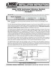
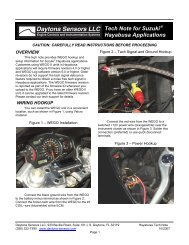
<strong>MSD</strong> <strong>RPM</strong> <strong>Activated</strong> <strong>Switch</strong><br />
PN 8950<br />
IMPORTANT: Read the instructions before attempting the installation.<br />
Parts Included:<br />
1 - <strong>RPM</strong> <strong>Switch</strong> 4 - Heat-Shrink Caps<br />
4 - Self Tapping Screws<br />
Note: <strong>RPM</strong> Modules must be purchased separately. See the chart on the last page for part numbers.<br />
The <strong>RPM</strong> <strong>Activated</strong> <strong>Switch</strong> can be connected to stock ignition systems or <strong>MSD</strong> Ignitions.<br />
When using a capacitive discharge ignition such as an <strong>MSD</strong>, do not connect the <strong>Switch</strong> to<br />
the coil negative terminal. Damage to the <strong>Switch</strong> may occur.<br />
The <strong>Switch</strong> is capable of carrying 1.5 amps. If the circuit you are activating requires more<br />
current, an <strong>MSD</strong> Relay, PN 8960 or 8961 must be used. The <strong>MSD</strong> <strong>RPM</strong> <strong>Activated</strong> <strong>Switch</strong> is<br />
equipped with a "smart driver". This circuit will protect the <strong>RPM</strong> <strong>Switch</strong> from damage by<br />
monitoring its temperature. If there is an inadvertant short or too much current is drawn<br />
through the <strong>Switch</strong>, the smart driver will sense the increased temperature and shut the<br />
<strong>Switch</strong> off. However, once the temperature drops to a safe point, the smart driver will turn the<br />
<strong>Switch</strong> back on. It will continuously cycle On and Off as the temperature dictates.<br />
If you experience a problem with your <strong>Switch</strong> not operating, turn the circuit off for a few minutes<br />
to cool, then try again. If the circuit activates then shuts off, there may be too much current<br />
flow. Check the device's Installation Instructions to find its recommended maximum current.<br />
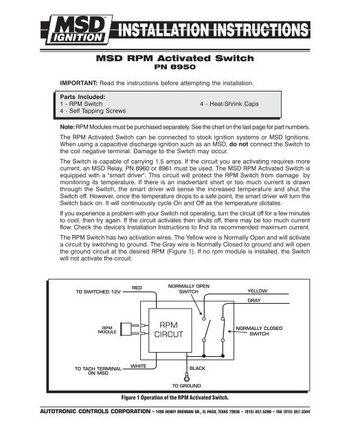
The <strong>RPM</strong> <strong>Switch</strong> has two activation wires. The Yellow wire is Normally Open and will activate<br />
a circuit by switching to ground. The Gray wire is Normally Closed to ground and will open<br />
the ground circuit at the desired <strong>RPM</strong> (Figure 1). If no rpm module is installed, the <strong>Switch</strong><br />
will not activate the circuit.<br />
Figure 1 Operation of the <strong>RPM</strong> <strong>Activated</strong> <strong>Switch</strong>.<br />
AUTOTRONIC CONTROLS CORPORATION • 1490 HENRY BRENNAN DR., EL PASO, TEXAS 79936 • (915) 857-5200 • FAX (915) 857-3344
2 INSTALLATION INSTRUCTIONS<br />
CYLINDER PROGRAMMING<br />
The <strong>Switch</strong> is programmed for 8-cylinder applications, however it can be used with 4 or 6-<br />
cylinder applications. To program the <strong>Switch</strong> for different applications, the cylinder select<br />
loops must be modified as shown in Figure 2. After cutting a wire loop, seal the wire end<br />
with the supplied heat-shrink caps. Use a heat gun or other heat source to shrink the cap<br />
for a good seal.<br />
CYLINDERS CUT LOOPS<br />
8 NONE<br />
6 RED<br />
4 RED & BLUE<br />
SEAL THE LOOP ENDS<br />
HEAT-SHRINK<br />
CAP CYLINDER LOOP<br />
RED<br />
BLUE<br />
Figure 2 Cylinder Select Loops.<br />
MOUNTING<br />
The <strong>Switch</strong> may be mounted under the hood as long as it is away from direct engine heat<br />
sources. Keep in mind that the rpm modules should be easy to access for changes. The<br />
<strong>Switch</strong> can be mounted with the double-sided tape or with the four self tapping screws<br />
supplied. Use the <strong>Switch</strong> as a template and mark the mounting hole locations. Remove the<br />
<strong>Switch</strong> and drill the holes using a 3/16" drill bit then install the screws.<br />
WIRING<br />
Red Connects to a switched 12 volt source.<br />
Black Connects to ground.<br />
White The rpm input wire. With an <strong>MSD</strong> Ignition, this connects to the Tach Output terminal.<br />
On inductive ignitions, it connects to the coil negative terminal.<br />
Yellow This is an activation wire and is Normally Open and will switch to ground. It connects<br />
to the ground side of the device you plan to activate.<br />
Gray This is an activation wire and is Normally Closed to ground. It will open the ground<br />
path of a circuit.<br />
Note: Inductive ignitions only.<br />
Figure 3 Wiring to an Inductive Ignition System.<br />
AUTOTRONIC CONTROLS CORPORATION • 1490 HENRY BRENNAN DR., EL PASO, TEXAS 79936 • (915) 857-5200 • FAX (915) 857-3344
INSTALLATION INSTRUCTIONS 3<br />
Note: Capacitive discharge ignitions only.<br />
Figure 4 Wiring to an <strong>MSD</strong> Ignition Control.<br />
Figure 5 Wiring with an <strong>MSD</strong> Relay.<br />
Figure 6 Wiring with an <strong>MSD</strong> Timing Control Retard.<br />
AUTOTRONIC CONTROLS CORPORATION • 1490 HENRY BRENNAN DR., EL PASO, TEXAS 79936 • (915) 857-5200 • FAX (915) 857-3344
<strong>RPM</strong> Module Kits are supplied with five modules in a range of 200 rpm increments. There are<br />
even number sets and odd number sets available. Example: PN 8746 includes 5,000,<br />
5,200, 5,400, 5,600, 5,800 modules.<br />
Kit Even Set Odd Set<br />
3,000 Kit PN 8743 87431<br />
4,000 Kit PN 8744 87441<br />
5,000 Kit PN 8745 87451<br />
6,000 Kit PN 8746 87461<br />
7,000 Kit PN 8747 87471<br />
8,000 Kit PN 8748 87481<br />
9,000 Kit PN 8749 87491<br />
10,000 Kit PN 8750 87501<br />
11,000 Kit PN 8751 87511<br />
12,000 Kit PN 8752 87521<br />
Module Selectors: These Selectors<br />
offer 12 different rpm limits at the<br />
turn of a knob. Note: Even rpm in<br />
200 rpm increments only.<br />
For rpm settings below 3000 rpm,<br />
<strong>MSD</strong> offers an adjustable Module,<br />
PN 8677<br />
<strong>RPM</strong> PART NUMBER<br />
3,000 - 5,200 PN 8670<br />
4,600 - 6,800 PN 8671<br />
6,000 - 8,200 PN 8672<br />
7,600 - 9,800 PN 8673<br />
9,000 - 11,200 PN 8674<br />
10,600 - 12,800 PN 8675<br />
Service<br />
In case of malfunction, this <strong>MSD</strong> component will be repaired free of charge according to the terms of<br />
the warranty. When returning <strong>MSD</strong> components for service, Proof of Purchase must be supplied for warranty<br />
verification. After the warranty period has expired, repair service is charged based on a minimum and<br />
maximum charge.<br />
Send the unit prepaid with proof of purchase to the attention of: Customer Service Department,<br />
Autotronic Controls Corporation, 12120 Esther Lama, Suite 114, El Paso, Texas 79936.<br />
When returning the unit for repair, leave all wires at the length in which you have them installed. Be<br />
sure to include a detailed account of any problems experienced, and what components and accessories<br />
are installed on the vehicle.<br />
The repaired unit will be returned as soon as possible after receipt, COD for any charges. (Ground<br />
shipping is covered by warranty). All units are returned regular UPS unless otherwise noted. For more<br />
information, call the <strong>MSD</strong> Customer Service Line (915) 855-7123. <strong>MSD</strong> technicians are available from 8:00<br />
a.m. to 5:00 p.m. Monday - Friday (mountain time).<br />
Limited Warranty<br />
Autotronic Controls Corporation warrants <strong>MSD</strong> Ignition products to be free from defects in material<br />
and workmanship under normal use and if properly installed for a period of one year from date of purchase.<br />
If found to be defective as mentioned above, it will be replaced or repaired if returned prepaid along with<br />
proof of date of purchase. This shall constitute the sole remedy of the purchaser and the sole liability of<br />
Autotronic Controls Corporation. To the extent permitted by law, the foregoing is exclusive and in lieu of<br />
all other warranties or representations whether expressed or implied, including any implied warranty of<br />
merchantability or fitness. In no event shall Autotronic Controls Corporation be liable for special or<br />
consequential damages.<br />
AUTOTRONIC CONTROLS CORPORATION • 1490 HENRY BRENNAN DR., EL PASO, TEXAS 79936 • (915) 857-5200 • FAX (915) 857-3344<br />
FRM23778 Revised 07/02 Printed In U.S.A.