rtd, resistance temperature detector - Scientific Devices Australia
rtd, resistance temperature detector - Scientific Devices Australia
rtd, resistance temperature detector - Scientific Devices Australia

Create successful ePaper yourself
Turn your PDF publications into a flip-book with our unique Google optimized e-Paper software.
AN105 Dataforth Corporation Page 1 of 3<br />
DID YOU KNOW <br />
Alessandro Volta was an Italian physicist born in 1745 who on March 20, 1800 announced his invention of the electric<br />
battery, which opened the way for electrical experiments, theories, and products. Among the many honors Volta received was<br />
an appointment by Napoleon to the position of “Count” in the French Empire. In his honor, the unit of electromotive force<br />
(volt) was named after him.<br />
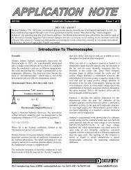
RTD, Resistance Temperature Detector<br />
Preamble<br />
Temperature measurements are perhaps the oldest known<br />
measurements. One of the most linear, stable, and<br />
reproducible <strong>temperature</strong> sensors is the Platinum RTD,<br />
Resistance Temperature Detector. The RTD’s <strong>resistance</strong><br />
vs <strong>temperature</strong> characteristics are stable, reproducible,<br />
and have a near linear positive <strong>temperature</strong> coefficient<br />
from –200 to 800 °C. These attributes establish RTDs as a<br />
de-facto industry standard. Temperature is determined by<br />
measuring <strong>resistance</strong> and then using the RTD’s “R vs T”<br />
characteristics to extrapolate <strong>temperature</strong>.<br />
Typical elements used for RTDs are Nickel (Ni), Copper<br />
(Cu), and Platinum (Pt). By far the most common are the<br />
100-ohm or 1000-ohm Platinum RTDs, sometimes<br />
referred to as PRTs, Platinum Resistance Thermometers.<br />
Historically, RTDs have been specified by their value at<br />
zero °C “R(0)”, and a positive <strong>temperature</strong> coefficient<br />
“alpha”, which is averaged from 0 to 100 °C. Over the<br />
years, both American and European RTD standards have<br />
been developed to ensure that RTDs are interchangeable<br />
from manufacturer to manufacturer without any<br />
significant loss in accuracy. Platinum RTDs have been<br />
defined by standards such as; DIN 43760 (BS1904), IEC<br />
751-1983, and JIS C1604. These standards specify RTD<br />
parameters, which include; R(0), alpha, tolerance<br />
classifications, and coefficients in the Callendar-Van<br />
Dusen mathematical model of <strong>resistance</strong> versus<br />
<strong>temperature</strong>.<br />
In the late 1990’s, the standard’s community published<br />
new standards in an effort to define a single definition for<br />
Platinum RTDs. Standards ASTM 3711 and IEC 60751<br />
represent the “new” Platinum RTD standards.<br />
Basics of Temperature Dependent Resistance<br />
The fundamental concept of <strong>temperature</strong> dependent<br />
<strong>resistance</strong> in metal conductors is illustrated in the<br />
following section. Complex quantum mathematical<br />
derivation details have been omitted.<br />
Current flow in any material is the flow of charged<br />
particles per unit time. In metals, these particles are<br />
electrons. Metals are excellent conductors because their<br />
molecular structure has an abundance of electrons<br />
“loosely” coupled to their molecular nuclei and are,<br />
therefore, readily available to move.<br />
Definitions:<br />
! The unit of charge is defined by the “Coulomb”<br />
! One ampere is defined to be a coulomb of charge<br />
flowing past a point in one second, coulomb/sec.<br />
! An electron (defined by “e”) has a negative charge of<br />
1.602E-19 coulombs. This means that there are<br />
6.24E18 electrons in one coulomb of charge and that<br />
1-ampere requires 6.24 billion billion electrons to<br />
travel past a point in one second.<br />
Imagine the total “chaos” inside a wire conducting only<br />
1-ampere, 6.24E18 electrons/sec. This huge jumbled mass<br />
of particles is “screaming” down a wire at an incredibly<br />
high average velocity. As they scramble along their way,<br />
they are “ interacting” with each other and “colliding”<br />
with the wire’s internal molecular structure. The Los<br />
Angeles freeway rush hour traffic appears at a dead<br />
standstill in comparison.<br />
An applied voltage (V applied ) forces “loose” electrons to<br />
move at an average velocity, which creates a current<br />
given by;<br />
i = dq/ dt = e× A× n× µ × V ) ÷ L, Amperes<br />
applied<br />
Where;<br />
! “e” is charge on an electron (1.6E-19 coulombs),<br />
! “A” is wire area,<br />
! “L” is wire length,<br />
! “n” is electron density, (number per unit<br />
volume), and<br />
! “µ“ is mobility, an extremely complex term that<br />
relates how electrons interact with each other and<br />
with the wire’s molecular structure.
AN105 Dataforth Corporation Page 2 of 3<br />
Rearranging this expression gives;<br />
Resistance (V ÷ i) = [(ρ×L)÷A] , Ohms.<br />
applied<br />
Where ρ = 1/( e× n×µ<br />
) and is the familiar parameter<br />
“resistivity”, which characterizes <strong>resistance</strong> of any given<br />
material. Note that since the electron charge “e” is a<br />
constant, <strong>resistance</strong> is completely dominated and<br />
controlled by the product of (n) electron density and (µ)<br />
electron mobility. For most metals over a rather large<br />
range of <strong>temperature</strong>, the (n x µ) product decreases with<br />
increasing <strong>temperature</strong>; this increases <strong>resistance</strong> and<br />
establishes a positive <strong>temperature</strong> coefficient. The number<br />
of electrons and their complex interactive behavior<br />
controls the <strong>resistance</strong> of materials.<br />
The complex interactive behavior of billions of electrons<br />
scrambling down a wire under the influence of<br />
<strong>temperature</strong> and a forcing voltage creates a resistivity that<br />
is seldom linear over all <strong>temperature</strong>. However, Copper,<br />
Nickel, and Platinum do have near linear <strong>temperature</strong><br />
coefficients over certain ranges of <strong>temperature</strong> and,<br />
therefore, are used in the manufacture of RTDs. Platinum<br />
is the most linear.<br />
RTD Model<br />
RTD standards, define Platinum <strong>resistance</strong> vs <strong>temperature</strong><br />
behavior by the Callendar-Van Dusen equation, a nonlinear<br />
mathematical model. These standards include; the<br />
RTD value at 0 °C, R(0), equation coefficients, and a<br />
<strong>temperature</strong> coefficient, alpha (α) defined from 0 to 100<br />
°C. Alpha (α) can sometimes be used to establish a simple<br />
linear model for <strong>resistance</strong> vs <strong>temperature</strong>. In addition,<br />
different tolerance ranges identified as “classes” are<br />
included within the associated standard’s information.<br />
The Platinum RTD Callendar-Van Dusen non-linear<br />
model is a forth order polynomial for negative<br />
<strong>temperature</strong>s and a quadric for positive <strong>temperature</strong>s.<br />
Cases 1, 2, 3 below show models for the RTD in the<br />
general form of RTD = R(0) + ∆R, where ∆R is the<br />
<strong>temperature</strong> dependent part of the RTD.<br />
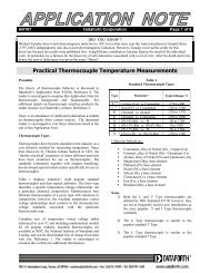
Measuring Temperature with RTDs<br />
Temperature measurements with RTDs first electronically<br />
measure the RTD <strong>resistance</strong> and then convert to<br />
<strong>temperature</strong> using the RTD’s <strong>resistance</strong> vs <strong>temperature</strong><br />
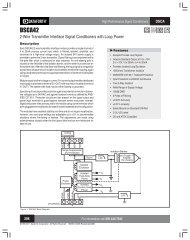
characteristics. There are numerous circuit topologies<br />
used to determine <strong>resistance</strong>. For example, Figure 1<br />
illustrates a classic bridge configuration used for 3-wire<br />
RTD measurements.<br />
RTD<br />
Rline3<br />
Rline2<br />
Rline1<br />
Field Side<br />
Rline1<br />
R3<br />
b<br />
a<br />
Module Side<br />
R2<br />
R1<br />
Figure 1<br />
The Classic 3-Wire RTD Bridge Topology<br />
Vref<br />
The voltage Vba in Figure 1 varies as RTD changes with<br />
<strong>temperature</strong>. For R1 = R2 = R3 = R(0), equal Rlines, and<br />
RTD defined as RTD = R(0) + ∆R then,<br />
Vref ⎡ ∆R ⎤<br />
Vba = ×<br />
2<br />
⎢<br />
2R(0)+∆R+2Rline<br />
⎥ .<br />
⎣<br />
⎦<br />
Typical bridge output voltages (as shown above) include<br />
line <strong>resistance</strong> and are non-linear.<br />
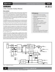
Modern semiconductor technology facilitates <strong>resistance</strong><br />
measurements with linear outputs and line <strong>resistance</strong>s<br />
eliminate. For example, Figure 2 illustrates a 4-wire RTD<br />
configuration with current excitation.<br />
Case (1) For T < 0; RTD = R(0) + ∆R<br />
2 3<br />
RTD = R (0) × [1 + A × T + B × T + C × ( T − 100) × T<br />
] .<br />
Case (2) For T > 0; RTD = R(0) + ∆R<br />
RTD = R (0) × [1 + A × T + B × T<br />
2<br />
] .<br />
RTD<br />
Rline4<br />
Rline3<br />
Rline2<br />
b<br />
a<br />
Iext<br />
Case (3) The linear model is; RTD = R(0) + ∆R<br />
RTD = R (0) × (1 + alpha × T<br />
) .<br />
Coefficients A, B, C, and alpha are defined by RTD<br />
standards and measured by RTD manufacturers as<br />
specified by these standards.<br />
Field Side<br />
Module Side<br />
Figure 2<br />
4-Wire RTD with Current Excitation
AN105 Dataforth Corporation Page 3 of 3<br />
In Figure 2, Vba = Iext x [ R(0) +∆R], which is a circuit<br />
linear output with line <strong>resistance</strong>s eliminated. Note, this<br />
scheme does not require equal line <strong>resistance</strong>s. Dataforth<br />
offers a 4-wire RTD module, the SCM5B35, which<br />
employs the scheme in Figure 2 including RTD vs T<br />
linearization and signal isolation.<br />
.<br />
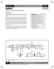
Figure 3 illustrates another Dataforth modern circuit<br />
technique for measuring <strong>resistance</strong> of a 3-wire RTD given<br />
as RTD = R(0) + ∆R.<br />
Rline3<br />
Rx<br />
I2<br />
RTD<br />
Rline2<br />
b<br />
Rline1<br />
a<br />
I1<br />
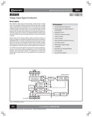
Figure 4<br />
Dataforth DSCA34 Linearized 2-or3-Wire RTD<br />
Field Side<br />
Module Side<br />
Figure 3<br />
Dataforth’s Resistance Measurement Method<br />
Given equal line <strong>resistance</strong>s (a reasonable assumption for<br />
field cable), this measurement technique eliminates their<br />
effect. Moreover, R(0), the <strong>temperature</strong> independent<br />
<strong>resistance</strong> part of the RTD is removed.<br />
If Rline3 = Rline2 = Rline1; Rx = R(0); I1 = I2= I; then<br />
Vba = ∆R x I, where ∆R is the <strong>temperature</strong> dependent<br />
<strong>resistance</strong> part of the RTD.<br />
This voltage “Vba” is electronically scaled and linearized<br />
to represent the actual <strong>temperature</strong>.<br />
Self Heating<br />
Self-heating errors can arise when the excitation circuit<br />
drives RTD sensors at power levels exceeding the<br />
manufacture’s specification. For example, if the excitation<br />
current (I) in Figure 2 is 250 micro-amps, which is<br />
Dataforth’s value for 100 Ohm RTDs, and <strong>temperature</strong> is<br />
–50 °C (~80 Ω), then RTD power dissipation would be ~5<br />
micro-watts. For industrial RTD sensors, current<br />
excitation less than 500 µA rarely cause self-heating<br />
errors. One should always check.<br />
Typical Dataforth Module<br />
Dataforth provides a complete line of signal conditioning<br />
modules that include isolation, input protection, and<br />
linearization for a variety of industrial applications. The<br />
reader is encouraged to visit Dataforth's website<br />
www.Dataforth.com for complete detail information on<br />
all Dataforth's product and additional application<br />
information.<br />
Additional Reference Links<br />
Listed below are informative web sites on RTDs<br />
1. NIST Thermometry Group,<br />
http://www.nist.gov/thermometry_group<br />
2. ASTM,<br />
www.astm.org<br />
3. IEC,<br />
http://www.iec.ch<br />
4. International Temperature Scale of 1990,<br />
http://www.its-90.com<br />
5. RTD Training and Information Resources,<br />
http://www.<strong>temperature</strong>s.com/<strong>rtd</strong>train.html<br />
6. Isothermal Technology,<br />
http://www.isotech.co.uk/weare.html<br />
http://www.isotech.co.uk/prtcalc-web.html<br />
7. 100Ohm RTD Platinum Table,<br />
http://www.prosensor.com/Anglais/Pages/Page02B-B-01-<br />
03.htm<br />
8. Honeywell,<br />
http://content.honeywell.com/building/components/Hycal<br />
_Html/temp.asp<br />
Figure 4 shows the topology layout of Dataforth’s DIN<br />
Rail mounted DSCA34 Linearized 2-or3-Wire RTD Input<br />
Signal Conditioning Module, which uses the above<br />
excitation method with isolation, surge protection, and<br />
linearization included.